Spanco PF Series Quick guide

ISO 9001:2015 Registered
Manual 103-0003
Assembly and Maintenance Instruction Manual
Effective October 2022
Promise to Perform Industries, Inc.
PF SERIES GANTRY CRANE

i Rigid Lifelines®Traveling Bridge Anchor Track™System | 1-800-869-2080 1-800-869-2080 | Rigid Lifelines®Traveling Bridge Anchor Track™System ii
i Spanco®PF-Series Gantry Crane • 1-800-869-2080 • Spanco.com
SPANCO GANTRY CRANE CONDITIONS OF USE AND WARNINGS STATEMENT
1. Read, understand, and follow the manual, assembly drawings, and warnings provided with your system before
beginning installation, use, or disassembly. Follow all instructions carefully.
2. This manual, and any other instructions, must be provided to the user(s) of this equipment. The user(s) must understand
the equipment’s proper use and limitations.
3. This crane is engineered to accommodate a standard hoist and a standard hoist weight. The standard hoist weight is
calculated at 15 percent of the crane’s rated capacity. Please inform Spanco if hoist weight exceeds 15 percent of the
crane’s rated capacity, or if the lifting speed exceeds 50 FPM.
4. ”Sidewinder” hoists or low headroom hoists with motors that are parallel to the beam can potentially impart large
torques (twisting moments) to the beam that can cause beam twisting and oscillations. Hoist inverter controls are heavily
recommended for all “sidewinder” hoists or low headroom hoists with motors that are parallel to the beam installed on
beam lengths over 12 feet.
NOTE: To eliminate any form of beam oscillation, use only an inverter controlled hoist of this type.
5. Power Drive options for motorized gantry travel are available for PF-Series Gantry Cranes only. Review Power Drive
installation instructions in the separate Power Drive instruction manual.
6. Motorized trolley travel is permissible for PF-Series and T-Series Gantry Cranes.
7. Each component and system must be employed and maintained in accordance with all OSHA and ANSI standards.
8. Use a hoist with the same or lower capacity rating as the gantry crane. Do not lift more than the rated crane capacity.
9. The rated capacity is displayed on a label on the Spanco system. Exceeding the capacities displayed on this label can
result in serious injury or death.
10. There should never be any type of loading past the end stops for any reason.
11. Never apply an off-plumb load to the system.
12. Always check for overhead hazards, such as power lines, trees, equipment, overhead structures, or walls, before using or
moving a portable system.
13. Never use this system as fall protection or for lifting, hoisting, or carrying personnel.
14. When moving the gantry under load, keep the load in the center of the beam and as close to the ground as possible.
15. Before moving the gantry under load, remove any obstacles and ensure that the load is not attached to the floor.
16. Spanco Gantry Cranes are designed to be moved manually. Do not push or pull the gantry with a lift truck or other
vehicle.
17. When moving a gantry crane under load, push the gantry; do not push or pull the suspended load.
18. Never exceed two people pushing an Aluminum gantry crane.
19. Do not disassemble the gantry or adjust the height, span, or caster frame spread (if applicable) when the gantry is under
load.
20. Do not stand under the gantry when it is being adjusted in height, span, or caster frame spread.
21. Do not stand or walk under a suspended load.

i Rigid Lifelines®Traveling Bridge Anchor Track™System | 1-800-869-2080 1-800-869-2080 | Rigid Lifelines®Traveling Bridge Anchor Track™System ii
Spanco.com • 1-800-869-2080 • Spanco®PF-Series Gantry Crane ii
SPANCO GANTRY CRANE CONDITIONS OF USE AND WARNINGS STATEMENT
22. Caster frame spread must be a minimum of 40 percent of the overall height (T-Series only).
23. Adjustments and repairs must be made in an area that does not interfere with operation.
24. Do not load the gantry on an incline.
25. Do not allow the load to swing or roll against the gantry support members.
26. Do not slam the hoist trolley against the end stops or gantry supports at any time.
27. The system must be tied down if exposed to winds exceeding 30 miles per hour. Spanco considers it an unsafe practice
to operate cranes in winds over 15 miles per hour. Although the drive may work in speeds exceeding 15 miles per
hour, Spanco does not recommend using any crane in winds over 15 miles per hour for safety reasons. If quoted
for a pre-defined wind speed, the drive components have been designed for an approximate wind speed. It is the
responsibility of others to generate a risk assessment of wind conditions and part stability, and to generate a lifting plan
that accounts for the sail effect of the part being lifted and the length of the cable the part is suspended on. Notify
Spanco if the system will be subjected to constant buffeting winds.
28. Although Spanco may provide components that are intended for service in a specific environment, it is the customer’s
responsibility to confirm that the provided Spanco system and components will work in and are acceptable for their
specific application and environment.
29. Before each use, inspect the system for bent, broken, cracked, or missing components.
30. Thoroughly inspect the system annually per OSHA law.
31. Per OSHA law, load testing must be performed before the system can be placed into service.
32. Engineering of any attachment points must be done by others.
33. Component appearances and dimensions shown are approximate and subject to change without notice. All literature
dimensions are developed using standard components for the spans and capacities. Substitution of optional trolleys or
other components will affect certain dimensions.
34. Never deviate from the above unless you have written permission and authorization from Spanco.

iii Rigid Lifelines®Traveling Bridge Anchor Track™System | 1-800-869-2080 1-800-869-2080 | Rigid Lifelines®Traveling Bridge Anchor Track™System 1
iii Spanco®PF-Series Gantry Crane • 1-800-869-2080 • Spanco.com
Follow the Inspection Checklists in this manual: review the checklist on page 17 before each use and review the checklist
on page 18 annually.
SYSTEM APPLICATIONS
The Spanco system is used for material handling applications. This material handling system is labeled with a maximum rated
capacity and is designated for Class C service as defined by the CMAA; follow all limitations as noted on system labels.
STANDARDS AND COMPLIANCE
Please refer to local, state, and federal (OSHA) requirements governing occupational safety for additional information
regarding material handling. The Spanco system meets or exceeds the requirements set forth in OSHA 1910.179, ANSI
B30.11, and CMAA 70.
REQUIRED TRAINING
This system is intended to be used by people who are trained in its correct application and use. It is the responsibility of the
users and the users’ management to ensure that they are familiar with OSHA law and these instructions, and that they are
trained in the correct use and care of this equipment. Authorized users must also be aware of the operating characteristics,
application limits, and the consequences of improper use, which can result in serious injury or death. All users must read and
understand CMAA 79 Crane Operator’s Manual.
Every material handling application must be OSHA compliant. Safety and training measures may include, but are not limited
to:
• Operator certification training
• Operator evaluation program
• Hand signal protocols if required
• Lock-out/Tag-out training
The above list is not a comprehensive list. Specific applications may need to include additional protocols. For more information
on how to set up a proper lift plan within your facility, follow CMAA 79
Crane Operator’s Manual.

iii Rigid Lifelines®Traveling Bridge Anchor Track™System | 1-800-869-2080 1-800-869-2080 | Rigid Lifelines®Traveling Bridge Anchor Track™System 1
Spanco.com • 1-800-869-2080 • Spanco®PF-Series Gantry Crane 1
TABLE OF CONTENTS
CONDITIONS OF USE AND WARNINGS STATEMENT .................................................................................................i-iii
SYSTEM APPLICATIONS ................................................................................................................................................... iii
STANDARDS AND COMPLIANCE .................................................................................................................................... iii
REQUIRED TRAINING........................................................................................................................................................ iii
ASSEMBLY INSTRUCTIONS ................................................................................................................................................2
1. Equipment Needed for Assembly ................................................................................................................................2
2. Inventory ....................................................................................................................................................................2
3. Attaching the Caster Brakes to the Caster Assemblies .................................................................................................3
4. Attaching the Swivel Locks to the Caster Assemblies...................................................................................................4
5. Attaching the Caster Assemblies to the Leg Assemblies........................................................................................... 4-5
6. Attaching the Leg Connection Plates...........................................................................................................................5
7. Attaching the Brace Tubes....................................................................................................................................... 6-7
8. Attaching the Leg Assemblies to the Beam.............................................................................................................. 7-8
FINAL ASSEMBLY ................................................................................................................................................................8
OPTIONAL ACCESSORIES...................................................................................................................................................8
1. V-Groove Track ....................................................................................................................................................... 8-9
2. Power Drive ............................................................................................................................................................. 10
3. Clamp-On Tagline................................................................................................................................................10-11
MAINTENANCE................................................................................................................................................................. 12
LOAD TEST......................................................................................................................................................................... 12
DESIGN AND SERVICE FACTORS ................................................................................................................................... 12
DISASSEMBLY................................................................................................................................................................... 13
1. Removing the Leg Assemblies .................................................................................................................................. 13
2. Removing the Brace Tubes ....................................................................................................................................... 14
3. Removing the Leg Connection Plates ....................................................................................................................... 15
NOTES................................................................................................................................................................................. 15
LABELING .......................................................................................................................................................................... 16
PF-SERIES GANTRY CRANE INSPECTION CHECKLISTS ............................................................................................... 17
Before Each Use Inspection Checklist............................................................................................................................ 17
Annual Inspection Checklist.......................................................................................................................................... 18
PRODUCT WARRANTY COVERAGE AND SERVICE POLICY........................................................................................ 19
ABOUT SPANCO ............................................................................................................................................. BACK COVER

Promise to Perform Industries, Inc.
PF-SERIES GANTRY CRANE MANUAL
2 Spanco®PF-Series Gantry Crane • 1-800-869-2080 • Spanco.com
ASSEMBLY INSTRUCTIONS
1. Equipment Needed for Assembly
a ) This manual
b ) Applicable safety equipment for workers’ use during assembly, such as hard hats, steel toe shoes, etc.
c ) Multiple telescoping lift trucks, cranes, or other lifting equipment with at least the minimum height and lifting
capacity required as determined by the size and weight of the gantry crane.
d ) Man lift/cherry picker (minimum height determined by installed system height)
e ) Measuring tape
f ) Torque wrench
g ) Lifting straps
h ) Several six-inch by six-inch (or larger) wood blocks
i ) Long carpenter’s level or laser level
j ) Wrench/socket sets up to 1-1/8 inch
k ) A spacious, level area for assembly (e.g., parking lot)
l ) PF-SERIES-ASSEMBLY SHEET 1 OF 2, hereafter referred to as PF-Series Gantry Crane Assembly Drawing, included as
a separate document.
m ) PF-SERIES-ASSEMBLY SHEET 2 OF 2, hereafter referred to as PF-Series Gantry Crane Label Placement Drawing,
included as a separate document.
2. Inventory
a ) Open all bundles and confirm that all components are accounted for: see Building Materials Description located in
the top right corner of the PF-Series Gantry Crane Assembly Drawing. Note that the quantity of components in an
assembly are multiplied by the number of the assemblies.
b ) Check for damage to components that may have occurred during shipping.
c ) Your PF-Series Gantry Crane consists of the following components:
1 ) One Beam
2 ) Two left leg assemblies
3 ) Two right leg assemblies
4 ) Two middle brace tubes
5 ) Two lower brace tubes
6 ) Four Casters
7 ) Four connecting plates

Spanco.com • 1-800-869-2080 • Spanco®PF-Series Gantry Crane 3
Promise to Perform Industries, Inc.
3. Attaching the Caster Brakes to the Caster Assemblies
Refer to PF-Series Gantry Crane Assembly Drawing for Steps A Through J
WARNING: Crane parts are heavy. Use proper rigging and support on all parts during assembly and disassembly
processes. Do not stand under the crane during assembly or disassembly.
a ) Select an area under an overhead hoist, or where a lift truck or multiple lift trucks can be used to raise the beam.
Be sure there is no machinery or clutter nearby that will obstruct free movement. All personnel should be wearing
applicable safety gear, such as hard hats, steel toe shoes, and safety glasses.
b ) Depending on the system, some polyurethane casters ship with the brakes already attached. If you ordered
polyurethane casters, and the brakes were shipped loose, follow steps c) through j) to attach the caster brakes.
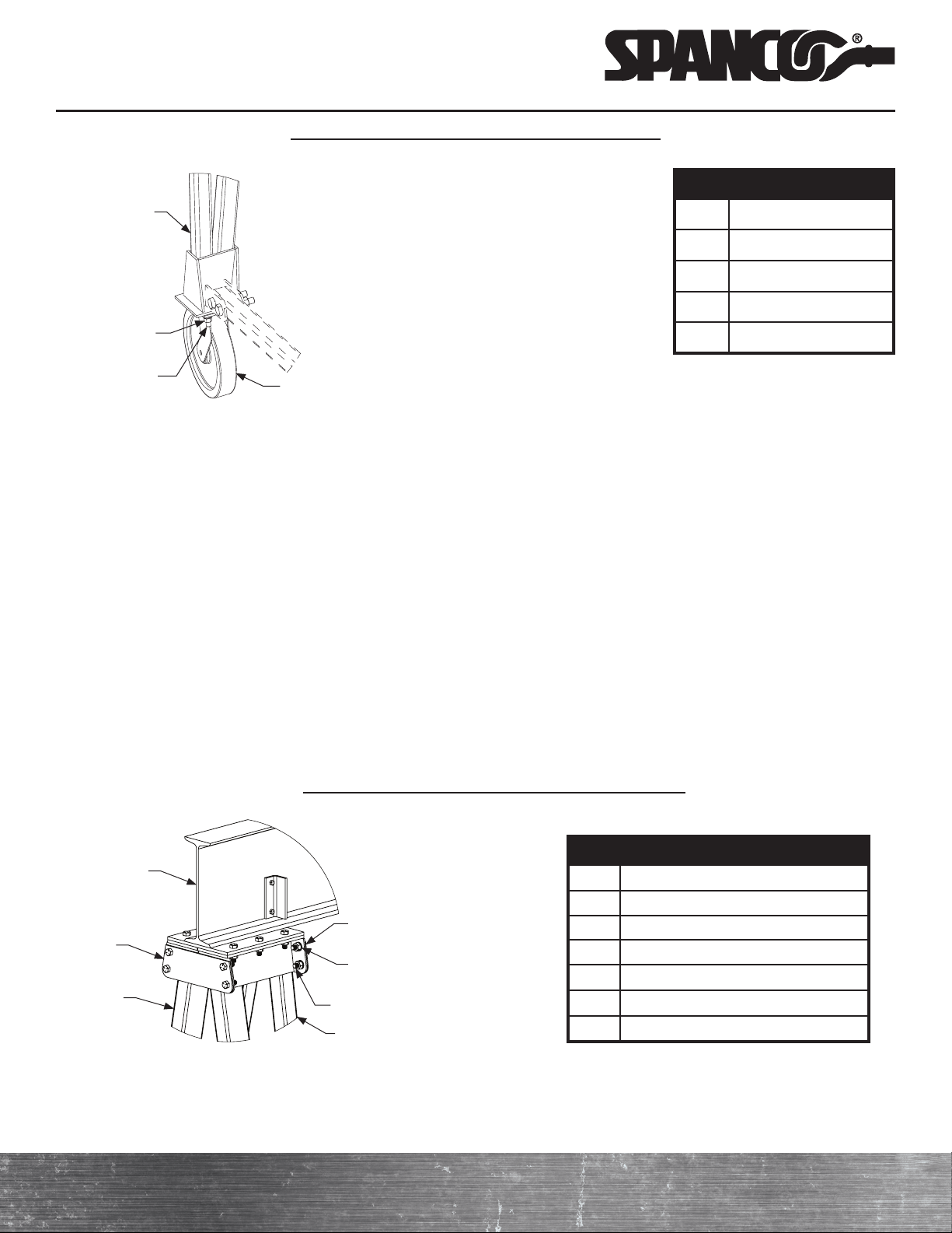
Refer to the caster brake assembly drawing below throughout the assembly process.
Detail “E”
c ) Using a 3/4-inch wrench and 3/4-inch socket and ratchet, unbolt the caster stud and remove the nut, bolt, washer,
and caster.
NOTE: If the spacers fall out of the caster, reinsert them into the caster holes.
d ) With the top of the brake shoe facing towards the caster assembly, insert the guide pin on the brake shoe into the
brake slot on the caster assembly.
e ) Using a screwdriver, slightly bend the brake shoe tab so that the brake shoe guide pin and brake shoe tab fit
properly.
f ) With the brake pedal tabs pointed away from the caster assembly, line up the hole on the brake pedal with the hole
on the brake shoe. "On" and "Off" on the brake pedal tabs should be visible when the caster is mounted to the
system.
g ) Line up the caster holes with the brake shoe hole and brake pedal hole.
h ) With the washer on the bolt-side of the caster assembly, reinsert the longer axle bolt through the brake pedal,
brake shoe, and caster. Reapply the axle nut at this time.
i ) Using a 3/4-inch wrench and 3/4-inch socket and ratchet, securely tighten the caster nut.
j ) Repeat steps b) through i) to install the remaining caster brakes.
Brake shoe (leg)
Brake pedal
Cup spring washer
Shouldered axle bolt
Caster
Shoe guide pin
Brake slot
Hex nut

Promise to Perform Industries, Inc.
PF-SERIES GANTRY CRANE MANUAL
4 Spanco®PF-Series Gantry Crane • 1-800-869-2080 • Spanco.com
4. Attaching the Swivel Locks to the Caster Assemblies
Refer to PF-Series Gantry Crane Assembly Drawing for Steps A Through G
a ) If applicable, the swivel lock ships zip-tied to the caster assembly for polyurethane casters. For polyurethane casters,
you should have removed the swivel lock while installing the caster brakes.
b ) Insert the pin on the swivel lock into the groove beneath the caster plate on the caster assembly.
c ) Open the pin on the swivel lock by pulling and spinning the ring to fit into the groove at the end of the swivel lock.
d ) Using two 3/4-inch bolts, washers, and nuts, bolt the swivel lock to the caster plate.
e ) Using a 3/4-inch wrench and 3/4-inch socket and ratchet, tighten the swivel lock bolts to 257 foot-pounds.
f ) Repeat steps b) through e) to install the remaining swivel locks.
g ) Test the caster brakes and swivel locks to ensure they function properly.
5. Attaching the Caster Assemblies to the Leg Assemblies
Refer to PF-Series Gantry Crane Assembly Drawing for Steps A Through I
NOTE: To simplify assembly, arrange the parts on the floor according to the diagram below.
ITEM DESCRIPTION
1 Beam
2 Right Leg Assembly
3 Left Leg Assembly
4 Upper Brace Tube
5 Lower Brace Tube
6 Leg Connection Plate
8 Caster
16
32
45
8
32
a ) Lay each right leg assembly (2 in the Building Materials Description) and left leg assembly (3 in the Building
Materials Description) on the ground.
b ) Per Detail “A,” position the caster assembly under the leg’s base plate (where the inner and outer segments of
each leg assembly join together). Insert the welded, threaded studs on the bottom of the leg assembly into the
holes in the caster assembly’s top plate.
c ) Per Detail “A,” place a flat washer (9), lock washer (10), and hex nut (11) onto each stud so that the lock washer
(10) is between the flat washer (9) and the hex nut (11). Torque all 1/2-inch wheel stud nuts (11) to 23 foot-pounds.
d ) Repeat steps b) and c) to attach the remaining caster assemblies.
e ) For casters with a bolted connection, align the holes in the leg’s base plate with the holes in the caster assembly’s
top plate.
f ) Per Detail “A,” insert a bolt (22) through each of the aligned holes in the leg and the caster assembly so that the
bolts (22) extend from the leg through the caster assembly’s top plate.
g ) Per Detail “A,” place a flat washer (9), lock washer (10), and hex nut (11) on each bolt (22) so that the lock washer (10)
is between the flat washer (9) and hex nut (11). Torque all nuts (11) to the correct value specified by the torque chart.
NOTE: Leg sets are match marked.
Spanco.com • 1-800-869-2080 • Spanco®PF-Series Gantry Crane 5
Promise to Perform Industries, Inc.
h ) Repeat steps e) through g) to attach the remaining caster assemblies to the leg assemblies.
i ) After the wheel brakes, swivel locks, and caster assemblies have been attached to the system, test the wheel brakes
and swivel locks to ensure they function properly.
6. Attaching the Leg Connection Plates
Refer to PF-Series Gantry Crane Assembly Drawing for Steps A Through E
a) After the caster assemblies have been attached, lay one right leg assembly (2 in Building Materials Description) and
one left leg assembly (3 in Building Materials Description) on the ground so that the long side of the upper brace tube
lugs point up. The outer legs should be on the ground and the inner legs should be off the ground.
b ) Per Detail “D,” position the wide ends of both leg assemblies (their tops) so they are next to one another. Lift the
tops of both leg assemblies together and place a six-inch by six-inch (or larger) wood block under their outer legs to
make the upcoming bolt insertion easier.
c ) Per Detail “D,” align one leg connection plate (6) with the four holes on the outer-facing plates at the top of the
leg assemblies. Attach the leg connection plate (6) with four sets of bolts (19), lock washers (20), and hex nuts (21).
Securely tighten all nuts. Attach a second leg connection plate (6) the same way to the inside-facing plates at the
top of the leg assemblies.
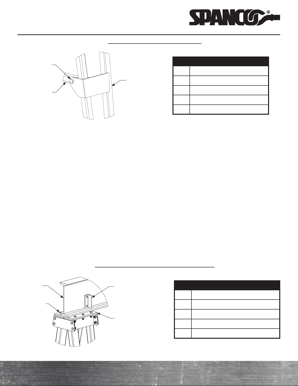
Detail "D" (Beam and Leg Connection Plates to Legs)
NOTE: 9, 10, and 11 attach to a stud welded
to the bottom of the leg assembly. On some
models, the welded studs are replaced with
hex bolts (22).
ITEM DESCRIPTION
2 Right Leg Assembly
9 Flat Washer
10 Lock Washer
11 Hex Nut
22 Hex Bolt
NOTE: Torque all 1/2-inch wheel stud nuts
(11) to 23 foot-pounds only.
9 10 11
2
ITEM DESCRIPTION
1 Beam
2 Right Leg Assembly
3 Left Leg Assembly
6 Leg Connection Plate
19 Hex Bolt (Short)
20 Lock Washer
21 Hex Nut
2
6
319
20 21
1
8
Welded Stud
Detail “A” (Casters and Lower Brace Tubes to Legs)
d ) Repeat steps athrough c for the second set of right (2) and left (3) leg assemblies.
e ) All four leg connection plates (6) for the tops of the leg assemblies should now be attached, giving you two sets of
partially assembled legs.
NOTE: 15-ton capacity models may require a
crows foot to torque bolts properly.
6

Promise to Perform Industries, Inc.
PF-SERIES GANTRY CRANE MANUAL
6 Spanco®PF-Series Gantry Crane • 1-800-869-2080 • Spanco.com
e ) Per Detail “C,” bolt the brace tube (4) to the inner upper brace tube lug using a bolt (15), lock washer (16), and
hex nut (17) for both left leg assemblies (3). Securely tighten the nuts.
ITEM DESCRIPTION
2 Right Leg Assembly
3 Left Leg Assembly
4 Upper Brace Tube
5 Lower Brace Tube
8 Caster
12 Hex Bolt (Long)
13 Lock Washer
14 Hex Nut
12 13 14
5
8
ITEM DESCRIPTION
2 Right Leg Assembly
4 Upper Brace Tube
15 Hex Bolt (Long)
16 Lock Washer
17 Hex Nut
15 16 17
2
4
7. Attaching the Brace Tubes
Refer to PF-Series Gantry Crane Assembly Drawing for Steps A Through E
a ) To make inserting bolts easier during the following steps, place six-inch by six-inch (or larger) wood blocks under
each outer leg between the tops of the legs, the lug for the upper brace tube (4 in Building Materials Description),
and the casters (8).
b ) Per Detail “A,” attach the lower brace tube (5) to the lower brace tube lug at the base of each leg assembly (2
and 3) using two bolts (12), lock washers (13), and hex nuts (14) for each end of the lower brace tube. Securely
tighten the nuts.
Detail "A" (Casters and Lower Brace Tubes to Legs)
c ) Place the upper brace tube (4) between the upper brace tube lugs located at the middle of the right and left leg
assemblies (2 and 3).
d ) Per Detail “B,” bolt the brace tube (4) to the upper brace tube lug using a bolt (15), lock washer (16), and hex nut
(17) for both right leg assemblies (2). Securely tighten the nuts.
Detail "B" (Upper Brace Tube to Right Leg)
NOTE: (Detail “A,” Detail “B,” and Detail
“C”) Torque all 5/8-inch leg bracing bolts
(12 and 15) to 48 foot-pounds. Torque all
3/4-inch leg bracing bolts (12 and 15) to 77
foot-pounds.
Spanco.com • 1-800-869-2080 • Spanco®PF-Series Gantry Crane 7
Promise to Perform Industries, Inc.
Detail "C" (Upper Brace Tube to Left Leg)
8. Attaching the Leg Assemblies to the Beam
Refer to PF-Series Gantry Crane Assembly Drawing for Steps A Through K
a ) Evenly balance the beam (1 in Building Materials Description) on top of two six-inch by six-inch (or larger) blocks so
that the labels are right-side-up and legible.
b ) Feed a lifting strap or lifting straps under the beam (1) so the beam weight will be evenly distributed during lifting.
c ) Attach the other end of the lifting strap(s) to your lifting equipment (fork truck[s] or overhead crane[s]) to hoist the
beam (1) into the air.
NOTE: Follow all applicable rigging and lifting requirements as determined by the size and weight of the gantry
crane. Ensure the beam is properly balanced and safely secured before lifting to full height.
d ) Raise the beam into the air and install the trolley and hoist according to the manufacturer’s recommendations onto
the lower flange of the beam and secure it in the middle of the span.
NOTE: The register plates are welded to the bottom flange of the beam on both sides, so the trolley must be
separated to be installed on the beam.
e ) Raise the beam high enough to allow both leg assemblies to fit under the connection points on the beam.
f ) Position the assembled legs so the upper brace tube (4) is on the outside of the leg assembly when the legs are
lifted into place.
g ) Use a man lift to allow a worker to reach the height of the beam.
Detail “D” (Beam and Leg Connection Plates to Legs)
ITEM DESCRIPTION
3 Left Leg Assembly
4 Upper Brace Tube
15 Hex Bolt (Long)
16 Lock Washer
17 Hex Nut
4
15 16 17
3
ITEM DESCRIPTION
1 Beam
7 End Stop Angle
18 Hex Bolt (Medium)
20 Lock Washer
21 Hex Nut
18 20 21
17
Register Plate

Promise to Perform Industries, Inc.
PF-SERIES GANTRY CRANE MANUAL
8 Spanco®PF-Series Gantry Crane • 1-800-869-2080 • Spanco.com
BOLT DIAMETER HEX NUT TORQUE MINIMUM HEX LOCKNUT TORQUE
1/2 Inch 78 Foot-Pounds 51 Foot-Pounds
5/8 Inch 154 Foot-Pounds 93 Foot-Pounds
3/4 Inch 257 Foot-Pounds 151 Foot-Pounds
7/8 Inch 341 Foot-Pounds 224 Foot-Pounds
1 Inch 514 Foot-Pounds 325 Foot-Pounds
OPTIONAL ACCESSORIES
1. V-Groove Tack Installation
a ) The exact span of the crane may vary from the design span. Install the full length of the track on one side, making
sure that the track is straight and level. Fasten V-groove track to the floor using 3/8-inch lag bolts and suitable
anchors. (For track supplied by Spanco, use a bolt in each hole. Otherwise, space bolts approximately three feet
apart on each side of the track in a staggered arrangement.) Use shims or grouting as required to keep the track
level and alignment pins at joints to keep the track true. End stops are required at each end of both tracks.
b ) Lay one or two sections of the opposite side of the track at the design span, assemble the crane on the tracks
following the assembly instructions, and operate the crane back and forth a few times, being careful not to run the
crane off the tracks. The loose sections of track will float and set the track to the exact crane span.
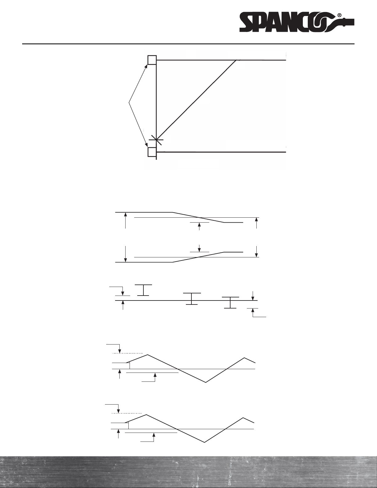
c ) After the operating span is determined, attach all the other sections of track to the floor making sure the track is
straight, level, parallel, and at the same elevation as the first track. The end stops should be set square with a 3-4-5
right triangle. The sides and the hypotenuse can be multiplied by any convenient number, such as three, used in the
example.
d ) Set one end stop at point A and measure along the runway track nine feet from point A to point B. With point B as
a center and 15 feet as a radius, draw a circular arc on the floor. With point A as a center and 12 feet as a radius,
draw a circular arc on the floor intersecting the other arc at point C. A line running through points A and C is
perpendicular, or square, with the runway track.
e ) Extend this line to the other runway track to locate the end stop on that runway. Repeat the process at the other
end of the runway, or measure along each runway the same distance from these end stops for locating the stops at
the other end of the runways.
NOTE: For v-groove track, the anchors can be epoxy anchors, or “wedge” anchors, after the floor is completed.
NOTE: This torque value chart is based on grade 5 fasteners. Reduce torque value for lower grade fasteners as needed.
See torque notes with individual steps for torque values that differ from the values in the above torque chart.
h ) Per Detail “D,” use an additional lift truck or crane to lift the top portion of one leg assembly underneath the
beam. Use drift pins to align the six holes in the beam (1) register plate with the six holes in the top plate of the leg
assembly.
i) Attach the plates together using bolts (18), lock washers (20), and hex nuts (21). Securely tighten the nuts.
j ) Repeat steps gthrough jto assemble the other end of the beam (1 in Building Materials Description) and the
remaining leg assembly.
k ) Use the supplied shims to plum the legs and align the wheels as necessary.
9. Final Assembly
a ) Confirm that all bolts are fully seated, all washers are in place, and all nuts are securely tightened.
b ) Use the man-lift to allow a worker to access all of the system nuts. Torque all of the nuts on the system to the
specifications shown below before removing support rigging.
Spanco.com • 1-800-869-2080 • Spanco®PF-Series Gantry Crane 9
Promise to Perform Industries, Inc.
RUNWAY ALIGNMENT TOLERANCE FOR V-GROOVE TRACK
Span
(2 Runway)
Straightness
Elevation
A=3/16” in any
support span
C=1/4” in any
support span
D=1/4” in any
support span
Rail to Rail
Elevation
E=1/4” between
adjacent rails
Nom. Span
(L)
Max. Span
(L+A)
Min. Span
(L-A)
Nom. Tread Line
+E
-E
+C
-C
+D
-D
End Stops
A 9’ Runway Track
B
C
12’ 15’
Runway Track
Promise to Perform Industries, Inc.
PF-SERIES GANTRY CRANE MANUAL
10 Spanco®PF-Series Gantry Crane • 1-800-869-2080 • Spanco.com
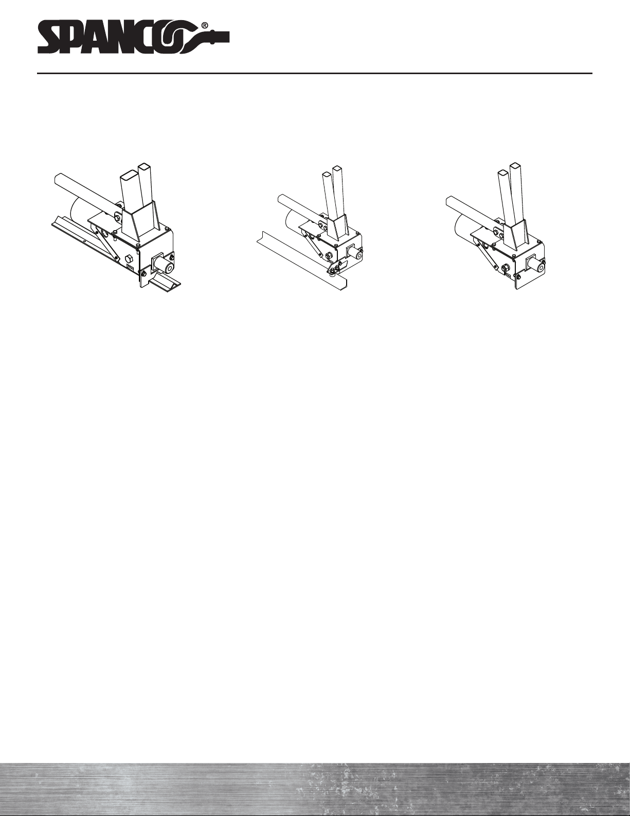
2. Power Drive
Spaco Power Drive Kits are an economical way to drive high-volume, high-capacity gantry travel, so one worker can
guide loads up to 15 tons using a control pendant. The Kits are easy to install and can be specified on new gantries or
retrofitted onto your existing Spanco PF-Series Gantry Cranes.
Guide Angle Drive (Guide Angle or
Guide Channel supplied by others)
Trackless Path (manual guidance via
motor control)
V-Groove Tracks
a ) Install beam electrification and connect all electrical components if required. Ensure all equipment travels in the
direction indicated on the control station.
b ) A complete electrical/mechanical manual is supplied separately for the power dive. Refer to the electrical/mechanical
manual to correct any errors in operation. All work on electrical components must be completed by a certified
industrial electrician.
c ) Before operating the power drive, check the oil level in all gear boxes. Ensure all wheels and roller chains are
properly lubricated.
d ) Operate the gantry crane along the full length of the track or operating area several times to ensure it tracks
properly and clears all obstructions. If any problems occur while tracking, ensure the legs are plumb. Adjust shims to
plumb the legs as needed.
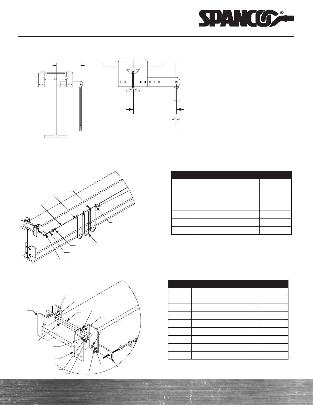
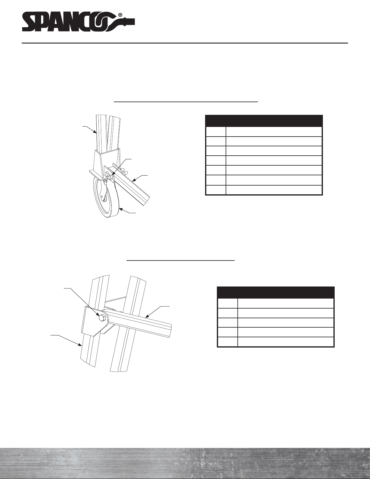
3. Tagline Assembly
Spanco clamp-on tagline assemblies are designed for universal installation. Clamp-on tagline assemblies include universal
weldments, applicable hardware, tagline cable, cable clamps, eyebolts, and pulleys with cable ties. One pulley and cable
tie is provided for every five feet of tagline length. Power conductor is supplied by others.
Installation
a ) Trim excess rod length to fit socket (if desired).
NOTE: Align each rod so only one end requires trimming.
b ) Torque the inner lower rod nuts (9) to 33 foot-pounds. Adjust the inner upper rod nuts (9) to keep the weldments
plumb.
c ) Holding the inner lower rod nuts in place with a wrench, torque the outer lower rod nuts (9) to 33 foot-pounds.
d ) Holding the inner upper rod nuts in place with a wrench, torque the outer upper rod nuts (9) to 33 foot-pounds.
e ) Align the correct holes in the arm plate (11) with the holes in the tagline weldment (7) and insert two hex head bolts
(13) through the holes. Align the arm plate to keep the tagline approximately 10 inches from the face of the beam.
f ) Place a lock washer (12) and nut (14) on each bolt (13). Torque the nuts (14) to 10 foot-pounds.
Spanco.com • 1-800-869-2080 • Spanco®PF-Series Gantry Crane 11
Promise to Perform Industries, Inc.
BILL OF MATERIALS
ITEM DESCRIPTION QUANTITY
1 Cable Clamp 2
2 Tagline Cable 1
3 Eye Bolt 2
4 1/4-Inch Hex Nut 4
5 Pulley X
6 Cable Tie X
BILL OF MATERIALS
ITEM DESCRIPTION QUANTITY
7 Tagline Weldment 2
8 3/8-Inch Threaded Rod 2
9 3/8-Inch Hex Nut 8
10 3/8-Inch Flat Washer 6
11 Arm Plate 1
12 1/4-Inch Lock Washer 2
13 1/4-Inch Hex Head Bolt 2
14 1/4-Inch Hex Nut 2
Note: Only one end of the beam is shown. Total
quantities are doubled.
approx. 10
inches
approx. 10
inches
NOTE: Position the Arm Plate so that
the tagline is approximately 10 inches
from the face of the beam.
Figure 1
Figure 3
1
2
3
4
5
6
Power Conductor
Figure 2
From Supply To Equipment
7
7
8
8
9
10
9
10
10
911
12
13
14
9

Promise to Perform Industries, Inc.
PF-SERIES GANTRY CRANE MANUAL
12 Spanco®PF-Series Gantry Crane • 1-800-869-2080 • Spanco.com
MAINTENANCE
1. A system inspection should be performed 30 days after installation. All nuts, bolts, and screws should be checked for
tightness. All end stops, cotter pins, and hoist trolleys should be checked for abnormal wear or breakage.
2. A complete inspection of all fasteners and connections should be performed annually or every two thousand (2,000)
hours. Heavy conditions of use may require more frequent inspections.
3. Operators should visually inspect the system before each use to note any unusual or abnormal system operations.
4. If the system fails ANY inspection point on any of the inspection checklists, immediately remove the system
from service and call Spanco®at 800-869-2080 for instructions.
5. Download and print additional blank inspection checklists from the literature tab at Spanco.com.
LOAD TEST
After the PF-Series Gantry Crane has been installed, OSHA requires a load test before operating and after any modifications.
This equipment is designed and manufactured to the rated capacity marked on the equipment with due allowances for safety
factors. Prior to initial use of the Gantry Crane, a person appointed by the owner, under the direction of a qualified technical
person, must perform a load test at 125 percent of the rated capacity using certified test weights. See CMAA 78 for periodic
load testing requirements. Under no conditions shall the rated capacity be exceeded during regular use or during annual or
semi-annual load tests.
DESIGN FACTOR
Nameplate capacities represent the rated load on the hoist hook. The load rating of a hoist shall not exceed the nameplate
capacity. Spanco’s design includes an allowance of 15 percent of nameplate capacity for trolley and hoist deadweight and
25 percent of the nameplate capacity for impact. This design provides a margin to allow for variations in material properties,
operating conditions, and design assumptions. No crane should ever be loaded beyond its rated capacity.
SERVICE FACTOR
All Spanco gantry cranes are designed for moderate usage (Class C Moderate Service) as defined by CMAA 70:
• System or equipment is used where lifted loads average 50 percent of the rated capacity with five to 10 lifts per hour,
averaging 15 feet, not over 50 percent of the lifts at rated capacity.
Applications involving vacuums, magnets, or other high-impact lifters are considered severe usage and require special design
considerations. Contact Spanco for special design pricing.
Consult Spanco for usage other than Class C and all instances of high cycle rates or high-impact applications such as high-
speed air or electric hoists, vacuum lifters, or magnets.

Spanco.com • 1-800-869-2080 • Spanco®PF-Series Gantry Crane 13
Promise to Perform Industries, Inc.
ITEM DESCRIPTION
1 Beam
7 End Stop Angle
18 Hex Bolt (Medium)
20 Lock Washer
21 Hex Nut
18 20 21
17
Register Plate
DISASSEMBLY
1. Removing the Leg Assemblies
Refer to PF-Series Gantry Crane Assembly Drawing for Steps A Through J
WARNING: Crane parts are heavy. Use proper rigging and safely support all parts during the disassembly process.
a ) Read and understand each step before beginning the disassembly process.
b ) Move the assembled PF-Series Gantry Crane to an area under an overhead hoist, or where multiple lift trucks can be
used to raise the beam safely. Be sure there is no machinery or clutter nearby that will obstruct free movement. All
parts must be secured to prevent sliding, slipping, or falling during the disassembly process. All personnel should be
wearing applicable safety gear, such as hard hats, safety shoes, and safety glasses.
c ) Feed a lifting strap or lifting straps under the beam so the beam weight will be evenly distributed during lifting.
d ) Attach the other end of the lifting strap(s) to your lifting equipment (fork truck[s] or overhead crane[s]) to hoist the
beam (1) into the air.
NOTE: Follow all applicable rigging and lifting requirements as determined by the size and weight of the gantry
crane. The beam may become unbalanced when one leg is removed. Plan rigging and support accordingly.
e ) Use a man lift to allow a worker to reach the height of the beam.
f ) Use an additional crane or lift truck to secure the top portion of one leg assembly where it is attached to the beam.
g ) Per Detail “D,” remove the bolts (18), lock washers (20), and hex nuts (21) from the beam base plate and the top
plate of the leg assembly.
h ) Using the additional crane or lift truck, carefully lower the leg to the ground out of the way of the remaining
disassembly process. To make following steps easier, place six-inch by six-inch (or larger) wood blocks under each
outer leg between the tops of the legs, the lug for the upper brace tube (4), and the casters (A1).
i ) Repeat steps e) through h) to remove the second leg.
j ) Using the first crane or lift truck, carefully lower the beam (1) to the ground. Evenly balance the beam on top of
two six-inch by six-inch (or larger) blocks.
Detail "D" (Beam and Leg Connection Plates to Legs)
Promise to Perform Industries, Inc.
PF-SERIES GANTRY CRANE MANUAL
14 Spanco®PF-Series Gantry Crane • 1-800-869-2080 • Spanco.com
b ) Per Detail “B,” remove the two hex nuts (17), lock washers (16), and bolts (15) from the upper brace tube lug.
Remove the brace tube (4) from the leg assembly.
Detail "B" (Upper Brace Tubes to Legs)
c ) Repeat steps a) and b) to remove the brace tubes from the second leg.
ITEM DESCRIPTION
2 Right Leg Assembly
4 Upper Brace Tube
15 Hex Bolt (Long)
16 Lock Washer
17 Hex Nut
15 16 17
2
4
ITEM DESCRIPTION
2 Right Leg Assembly
4 Upper Brace Tube
5 Lower Brace Tube
8 Caster
12 Hex Bolt (Long)
13 Lock Washer
14 Hex Nut
2
12 13 14
5
8
2. Removing the Brace Tubes
Refer to PF-Series Gantry Crane Assembly Drawing for Steps A Through C
a ) With the leg supported on six-inch by six-inch (or larger) wood blocks, remove the two hex nuts (14), lock washers
(13), and bolts (12) from the lower brace tube lug at the base of each leg assembly and remove the lower brace
tube (5).
Detail "A" (Casters and Lower Brace Tubes to Legs)

Spanco.com • 1-800-869-2080 • Spanco®PF-Series Gantry Crane 15
Promise to Perform Industries, Inc.
b ) Repeat step a) for the second set of right and left leg assemblies (2 and 3).
c ) With all four leg connection plates (6) removed, lay each right leg assembly (2) and left leg assembly (3) on the
ground.
ITEM DESCRIPTION
1 Beam
2 Right Leg Assembly
3 Left Leg Assembly
6 Leg Connection Plate
19 Hex Bolt (Short)
20 Lock Washer
21 Hex Nut
2
6
3
19
20 21
1
Notes
3. Removing the Leg Connection Plates
Refer to PF-Series Gantry Crane Assembly Drawing for Steps A Through C
a) Remove all eight hex nuts (21), lock washers (20), and bolts (19) from the leg connection plates (6) and the right and
left leg assemblies (2 and 3). Remove the leg connection plates.
Detail "D" (Beam and Leg Connection Plates to Legs)

Promise to Perform Industries, Inc.
PF-SERIES GANTRY CRANE MANUAL
16 Spanco®PF-Series Gantry Crane • 1-800-869-2080 • Spanco.com
LABELING
The letters correspond to the accompanying labels. All labeling must be legible and attached to the system. If at any time
these labels are lost, stolen, removed, or become illegible, contact Spanco. Labels can be ordered by part number as listed
below.
If the system is shipped unpainted or without properly secured labels, proper label placement is the sole responsibility of the
end user. Spanco cannot be held liable for any damage or injury resulting from omitted or improper label placement.
Notes on Label Placement Drawing
• Label “A” should be centered on the beam on both sides and is part number 53-0000, 53-0001, or 53-0002 depending on
beam size.
• Label “B” should be placed label “A” on both sides of the beam and is part number 53-0010 or 53-0014 for one-ton
capacity systems, 53-0011 or 53-0015 for two-ton capacity systems, 53-0012 or 53-0016 for three-ton capacity systems,
53-0013 or 53-0017 for five-ton capacity systems, 53-0018 for seven-and-a-half-ton capacity systems, 53-0019 for 10-ton
capacity systems, and combined 53-0014 and 53-0017 for 15-ton capacity systems.
• Label “C” should be placed on all four legs and on label “A” inside the outlined area.
• Label 53-0003 “D” should be placed on each of the four legs.
• Label 53-0589 “E” should be placed on each of the four legs at eye level (approximately 62 inches from the ground).
You must read and
understand the manual
before you assemble,
operate, or disassemble
this equipment.
Failure to do so may
result in serious injury
or death.
To download a
replacement manual,
visit Spanco.com or
scan the QR code.
P/N: 53-0589
“E”
P/N 53-0589
LABEL # 53-0002
TON
SPANCO.COM | (800) 869-2080
PROUDLY MADE IN THE USA
“A”
P/N 53-0018
“B”
Serial #: 123456-789
Model #: X12XXXX34.5678.90
MFG Date: 00/0000
Promise to Perform Industries, Inc.
“C”
SAFETY INSTRUCTIONS
READ BEFORE OPERATING
1. Inspect gantry for damaged or missing parts.
2. Not to be used for lifting or supporting
humans.
3. Do not lift more than rated capacity.
4. Never adjust height or disassemble crane
when gantry is under load.
5. Do not load gantry on an incline.
6. Do not push or pull gantry with forklift or other
vehicle.
7. Do not allow load to swing or roll against
support members.
8. Push the gantry, not the load.
9. When moving loaded gantry, keep load close
to the floor.
10. Be certain that load is directly beneath beam
before load is lifted. Do not pull sideways on
crane.
11. Do not anchor legs to the floor.
12. Never stand under gantry when adjusting
height or disassembling crane.
13. Do not lift gantry fully assembled.
LABEL # 53-0003 Spanco.com
“D”
P/N 53-0003
Table of contents
Other Spanco Construction Equipment manuals


Popular Construction Equipment manuals by other brands


Carlton
Carlton SP5014 Series owner's manual

E-Z DRILL
E-Z DRILL 210B SRA Setting up

Halfen
Halfen HIT-BX instructions

Chicago Pneumatic
Chicago Pneumatic CP 0112 Safety and operating instructions

HYVA
HYVA HC501 WARNING, OPERATING AND MAINTENANCE MANUAL

Atlas Copco
Atlas Copco SD2550CS Operation and maintenance


