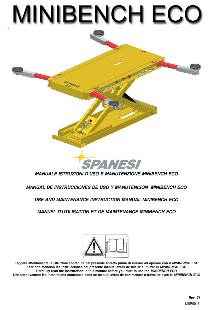
spanesi 100 - H 100/6m Series Guide

SERIE 100 H100/6m
LIBR0055
REVA02
ISTRUZIONI PER L'USO, MANUTENZIONE E RICAMBI
OPERATION, SERVICE ANO SPARE PARTS MANUAL
MODE D'EMPLOI, MAINTENANCE ET PIECES DETACHEES
HANDBUCH FOR BEDIENUNG,WARTUNG UNO ERSATZTEILE
INSTRUCC/ONES PARA EL USO, LA MANUTENCIQN Y LAS PIEZAS DE REPUESTO
Leggere attentamente le istruzioni contenute nel presente libretto prima di iniziare ad operarecon /'attrezzatura
Pleasecarefully readtheinstructions containedin thismanual beforeusingtheequipment
Lire attentivement /es instructions contenues dans ce manuel avant de commencer à travailler avec la machine.
Vor irgendwetchen Arbeiten mit dem gerat die in diesem Handbuch enthaltenen Angaben sorgfaltig lesen
Leer con atenci6n las instrucciones del presente manual antes de iniciar a utilizar et equipo

Serie 100 - H 100/6m
2
SERIE 100 - H 100
BANCO CON SOLLEVATORE
PUNTONE DI TIRO
DIMA UNIVERSALE SUPERSTAR
MISURATORE MC PHERSON
SERIE 100 - H 100
BENCH WITH LIFT
PULL BAR
SUPERSTAR UNIVERSAL JIG
MC PHERSON GAUGE
SERIE 100 - H 100
BANC AVEC ELEVATEUR
ETRESILLON DE TIRAGE
GABARIT UNIVERSEL SUPERSTAR
MESUREUR MC PHERSON
SERIE 100 - H 100
BANK MIT HEBER
ZUGSTREBE
UNIVERSALSCHABLONE SUPERSTAR
MESSGERÄT MC PHERSON
SERIE 100 - H 100
BANCO CON LEVANTADOR
CODAL DE TIRO
PATRÓN UNIVERSAL SUPERSTAR
MEDIDOR MC PHERSON
I
GB
F
D
E

Serie 100 - H 100/6m
3
TRASCRIVERE I DATI RIPORTATI NELLA TARGHETTA DI IDENTIFICAZIONE
DEL BANCO CON SOLLEVATORE
DATI RELATIVI ALLA CONSEGNA DEL BANCO CON SOLLEVATORE
OFFICINE AUTORIZZATE DALLA SPANESI S.p.A.A CUI RIVOLGERSI PER
EVENTUALI INTERVENTI DI ASSISTENZA SUL SOLLEVATORE
MODELLO
PORTATA MAX KG
NUMERO DI SERIE
PRESSIONE OLIO BAR
ANNO COSTRUZIONE
MASSA (PESO) kg
DATA DI CONSEGNA
ORDINE N.
CLIENTE
I

Serie 100 - H 100/6m
4
IN THE BENCH IDENTIFICATION PLATE
INFORMATION CONCERNING DELIVERY OF THE BENCH WITH LIFT
WORKSHOPS AUTHORISED BY SPANESI S.p.A. FOR TECHNICAL SUPPORT
MODEL
MAX CAPACITY IN KG
SERIAL NUMBER
OIL PRESSURE IN BARS:
YEAR OF MANUFACTURE
WEIGHT IN KG
DELIVERY DATE
ORDER NO.
CUSTOMER
GB

Serie 100 - H 100/6m
5
TRANSCRIRE LES DONNEES REPORTEES SUR LA PLAQUE D’IDENTIFICATION DU BANC AVEC ELEVATEUR
DONNEES RELATIVES A LA LIVRAISON DU BANC AVEC ELEVATEUR
ATELIERS AGREES PAR SPANESI S.p.A. OU S’ADRESSER POUR DES REPARATIONS EVENTUELLES
SUR L’ELEVATEUR
MODELE
CHARGE MAX. KG
N° DE SERIE
PRESSION DE L'HUILE EN BARS
ANNEEDECONSTRUCTION
MASSE (POIDS) KG
DATE DE LIVRAISON
COMMANDE N°
CLIENT
F

6
Serie 100 - H 100/6m
D
DIE DATEN AUF DEM GERÄTESCHILD DER BANK MIT HEBER HIER ÜBERTRAGEN
MODELL
MAX TRAGKRAFT kg
SERIENNUMMER
ÖLDRUCK bar
BAUJAHR
MASSE (GEWICHT) kg
LIEFERDATEN FÜR DEN HEBER
VERTRAGSWERKSTATT VON SPANESI S.p.A.,AN DIE SICH FÜR EVENTUELLE
KUNDENDIENST-MAßNAHMEN AM HEBER ZU WENDEN IST
LIEFERDATUM
AUFTRAGSNR.
KUNDE

7
Serie 100 - H 100/6m
TRANSCRIBIR LOS DATOS INDICADOS EN LA ETIQUETA DE IDENTIFICACIÓN DEL BANCO CON LEVANTADOR
DATOS RELATIVOS A LA ENTREGA DEL BANCO CON LEVANTADOR
TALLERES AUTORIZADOS POR SPANESI S.p.A. A LOS QUE DIRIGIRSE PARA
EVENTUALES INTERVENCIONES DE ASISTENCIA PARA EL LEVANTADOR
MODELO
CAPACIDAD MÁX KG
NÚMERO DE SERIE
PRESIÓN DE ACEITE BAR
AÑO DE CONSTRUCCIÓN
MASA (PESO) Kg
FECHA DE ENTREGA
ORDEN N
CLIENTE
E

8
GB
INDICE CONTENTS
INDICE
CONTENTS
INDEX
INHALT
ÌNDICE
Serie 100 - H 100/6m
I
I
GB
F
D
E
SEZIONE 1
DESCRIZIONE E CARATTERISTICHE
PRINCIPALI...............................................14
SECTION 1
1
DESCRIPTION AND MAIN FEATURES: . 14
INTRODUCTION:..............................................14
1INTRODUZIONE................................................14 1.1 WARRANTY........................................................... 16
1.1
GARANZIA..............................................................16
1.1.1
ITEMS EXCLUDED FROM
1.1.1 ESCLUSIONI DALLA GARANZIA . . . 16 THE WARRANTY............................................... 16
1.2
LA CERTIFICAZIONE CE ..............................18
1.2
EC CERTIFICATION.......................................... 18
1.3 DESTINAZIONE D'USO................................18 1.3 APPLICATION....................................................... 18
1.4 IDENTIFICAZIONE.............................................20 1.4 IDENTIFICATION: ..............................................20
1.5
DESCRIZIONE.......................................................22
1.5
DESCRIPTION:...................................................... 22
1.6 LIVELLO SONORO ...........................................34 1.6 NOISE LEVEL:......................................................... 34
1.7 DATI TECNICI.........................................................36 1.7 TECHNICAL SPECIFICATIONS:...............36
SEZIONE 2
2
NORME DI SICUREZZA E PREVENZIONE
INFORTUNI...............................................40
LIVELLI DI PERICOLO:.....................................40
SECTION 2
2
SAFETY PRECAUTIONS AND ACCIDENT
PREVENTION: ..........................................40
HAZARD LEVELS:...............................................40
2.1 SEGNALI DI SICUREZZA..............................44 2.1 SAFETY NOTICES:....................................................44
2.2 ABBIGLIAMENTO ...............................................44 2.2 CLOTHING:.....................................................................44
2.3
ECOLOGIA ED INQUINAMENTO. . . 44
2.3
ECOLOGY AND CONTAMINATION:44
2.4 USO IN SICUREZZA ........................................46 2.4 SAFE USE:.................................................................. 46
2.5 SICUREZZA
NELLA MANUTENZIONE ...........................50
2.5 SAFE MAINTENANCE: ................................... 50
SEZIONE 3
3
TRASPORTO, SCARICO E MESSA IN
SERVIZIO ...................................................52
TRASPORTO E SCARICO............................52
SECTION 3
3
TRANSPORT, UNLOADING AND
INSTALLATION:..................................52
TRANSPORT AND UNLOADING . . . 52
3.1 DISIMBALLO ...........................................................52 3.1 UNPACKING:.................................................................52
3.2
INSTALLAZIONE.................................................52
3.2
INSTALLATION:...........................................................52
3.2.1 AREA D'INSTALLAZIONE...........................54 3.2.1 INSTALLATION AREA:.....................................54
3.2.2
PRIMA DELLA POSA IN OPERA .............54
3.2.2
BEFORE INSTALLATION:...................................54
3.2.3 POSA IN OPERA .................................................56 3.2.3 SETTING UP: .......................................................... 56
3.3 ALLACCIAMENTI................................................58 3.3 CONNECTIONS:................................................ 58
3.3.1
3.3.2
COLLEGAMENTO IMPIANTO
OLEODINAMICO...............................................58
COLLEGAMENTO IMPIANTO
3.3.1
3.3.2
HYDRAULIC SYSTEM
CONNECTION:................................................... 58
PNEUMATIC SYSTEM
3.3.3
PNEUMATICO..............................................................58
COLLEGAMENTO IMPIANTO 3.3.3
CONNECTION:................................................... 58
ELECTRICAL SYSTEM
3.3.3.1
ELETTRICO ..............................................................62
COLLEGAMENTO ALLA RETE DI 3.3.3.1
CONNECTION:...................................................62
CONNECTIONTO THE MAINS: ............62
DISTRIBUZIONE..................................................62
3.3.3.2
CHECKING MOTOR POLARITY: ............ 66
3.3.3.2 VERIFICA POLARITÀ' MOTORE..................66 3.4 ASSEMBLY PROCEDURE:............................. 68
3.4 PROCEDURA DI MONTAGGIO...............68 3.4.1 SAFETY CABLES:.................................................. 68
3.4.1
FUNI DI SICUREZZA........................................68
3.4.2
SAFETY DEVICES: ............................................... 70
3.4.2 SICUREZZE..............................................................70
SEZIONE 4
ISTRUZIONI D'USO ...........................72
SECTION 4
OPERATING INSTRUCTIONS:.........72
4
PRIMA DELL'USO ...............................................72
4
BEFORE USE: .......................................................... 72
4.1 VERIFICA FUNZIONAMENTO 4.1 SAFETY DEVICE EFFICIENCY TEST: . . 72
DISPOSITIVI DI SICUREZZA.......................72
4.1.1
EMERGENCY BUTTON.................................72
4.1.1 PULSANTE DI EMERGENZA......................72 4.1.2 RESET BUTTON: ................................................. 72
4.1.2 PULSANTE DI RIPRISTINO..........................72 4.2 USING THE BENCH:......................................... 74
4.2
USO BANCO DI RISCONTRO................74
4.2.1
RAISING THE LIFT .............................................. 76
4.2.1 SALITA SOLLEVATORE.............................................76 4.2.2 LOWERING THE LIFT...................................... 76
4.2.2
DISCESA SOLLEVATORE.......................................76
4.2.3
POSITIONING THE VEHICLE
4.2.3 SALITA DEL VEICOLO
(DISTRIBUZIONE DEI PESI).........................78 4.3
(WEIGHT DISTRIBUTION):.........................78
LOADS:....................................................................... 78
4.3
PORTATE.....................................................................................78
4.3.1
4.3.1 POSIZIONAMENTO 4.3.2
4.3.3
POSITION OF THE ELEMENTS:............... 82
4.3.2 4.3.4 POSITION OF THE VEHICLE:.....................82
4.3.3 4.3.4.1 MINIMUM DISTANCE OF VEHICLE
4.3.4
POSIZIONE DEL VEICOLO .........................82
FROM EDGE: ..........................................................84
4.3.4.1
4.3.5
DISTANZA MINIMA DEL VEICOLO
DAL BORDO..........................................................84
CONDIZIONI
4.3.5
4.3.6
TYPICAL
OPERATING CONDITIONS:..................... 84
RATED CAPACITY:...................................................86
TIPICHE DI UTILIZZO.....................................84 4.3.7 EFFECTIVE CAPACITY:.........................................92
4.3.6
PORTATA NOMINALE ....................................86
4.3.8
4.3.7 PORTATA EFFETTIVA .......................................92
4.4 USING THE PULL SYSTEM:.......................110

9
Serie 100 - H 100/6m
INDICE INHALT IÌNDICE
SECTION 1
DESCRIPTION ET PRINCIPALES
CARACTERISTIQUES ............................ 15
ABSCHNITT 1
BESCHREIBUNG UND
HAUPTEIGENSCHAFTEN ................ 15
SECCIÓN 1
DESCRIPCIÓN Y CARACTERÍSTICAS
PRINCIPALES...............................................15
1
INTRODUCTION ...............................................15
1
EINFÜHRUNG.......................................................15
1
INTRODUCCIÓN...............................................15
1.1 GARANTIE ...............................................................17 1.1 GARANTIE............................................................... 17 1.1 GARANTÍA...............................................................17
1.1.1
EXCLUSIONS DE LA GARANTIE...........17
1.1.1
GARANTIEAUSNAHMEN............................17
1.1.1
EXCLUSIONES DE LA GARANTÍA . . 17
1.2 LE LABEL CE............................................................19 1.2 CE-ZERTIFIZIERUNG........................................ 19 1.2 LA CERTIFICACIÓN CE .................................19
1.3 USAGE PREVU ......................................................19 1.3 GEBRAUCHSBESTIMMUNG....................... 19 1.3 DESTINACIÓN DE USO................................19
1.4
IDENTIFICATION................................................21
1.4
KENNZEICHNUNG ..........................................21
1.4
IDENTIFICACIÓN................................................21
1.5 DESCRIPTION .......................................................23 1.5 BESCHREIBUNG.................................................. 23 1.5 DESCRIPCIÓN.......................................................23
1.6
NIVEAU DE BRUIT.............................................35
1.6
GERÄUSCHPEGEL .............................................35
1.6
NIVEL DE RUIDO................................................35
1.7
DONNEES TECHNIQUES.............................37
1.7
TECHNISCHE DATEN..............................................37
1.7
DATOS TÉCNICOS .............................................37
SECTION 2
NORMES DE SECURITE ET DE
PREVENTION DES ACCIDENTS ......... 41
ABSCHNITT 2
SICHERHEITSVORSCHRIFTEN UND
UNFALLVERHÜTUNG.......................41
SECCIÓN 2
NORMAS DE SEGURIDAD Y PREVENCIÓN
DE ACCIDENTES..................................... 41
2NIVEAUX DE RISQUE.....................................41 2GEFAHRENSTUFEN.......................................... 41 2NIVELES DE PELIGRO..................................... 41
2.1 SIGNAUX DE SECURITE...............................45 2.1 SICHERHEITSSYMBOLE.................................. 45 2.1 SEÑALES DE SEGURIDAD ...........................45
2.2
HABILLEMENT.......................................................45
2.2
KLEIDUNG ............................................................... 45
2.2
VESTUARIO ............................................................ 45
2.3 ECOLOGIE ET POLLUTION ......................45 2.3 ÖKOLOGIE UND 2.3 ECOLOGÍA Y CONTAMINACIÓN. . . 45
2.4
EMPLOI EN TOUTE SECURITE..................47
UMWELTBELASTUNG ...................................45
2.4
USO EN CONDICIONES DE
2.5 MAINTENANCE 2.4 SICHERE BENUTZUNG................................. 47 SEGURIDAD ........................................................... 47
EN TOUTE SECURITE.......................................51 2.5 SICHERHEIT BEI DER WARTUNG . . . 51 2.5 SEGURIDAD EN LA
MANUTENCIÓN................................................ 51
SECTION 3
TRANSPORT, DECHARGEMENT ET MISE
ABSCHNITT 3
TRANSPORT, ABLADEN UND
SECCIÓN 3
TRANSPORYE, DESCARGA Y PUESTA EN
EN SERVICE......................................... 53
INSTALLATION .................................. 53
FUNCIONAMIENTO...........................53
3TRANSPORT ET DECHARGEMENT . 53 3TRANSPORT UND ABLADEN................. 53 3TRANSPORTE Y DESCARGA.................... 53
3.1 DEBALLAGE............................................................53 3.1 AUSPACKEN...........................................................................53 3.1 DESEMBALAJE ....................................................... 53
3.2
INSTALLATION....................................................................53
3.2
INSTALLATION...................................................................53
3.2
INSTALACIÓN..............................................................53
3.2.1 ZONE D’INSTALLATION.............................55 3.2.1 INSTALLATIONSBEREICH........................... 55 3.2.1 ÁREA DE INSTALACIÓN............................. 55
3.2.2 CONTROLES AVANT LA POSE ..............57 3.2.2 VOR DEM INSTALLIEREN............................ 57 3.2.2 ANTES DE LA INSTALACIÓN ................. 57
3.2.3
POSE .............................................................................59
3.2.3
AUFSTELLEN .......................................................... 59
3.2.3
PUESTA EN FUNCIONAMIENTO . . . 59
3.3 RACCORDEMENTS ET 3.3 ANSCHLÜSSE....................................................... 61 3.3 CONEXIONES...................................................... 61
BRANCHEMENTS...............................................61
3.3.1
ANSCHLUSS AN
3.3.1
CONEXIÓN DE LA INSTALACIÓN
3.3.1 RACCORDEMENT CIRCUIT DIE HYDRAULIK.................................................. 61 OLEODINÁMICA ............................................... 61
HYDRAULIQUE....................................................61 3.3.2 ANSCHLUSS AN DIE PNEUMATIK . . 61 3.3.2 CONEXIÓN DE LA INSTALACIÓN
3.3.2
RACCORDEMENT CIRCUIT
3.3.3
ANSCHLUSS AN DIE ELEKTRIK...............63
NEUMÁTICA.......................................................... 61
PNEUMATIQUE...........................................................61 3.3.3.1 ANSCHLUSS AN DAS 3.3.3 CONEXIÓN DE LA INSTALACIÓN
3.3.3
BRANCHEMENT INSTALLATION
STROMNETZ......................................................... 63
ELÉCTRICA.............................................................. 63
ELECTRIQUE...........................................................63 3.3.3.2 PRÜFEN DER MOTOR-POLUNG ..........65 3.3.3.1 CONECCIÓN A LA RED DE
3.3.3.1 RACCORDEMENT AU RESEAU DE 3.4 MONTAGE...............................................................................69 DISTRIBUCIÓN .................................................... 63
DISTRIBUTION .....................................................63
3.4.1
SICHERHEITSSEILE .............................................69
3.3.3.2
COMPROBACIÓN DE LA
3.3.3.2 CONTROLE POLARITE 3.4.2 SICHERHEITSVORRICHTUNGEN..........71 POLARIDAD DEL MOTOR.................................65
DU MOTEUR.................................................................65
3.4
PROCEDIMIENTO DE MONTAJA . . . 69
3.4 PROCEDURE DE MONTAGE ......................69 3.4.1 CABLES DE SEGURIDAD ............................. 69
3.4.1 CABLES DE SECURITE ....................................69 3.4.2 DISPOSITIVOS DE SEGURIDAD............. 71
3.4.2
PROTECTIONS DE SECURITE..................71
SECTION 4
MODE D'EMPLOI................................ 73
ABSCHNITT 4
BEDIENUNGSANLEITUNG .......... 73
SECCIÓN 4
INSTRUCCIONES DE OPERACIÓN . . . 73
4
AVANT L’EMPLOI......................................................73
4
VOR GEBRAUCH................................................73
4
ANTES DE LA UTILIZACIÓN ................... 73
4.1 CONTROLE FONCTIONNEMENT DES 4.1 PRÜFEN DER 4.1 COMPROBACIÓN DEL
DISPOSITIFS D’URGENCE............................73 FUNKTIONSTÜCHTIGKEIT DER FUNCIONAMIENTO DE LOS
4.1.1
BOUTON D’URGENCE.................................73
SICHERHEITSVORRICHTUNGEN.......... 73
DISPOSITIVOS DE SEGURIDAD............. 73
4.1.2 BOUTON DE REMISE A ZERO ................73 4.1.1 NOT-AUS-SCHALTER ...........................................73 4.1.1 INTERRUPTOR DE EMERGENCIA . . . 73
4.2
UTILISATION DU
4.1.2
RESET-DRUCKKNOPF.....................................73
4.1.2
INTERRUPTOR DE REPOSICIÓN .......... 73
BANC DE MESURE ............................................75 4.2. BENUTZEN DER BANK.................................75 4.2 USO DEL BANCO DE REVISIÓN . . . 75
4.2.1 MONTEE DE L’ELEVATEUR.................................77 4.2.1 AUFWÄRTSBEWEGEN 4.2.1 SUBIDA DEL LEVANTADOR.........................77
4.2.2
DESCENTE DE L’ELEVATEUR...........................77
DES HEBERS............................................................ 77
4.2.2
BAJADA DEL LEVANTADOR........................77
4.2.3 MONTEE DU VEHICULE 4.2.2 ABWÄRTSBEWEGEN DES HEBERS . . 77 4.2.3 SUBIDA DEL VEHÍCULO
(REPARTITION DES POIDS).......................79
4.2.3
ANORDNEN DES FAHRZEUGS
(DISTRIBUCIÓN DE LOS PESOS): . . . 79
4.3 CHARGES .................................................................79 (GEWICHTSVERTEILUNG): ........................ 77 4.3 CARGAS.................................................................... 79
4.3.1 POSITIONNEMENT DU SYSTEME DE 4.3.
LADEGEWICHT
............................................. 79 4.3.1 COLOCACIÓN
4.3.1
4.3.2 4.3.2 4.3.2
4.3.3
POSITION DES ELEMENTS.........................83
4.3.3
POSITION DER TEILE....................................... 83
4.3.3
POSICIÓN DE LOS ELEMENTOS.......... 83
4.3.4 POSITION DU VEHICULE.............................83 4.3.4 POSITION DES FAHRZEUGS.................... 83 4.3.4 POSICIÓN DEL VEHÍCULO.........................83
4.3.4.1 DISTANCE MINIMUM DU VEHICULE 4.3.4.1 MINDESABSTAND DES FAHRZEUGS 4.3.4.1 DISTANCIA MÍNIMA DEL VEHÍCULO
DU BORD.................................................................85
VON DER AUßENKANTE............................ 85
DEL BORDE............................................................ 85
4.3.5 CONDITIONS TYPIQUES 4.3.5 TYPISCHE 4.3.5 CONDICIONES TÍPICAS DE
D’UTILISATION ....................................................85
ARBEITSBEDINGUNGEN.............................. 85
UTILIZACIÓN........................................................ 85
F
DSEP

10
Serie 100 - H 100/6m
GB
INDICE CONTENTS
4.4 UTILIZZO SISTEMA DI TIRO...................110
SEZIONE 5
DISPOSITIVI DI SICUREZZA ..........114
5DISPOSITIVI DI SICUREZZA....................114
5.1 SICUREZZA MECCANICA
ANTIRITORNO .................................................114
5.2 VALVOLA DI BLOCCO PILOTATA . . 114
5.3 VALVOLA DI BLOCCO
DI SICUREZZA...................................................116
5.4 VALVOLA LIMITATRICE DI PRESSIONE
SOLLEVATORE.................................................................116
5.5 VALVOLA LIMITATRICE DI PRESSIONE
POMPA OLEOPNEUMATICA.................116
5.6 PULSANTE ARRESTO
DI EMERGENZA................................................118
5.7 PULSANTE DI RIPRISTINO.......................118
5.8 CIRCUITO ELETTRICO AUSILIARIO DI
COMANDO IN BASSA TENSIONE . 118
5.9 SALVAMOTORE
MAGNETOTERMICO .........................................118
5.10 SEGNALI DI AVVISO
DI SICUREZZA...................................................118
SEZIONE 6
ACCESSORI ........................................120
6ACCESSORI A RICHIESTA.........................120
SEZIONE 7
IMPIANTI........................................120
7IMPIANTI.................................................................120
7.1 SCHEMA OLEODINAMICO....................120
7.2 SCHEMA PNEUMATICO............................126
7.3 SCHEMA ELETTRICO ...................................126
SEZIONE 8
MANUTENZIONE.........................130
8MANUTENZIONE...........................................130
8.1 MANUTENZIONE ORDINARIA...........130
8.2 MANUTENZIONE
STRAORDINARIA............................................134
8.3 ACCANTONAMENTO...............................134
8.4 ROTTAMAZIONE.........................................................134
SEZIONE 9
RICERCA GUASTI.............................136
9GUASTI, CAUSE E RIMEDI.........................136
SEZIONE 10 PARTI DI RICAMBIO.......................142
10 LISTA DEI COMPONENTI
E PARTI DI RICAMBIO..................................142
SECTION 5
SAFETY DEVICES ......................................
114
5SAFETY DEVICES: ............................................ 114
5.1 NON-RETURN MECHANICAL
SAFETY DEVICE: ............................................... 114
5.2 CONTROLLED LOCK VALVE:.....................114
5.3 SAFETY LOCK VALVE:............................................116
5.4 LIFT PRESSURE RELIEF VALVE:.....................116
5.5 OLEOPNEUMATIC PUMP PRESSURE
RELIEF VALVE:.....................................................................116
5.6 EMERGENCY STOP BUTTON:.............. 118
5.7 RESET BUTTON: .............................................. 118
5.8 LOW VOLTAGE AUXILIARY
ELECTRICAL CONTROL CIRCUIT: . 118
5.9 MAGNETOTHERMAL
OVERLOAD CUT-OUT .................................. 118
5.10 SAFETY WARNING NOTICES:.............. 118
SECTION 6
ACCESSORIES: ...........................................
120
6ACCESSORIES ON REQUEST................ 120
SECTION 7
SYSTEMS: .....................................................
120
7SYSTEMS................................................................. 120
7.1 HYDRAULIC DIAGRAM:............................ 120
7.2 PNEUMATIC DIAGRAM:............................. 126
7.3 WIRING DIAGRAM:....................................... 126
SECTION 8
MAINTENANCE: ..........................................
130
8MAINTENANCE:.............................................. 130
8.1 ROUTINE MAINTENANCE: .................... 130
8.2 EXTRAORDINARY MAINTENANCE:134
8.3 LONG-TERM STORAGE:............................... 134
8.4 SCRAPPING ......................................................... 134
SECTION 9
TROUBLESHOOTING:................................
137
9. FAULTS, CAUSES
AND SOLUTIONS:......................................... 137
SECTION 10 SPARE PARTS:................................................
142
10. COMPONENTS AND
SPARE PARTS LIST ........................................... 142
I

11
Serie 100 - H 100/6m
INDICE INHALT ÌNDICE
4.3.6 CHARGE NOMINALE .....................................87
4.3.7 CHARGE EFFECTIVE.........................................93
4.3.8
4.4 UTILISATION DU
SYSTEME DE TIRAGE ....................................111
4.3.6 NENNTRAGKRAFT........................................... 87
4.3.7 EFFEKTIVE TRAGKRAFT.................................. 93
4.3.8
4.4 BENUTZEN DES ZUGSYSTEMS........... 111
4.3.6 CAPACIDAD NOMINAL................................87
4.3.7 CAPACIDAD EFECTIVA..................................93
4.3.8
4.4 UTILIZACIÓN DEL
SISTEMA DE TIRO ............................................111
SEZIONE 5
DISPOSITIFS DE SECURITE ........... 115
ABSCHNITT 5
SICHERHEITSVORRICHTUNGEN
.... 115
SECCIÓN 5
DISPOSITIVOS DE SEGURIDAD.....115
5
DISPOSITIFS DE SECURITE.......................115
5
SICHERHEITSVORRICHTUNGEN . . 115
5
DISPOSITIVOS DE SEGURIDAD...........115
5.1
5.2
SECURITE MECANIQUE ANTI-RETOUR
115
SOUPAPE DE BLOCAGE PILOTEE . 115
5.1
5.2
MECHANISCHE RÜCKSCHLAG
-
SICHERHEITSVORRICHTUNG
..............115
GESTEUERTES
SPERRVENTIL................. 115
5.1
5.2
DISPOSITIVO DE SEGURIDAD
MECÁNICA CON RETENCIÓN...........115
VÁLVULA DE BLOQUEO
5.3 SOUPAPES DE BLOCAGE DE 5.3
SICHERHEITSSPERRVENTIL . . . . . . . . . . .
CONTROLADA ................................................115
SECURITE...............................................................117
5.4
ÜBERDRUCKVENTIL HEBER................... 117
5.3
VÁLVULA DE BLOQUEO DE
5.4
5.5
SOUPAPE DE LIMITATION DE LA
PRESSION DE L’ELEVATEUR..........................117
SOUPAPE DE LIMITATION DE LA
5.5
5.6.
ÜBERDRUCKVENTIL
ÖLHPNEUMATISCHE
PUMPE...............117
NOT
-AUS-SCHALTER.......................................119
5.4
SEGURIDAD .........................................................117
VÁLVULA LIMITADORA DE PRESIÓN
DEL LEVANTADOR.............................................117
PRESSION DE LA POMPE 5.7.
RESET
-DRUCKKNOPF.................................. 119 5.5 VÁLVULA LIMITADORA DE PRESIÓN
5.6
OLEOPNEUMATIQUE .................................117
BOUTON D’ARRET D’URGENCE . . 119
5.8
NIEDERSPANNUNGS-
BETRIEBSSTROMSTEUERKREIS
..............119
DE LA BOMBA
OLEONEUMÁTICA.........................................117
5.7
BOUTON DE REMISE A ZERO .............119
5.9
MAGNETOTHERMISCHER
5.6
INTERRUPTOR DE PARADA DE
5.8 CIRCUIT ELECTRIQUE AUXILIAIRE
DE COMMANDE 5.10
ÜBERLASTSCHUTZ
.......................................119
SICHERHEITS
-WARNHINWEISE . . . 119 5.7
EMERGENCIA......................................................119
INTERRUPTOR DE REPOSICIÓN. . . 119
5.9
5.10
EN BASSE TENSION ......................................119
COUPE-CIRCUIT
MAGNETOTHERMIQUE ............................119
SIGNAUX DE SECURITE............................119
5.8
5.9
5.10
CIRCUITO ELÉCTRICO AUXILIAR DE
MANDO EN BAJA TENSIÓN..................119
CORTACIRCUITOS
MAGNETOTÉRMICO..........................................119
SEÑALES DE AVISO
DE SEGURIDAD................................................119
SECTION 6
ACCESSOIRES................................... 121
ABSCHNITT 6
ZUBEHÖR ...................................... 121
SECCIÓN 6
ACCESORIOS.....................................121
6ACCESSOIRES SUR DEMANDE . . . 121 6
ZUBEHÖR
AUF ANFRAGE.......................121 6.0 ACCESORIOS PREVIA SOLICITUD . 121
SECTION 7
7
INSTALLATIONS.............................. 121
INSTALLATIONS.....................................................121
ABSCHNITT 7
7
SYSTEME
........................................ 121
SYSTEME
................................................................. 121
SECCIÓN 7
INSTALACIONES..............................121
7.1
SCHEMA HYDRAULIQUE.........................121
7.1
ÖLHYDRAULIK.................................................. 121
7
INSTALACIONES.....................................................121
7.2 SCHEMA PNEUMATIQUE.........................127 7.2
PNEUMATIK
.................................................................127 7.1 ESQUEMA OLEODINÁMICO.................121
7.3 SCHEMA ELECTRIQUE................................127 7.3
ELEKTRIK
................................................................. 127 7.2 ESQUEMANEUMÁTICO.............................127
7.3
DIAGRAMA ELÉCTRICO............................127
SECTION 8
MAINTENANCE................................ 131
ABSCHNITT 8
WARTUNG.........................................131
SECCIÓN 8
MANUTENCIÓN ...............................131
8MAINTENANCE................................................131 8
WARTUNG
..................................................................131 8MANUTENCIÓN..............................................131
8.1
MAINTENANCE COURANTE...............131
8.1
NORMALE WARTUNG .............................. 131
8.1
MANUTENCIÓN ORDINARIA..............131
8.2 MAINTENANCE SUPPLEMENTAIRE 135 8.2
BESONDERE
WARTUNG..........................135 8.2 MANUTENCIÓN
8.3
MISE HORS SERVICE .....................................135
8.3
LANGZEITLAGERUNG...............................135
EXTRAORDINARIA........................................135
8.4
DEMOLITION .....................................................135
8.4
VERSCHROTTUNG ....................................... 135
8.3
8.4
ALMACENAMIENTO A LARGO
TÉRMICO................................................................135
DESGUACE...................................................................135
SECTION 9
RECHERCHE DES PANNES ............ 138
ABSCHNITT 9
FEHLERSUCHE .............................139
SECCIÓN 9
LOCALIZACIÓN DE FALLOS .........140
9. PANNES, CAUSES ET SOLUTIONS . 138 9
STÖRUNGEN, URSACHEN UND
MAßNAHMEN
................................................... 139
9.0 FALLOS, CAUSAS Y SOLUCIONES . 140
SECTION 10
PIECES DETACHEES ....................... 143
ABSCHNITT 10
ERSATZTEILE................................ 143
SECCIÓN 10
PIEZAS DE REPUESTO....................143
10 LISTE DES COMPOSANTS ET DES
PIECES DETACHEES..................................................143
10
LISTE DER KOMPONENTEN UND
ERSATZTEILE..............................................................143
10 LISTA DE COMPONENTES Y PIEZAS
DE REPUESTO...........................................................143
F
DE

12
Serie 100 - H 100/6m
SI RISERVA LA PROPRIETA' DEL SEGUENTE LIBRETTO,VIETA
S.p.A.
LA SOTTOSCRITTA DITTA
THE COMPANY
LA SOCIETE SOUSSIGNEE
DIE FIRMA
LA EMPRESA
SI RISERVA LA PROPRIETÀ DEL SEGUENTE LIBRETTO,VIETA
A CHIUNQUE DI RIPRODURLO O DI COMUNICARLO A TERZI SENZA
L'AUTORIZZAZIONE DELLA PROPRIETARIA E SI RISERVA
LA FACOLTÀ DI TUTELARE I PROPRI DIRITTI PERSEGUENDO
I TRASGRESSORI A TERMINI DI LEGGE.
RESERVES OWNERSHIP OF THIS MANUAL, FORBIDS REPRODUCTION
OR COMMUNICATION THEREOF TO THIRD PARTIES WITHOUT
THE AUTHORISATION OF THE OWNER AND RESERVES THE POWER TO
SAFEGUARD ITS RIGHTS BY PROSECUTING ALL TRANSGRESSORS
IN ACCORDANCE WITH THE LAW.
SE RESERVE LA PROPRIETE DE CE MANUEL.
ELLE INTERDIT A QUICONQUE DE LE REPRODUIRE OU DE LE COMMUNIQUER A TIERS
SANS L’AUTORISATION DU PROPRIETAIRE ET SE RESERVE
LA FACULTE DE DEFENDRE SES DROITS EN POURSUIVANT LES
TRANSGRESSEURS AUX TERMES DE LA LOI.
BEHÄLT SICH DIE RECHTE AN DIESEM HANDBUCH VOR UND ERKLÄRT
FÜR UNZULÄSSIG DIE VERVIELFÄTIGUNG ODER VERBREITUNG AN DRITTE OHNE AUSDRÜCKLICHE GENEHMIGUNG.
DES WEITEREN SCHÜTZT SIE IHRE RECHTE UND KANN VERSTÖßE GESETZESMÄßIG AHNDEN.
SE RESERVA LA PROPIEDAD DEL PRESENTE MANUAL, PROHIBE
A QUIENQUIERA REPRODUCIRLO O COMUNICARLO A TERCEROS SIN
LA AUTORIZACIÓN DE LA PROPIETARIA Y SE RESERVA
LA FACULTAD DE TUTELAR SUS DERECHOS, DEMANDANDO A
LOS TRANSGRESORES DE ACUERDO CON LA LEY.

Serie 100 - H 100/6m
13

14
Serie 100 - H 100/6m
SEZIONE 1
DESCRIZIONE E CARATTERISTICHE PRINCIPALI
SECTION 1
DESCRIPTION AND MAIN FEATURES
1 INTRODUZIONE
Il presente libretto contiene le istruzioni per l'installazione e quanto
necessario per la conoscenza, il buon uso e la normale manutenzione delle
apparecchiature per la riparazione di veicoli sinistrati denominate BANCO
DI RADDRIZZATURA E TIRO SERIE 100 - H 100/6m, fabbricate
dalla SPANESI S.p.A. di San Giorgio delle Pertiche (Padova) - Italia.
Nel seguito della descrizione le apparecchiature verranno più semplicemente
denominate SERIE 100 - H 100. Quanto riportato di seguito non
costituisce una descrizione completa dei vari organi delle attrezzature e tanto
meno un'esposizione dettagliata del loro funzionamento. L'utilizzatore però
troverà qui contenuto quanto è utile conoscere per l'uso in sicurezza e per
una buona conservazione delle macchine.
La SERIE 100 - H 100 si compone essenzialmente delle seguenti parti:
Sollevatore a pantografo, banco con ruote, sistema di tiro e dima.
La SPANESI S.p.A. ha predisposto il presente libretto generale per l'uso
della SERIE 100 - H 100 e un libretto d'istruzioni per la pompa del braccio
di tiro. Si raccomanda quindi di leggere innanzitutto le istruzioni contenute nel
presente libretto e poi di consultare le istruzioni contenute nel libretto della
pompa e del verricello (se fornito in dotazione):
Dal rispetto e dall'esatta osservanza delle istruzioni descritte in questo
libretto, dipende la sicurezza dell'operatore, il regolare funzionamento,
l'economia di esercizio e la durata del sollevatore e del sistema di tiro. E'
obbligatorio attenersi a quanto descritto nel presente libretto:
AVVERTENZA
1 INTRODUCTION
This manual contains instructions for installation and all information necessary
for knowledge, correct use and routine maintenance of the equipment for
the repair of damaged vehicles called SERIE 100 - H 100/6m
STRAIGHTENING AND PULL BENCH manufactured by SPANESI
S.p.A. of San Giorgio delle Pertiche (Padova) - Italy.
In this description the equipment will be referred to simply as SERIE 100 -
H 100. The following does not aim to provide a complete description of the
various parts of the machine or give a detailed account of how they operate
but the user will find everything he needs to know for safe use and correct
care.
The SERIE 100 - H 100 consists basically of the following parts: scissor
lift, bench with wheels, pull system and jig.
SPANESI S.p.A. provides this general manual for use of the SERIE 100 - H
100 and a specific instruction manual for the pull arm pump.You should
therefore firstly read the instructions contained in this manual and then consult
the instructions in the manual for the pump and winch (if provided).
The instructions given in this manual must be followed to ensure user safety,
correct operation, economic running and long life of the lift and pull system.
It is of fundamental importance to observe all the directions given in this
manual:
SPANESI S.p.A. declines all liability for damage, both direct and
indirect, to persons, animals or property due to negligence or
La SPANESI S.p.A. declina qualsiasi responsabilità per danni
diretti o indiretti, arrecati a persone, animali o cose, che siano
provocati dalla negligenza o dalla mancata osservanza di quanto
contenuto nelle istruzioni d'uso.
failure to comply with these instructions.
Il presente libretto è parte integrante del prodotto, deve essere
custodito con cura per permetterne l'integrità e la consultazione
durante tutto il periodo di vita della macchina.
Ulteriori copie del libretto d'istruzione sono disponibili previa richiesta a:
via Praarie, 56/II - Località Cavino
35010 SAN GIORGIO DELLE PERTICHE (PADOVA) - ITALIA
This manual forms an integral part of the product
and must be carefully kept
and consulted throughout the life of the machine.
Further copies can beobtained upon request from:
Il presente libretto viene accompagnato dai libretti d'uso e manutenzione
del sollevatore a pantografo, della pompa idropneumatica e del verricello
elettrico, nel caso in cui venga eventualmente fornito in dotazione.
Ce manuel fait partie intégrante de la machine et doit être conservé
soigneusement pour le garder en bon état et pouvoir
le consulter en cas de besoin.
Pour obtenir d’autres copies de ce manuel, en faire
la demande à l’adresse suivante:
This manual is accompanied by the operation and service manuals
for the pantograph lift, the hydraulic-pneumatic pump
and the electric winch, if provided.
Ce manuel est accompagné des manuels d’emploi et de maintenance
Das vorliegende Handbuch ist integrierender Teil des Produkts und muss
sorgfältig aufbewahrt werden, damit die Unversehrheit sowie das
Nachschlagen während der gesamten Lebensdauer des Gerätes möglich
sind.Weitere Kopien können auf Anfrage bestellt werden bei:
de
l’élévateur
à pantographe, de la pompe hydr
opneumatique
et du treuil électrique, si celui-ci est fourni avec la machine.
Dem vorliegenden Handbuch liegen die Gebrauchs- und
Wartungsanleitungen bei für Scherenheber,hydraulisch-
pneumatische
Pumpe und Elektrowinde, falls mitgeliefert.
El presente manual es parte integrante del producto, tiene que ser
custodiado con cuidado para permitir la integridad y la consulta durante
todo el período de vida de la
máquina. Ulteriores reproducciones de este
manual de instrucciones están disponibles previa solicitud en:
El presente manual está acompañado por los manuales de uso y
manutención del levantador a pantógrafo, la bomba hidroneumática y del
cabrestante eléctrico, en el caso en que haya sido incluido en la dotación.
I
GB

Serie 100 - H 100/6m
15
SECTION 1
DESCRIPTION ET PRINCIPALES
CARACTERISTIQUES
ABSCHNITT 1
BESCHREIBUNG UND
HAUPTEIGENSCHAFTEN
SECCIÓN 1
DESCRIPCIÓN Y CARACTERÍSTICAS
PRINCIPALES
1 INTRODUCTION
Ce manuel contient les instructions pour
l’installation et tout ce qui est nécessaire pour
bien connaître, utiliser correctement et effectuer
la maintenance normale des appareils pour la
réparation de véhicules accidentés, appelés
BANCS DE REDRESSEMENT ET DE
TIRAGE SERIE 100 - H 100/6m,
fabriqués par SPANESI S.p.A., San Giorgio
delle Pertiche (Padoue) - Italie.
Ces appareils seront tout simplement appelés
SERIE 100 - H 100 dans le reste du manuel. Ce
qui est reporté ci-dessous ne constitue pas une
description complète des différents organes de la
machine et encore moins une présentation
détaillée de son fonctionnement. L’utilisateur y
trouvera néanmoins tout ce qu’il faut savoir pour
utiliser la machine en toute sécurité et bien la
conserver.
La SERIE 100 - H 100 se compose
essentiellement des parties suivantes: Elévateur
à pantographe, banc avec roues, système
de tirage et gabarit.
SPANESI S.p.A. a rédigé ce manuel pour
l’utilisation de la SERIE 100 - H 100 et un
manuel spécifique pour la pompe du bras de
tirage. Il est donc conseillé de lire d’abord les
instructions contenues dans ce manuel et ensuite
de consulter les instructions contenues dans le
manuel de la pompe et du treuil (s’il est fourni
avec la machine).
Suivre scrupuleusement les instructions reportées
dans ce manuel car c’est de cela que dépendent
la sécurité de l’opérateur, le fonctionnement
correct, l’économie d’énergie ainsi que la longévité
de l’élévateur et du système de tirage. Se
conformer obligatoirement à ce qui est décrit
dans ce manuel.
ATTENTION
1 EINFÜHRUNG
Dieses Handbuch enthält die Anweisungen zur
Installation sowie alle erforderlichen Angaben für
Kenntnis, korrekten Gebrauch und normale
Wartung der Geräte zur Reparatur von
Unfallwagen, bezeichnet RICHT und
ZUGBANK SERIE 100 - H 100/6m,
hergestellt von SPANESI S.p.A. aus San Giorgio
delle Pertiche (Padua) - Italien.
In dieser Beschreibung werden die Gerät aus
praktischen Gründen nachfolgend mit SERIE
100 - H 100 bezeichnet. Die nachfolgenden
Angaben stellen weder eine vollständige
Beschreibung noch eine detaillierte Ausführung
des Betriebs der verschiedenen Ausrüstungsteile
dar. Vielmehr findet der Benutzer jedoch hier alle
Angaben, die für den sicheren Gebrauch und eine
korrekte Wartung der Geräte erforderlich sind.
Die SERIE 100 - H 100 setzt sich grundsätzlich
aus folgenden Teilen zusammen: Scherenheber,
Bank mit Rädern, Zugsystem und
Schablone.
Die Firma SPANESI S.p.A. liefert das
vorliegende generelle Handbuch zur Benutzung
der SERIE 100 - H 100 sowie eine
Bedienungsnaleitung für die Pumpe des Zugarms.
Somit sollten zunächst die im vorliegenden
Handbuch enthaltenen Angaben und dann erstdie
Bedienungsanleitung der Pumpe und der Winde
(falls mitgeliefert) sorgfältig gelesen werden.
Das strikte Einhalten der hier angeführten
Hinweise gewährleistet die Sicherheit des
Bedieners, den regulären und wirtschaftlichen
Gerätebetrieb sowie die Lebensdauer von Heber
und Zugsystem. Das Einhalten der hier gemachten
Hinweise ist bindend.
HINWEIS
SPANESI S.p.A. übernimmt keinerlei
Haftung für Schäden an Personen,
1 INTRODUCCIÓN
El presente manual contiene las instrucciones para
la instalación y lo necesario para el conocimiento,
el buen empleo y la normal manutención de los
aparatos para la reparación de vehículos
accidentados denominados BANCO
ENDEREZADOR Y TIRO SERIE 100 - H
100/6m, construido por SPANESI S.p.A. de San
Giorgio delle Pertiche (Padua) - Italia.
En la continuación de la descripción, los equipos
serán denominados sencillamente SERIE 100 -
H 100. Lo indicado enseguida no constituye una
descripción completa de los varios órganos de los
equipos y ni una exposición detallada de su
funcionamiento. No obstante, el explotador
encontrará aquí contenido cuanto le es útil
conocer para la utilización en condiciones de
seguridad y para una buena conservación de las
máquinas.
La SERIE 100 - H 100 está compuesta
principalmente por las siguientes partes:
Levantador a pantógrafo, banco sobre
ruedas, sistema de tiro y patrón.
SPANESI S.p.A. ha predispuesto el presente
manual general para la utilización de la SERIE
100 - H 100 y un manual de instrucciones para
la bomba del brazo de tiro. Se encomienda, por lo
tanto, leer ante todo las instrucciones contenidas
en el presente manual y luego consultar las
instrucciones contenidas en el manual de la
bomba y el cabrestante (si contenidos en la
dotación):
Del respeto y de la exacta observancia de las
instrucciones descritas en este manual, depende la
seguridad del operador, el regular funcionamiento,
la economía de ejercicio y la duración del
levantador y el sistema de tiro. Es obligatorio
atenerse a lo descrito en el presente manual:
ADVERTENCIA
Gegenständen oderTieren, die aufgrund
SPANESI S.p.A. décline toute
responsabilité pour les dommages directs
ou indirects aux personnes, aux animaux
ou aux choses dus à de la négligence ou à
l’inobservation des indications contenues
dans ce manuel.
Nachlässigkeit oder Nichtbeachtung der
im vorliegenden Handbuch enthaltenen
Angaben entstehen können.
SPANESI S.p.A. declina cualquiera
responsabilidad por daños directos o
indirectos a personas, animales o cosas,
provocados por la negligencia o por no
respetar lo contenido en las instrucciones
de utilización.
F
DE

16
Serie 100 - H 100/6m
1.1 GARANZIA
La SPANESI S.p.A. garantisce la SERIE 100 - H 100 ed i suoi accessori
per un periodo di mesi 12 dalla data di acquisto. Tale garanzia si esplica nella
riparazione o sostituzione gratuita di quelle parti che, dopo un attento esame
eseguito dal Servizio Tecnico del Costruttore, risultino difettose con
esclusione di tutte le parti elettriche. La garanzia è limitata ai soli difetti di
materiali e cessa qualora le parti rese risultino manomesse o comunque
smontate da personale non autorizzato allo scopo. Sono escluse dalla
garanzia le responsabilità per danni diretti e indiretti arrecati a persone,
animali o cose a causa del guasto o del malfunzionamento della macchina. Le
spese relative alla sostituzione dei lubrificanti, le spese di trasporto, gli
eventuali tributi doganali, l'IVA e quant'altro non scritto nel contratto di
fornitura sono in ogni caso a carico dell'acquirente. Le sostituzioni o le
riparazioni dei materiali in garanzia non prolungano in ogni caso i termini
della garanzia stessa. L'acquirente potrà comunque far valere i suoi diritti sulla
garanzia solo se avrà rispettato le condizioni concernenti la prestazione della
garanzia, eventualmente riportate nel contratto di fornitura. Qualora risultasse
che le parti non intendono sottoporre a giudizio arbitrale le controversie
nascenti dal contratto di fornitura o in ogni altro caso in cui sia richiesta la
pronuncia da parte di un organo del Foro ordinario, sarà territorialmente
competente solo il Foro di Padova.
1.1.1 ESCLUSIONI DALLA GARANZIA
Alla consegna è necessario verificare che il prodotto non abbia subito danni
durante il trasporto e che la dotazione di accessori sia integra e completa.
Eventuali reclami dovranno essere presentati entro 8 giorni dalla consegna
del sollevatore. Oltre ai casi previsti nel contratto di fornitura la garanzia
decade:
•Qualora si dovesse verificare un errore di manovra imputabile
all'operatore.
•Qualora il danno sia imputabile ad insufficiente manutenzione.
•Qualora venga oltrepassata la portata effettiva prevista nelle tabelle,
sovraccaricando in tal modo la macchina.
•Qualora venga impiegato un braccio di tiro non originale.
•Qualora l'applicazione del braccio di tiro non sia conforme a quanto
previsto nelle presenti istruzioni.
•Qualora la macchina abbia subito cambiamenti ed il danno sia causato da
tali cambiamenti, in seguito ad interventi di riparazione eseguiti
dall'utilizzatore senza il consenso della SPANESI S.p.A. o a causa del
montaggio di pezzi di ricambio non originali.
•Qualora non vengano rispettate le istruzioni descritte nei libretti
d'istruzione.
1.1 WARRANTY
SPANESI S.p.A. warrants the SERIE 100 - H 100 and its accessories for
a period of 12 months from the date of purchase. The userís remedy under
warranty shall consist in the repair and replacement, free of charge, of any
parts - with the exception of all electrical parts - which, subsequent to a
careful examination by the Manufacturerís Technical Servicing Dept., prove
defective. The warranty is limited to defects in materials only, and shall
become void in the event the parts prove to have been tampered with or
nonetheless disassembled by personnel not authorised for the purpose. The
warranty is not applicable to liability for direct or indirect damage to
property or injury of persons or animals resulting from the failure or
malfunctioning of the machine. Expenses relating to the replacement of
lubricants, transport costs, any customs duty, VAT and anything else not
specified in the supply contract shall, in all cases, be at the purchaserís
expense. Under no circumstances shall the replacement or repair of materials
under warranty cause the terms of the actual warranty to be extended. The
purchaser shall nonetheless only be entitled to enforce his claims regarding
the warranty in the event he has complied with the conditions concerning
any warranty terms featured in the supply contract. Should the parties not
intend submitting any dispute arising from the supply contract to an
arbitration panel, or in any other case where judgement is to be rendered by
a body of the ordinary courts, the only court of competent jurisdiction shall
be the Court of Padova.
1.1.1 ITEMS EXCLUDED FROM THE WARRANTY
Upon delivery the purchaser must check that the product has not been
damaged during transport, that all the accessories have been included and
are in perfect condition. Any claims must be submitted within 8 days from
delivery. In addition to the cases provided for in the supply contract, the
warranty will lapse:
If the machine has been used incorrectly by the operator.
•
If the damage is due to insufficient maintenance.
•
If the damage is due to insufficient maintenance.
•
If the effective capacity specified in the tables is exceeded, thus overloading
the machine.
•
If a non-original pull arm is used.
•
If the pull arm has been applied without following the instructions
contained in this manual.
•
If the machine has been altered and the damage has been caused by these
alterations as a result of repair work carried out by the user without the
consent of SPANESI S.p.A. or due to the use of non-original spare
parts.
•
If the instructions given in this manual are not followed.

Serie 100 - H 100/6m
17
1.1 GARANTIE
SPANESI S.p.A. garantit la SERIE 100 - H
100 et ses accessoires pendant 12 mois à
compter de la date d’achat. Cette garantie
consiste à réparer ou à remplacer gratuitement
les parties qui résultent défectueuses après un
examen attentif effectué par le Service technique
du Constructeur, à l’exclusion des parties
électriques. La garantie est limitée aux vices de
matériaux et cesse si les parties ont été altérées
ou démontées par du personnel non autorisé. La
garantie ne couvre pas la responsabilité pour les
dommages directs et indirects aux personnes, aux
animaux ou aux choses dus à une panne ou au
mauvais fonctionnement de la machine. Les frais
relatifs à la vidange des lubrifiants, les frais de
transport, les droits de douane éventuels, la TVA
et tout ce qui n’est pas écrit dans le contrat de
fourniture sont à la charge de l’acheteur. Le
remplacement ou la réparation des pièces sous
garantie ne prolonge en aucun cas les délais de
cette garantie. L’acheteur ne pourra néanmoins
faire valoir ses droits sur cette dernière que s’il a
respecté les conditions concernant la prestation
de la garantie qui sont éventuellement reportées
dans le contrat de fourniture. Le tribunal de
Padoue sera le seul compétent si les parties
n’entendent pas soumettre les litiges dérivant du
contrat de fourniture à un jugement d’arbitre ou
si une décision doit être prise par un organe du
tribunal ordinaire.
1.1.1 EXCLUSIONS DE LA GARANTIE
A la livraison, contrôler si la machine n’a pas subi
de dommages durant le transport, si aucun
accessoire ne manque et s’ils sont en bon état.
Les réclamations éventuelles devront être faites
dans les 8 jours qui suivent la livraison de
l’élévateur. Mis à part ce qui est prévu dans le
contrat de fourniture, la garantie cesse dans les
cas suivants:
•
s’il y a erreur de manœuvre imputable à
l’opérateur,
•
si le dommage est dû à une maintenance
insuffisante,
•
si la charge effective prévue sur les tableaux a
été dépassée, en surchargeant ainsi la machine.
•
si le bras de tirage utilisé n’est pas celui
d’origine.
•
si le montage du bras de tirage n’est pas
conforme à ce qui est prévu dans ce manuel.
•
si la machine a été modifiée et que le dommage
est dû à cette modification, à des réparations
effectuées par l’utilisateur sans l’autorisation de
SPANESI S.p.A. ou au montage de pièces
détachées qui ne sont pas d’origine,
•
si les instructions reportées dans ce manuel ne
sont pas respectées.
1.1 GARANTIE
SPANESI S.p.A. übernimmt für die SERIE
100 - H 100 und Zubehörteile eine
zwölfmonatige Garantie ab Kaufdatum. Diese
Garantie umfasst die kostenlose Reparatur oder
Ersetzung der Teile, die nach eingehender
Prüfungen durch den technischen Kundendienst
des Herstellers als fehlerhaft erachtet werden,
wobei sämtliche elektrischen Teile ausgenommen
sind. Die Garantie ist beschränkt auf
ausschließliche Materialfehler und hat sofortige
Ungültigkeit, falls an den zurückgegebenen Teilen
Manipulierungen oder Demontage, ausgeführt
durch für diese Arbeiten nicht zugelassenes
Personal, festzustellen sind. Von der Garantie
ausgenommen ist die Haftung für direkte oder
indirekte Schäden an Personen, Tieren oder
Gegenständen, die durch Defekte oder Störungen
am Gerät entstehen. Die Kosten für das Ersetzen
von Schmiermitteln, für den Transport, für
Zollabgaben, MwSt. und alle anderen nicht im
Liefervertrag anführten Posten gehen zu Lasten
des Käufers. Das Ersetzen oder Reparieren der
durch Garantie gedeckten Teile verlängern in
keiner Weise die Garantiedauer. Der Kunde kann
in jedem Fall nur bei Einhaltung der ggf. im
Liefervertrag angeführten Bedingungen für die
Garantieleistung Garantieansprüche stellen. Sollten
die Parteien nicht beabsichtigen, die aus dem
Liefervertrag ggf. entstehenden Kontroversen
einem Schiedsspruch unterzuordnen, oder in
jedem anderen Fall, in dem eine gerichtliche
Entscheidung zu treffen ist, hat das Gericht von
Padua alleinige Zuständigkeit.
1.1.1 GARANTIEAUSNAHMEN
Bei der Lieferung muss geprüft werden, dass das
Produkt keinerlei Transportschäden aufweist und
dass die beiliegende Zubehör vollständig sowie
unversehrt ist. Eventuelle Reklamationen müssen
binnen 8 Tagen ab Lieferdatum eingehen.
Zusätzlich zu den im Liefervertrag vorgesehenen
wird die Garantie in folgenden Fällen ungültig:
•
Bei unsachgemäßer Bedienung durch den
Benutzer.
•
Bei Schäden infolge unzureichender Wartung.
•
Bei Übersteigen der in der Tabelle angegebenen
effektiven Tragkraft und somit bei Überlasten
des Gerätes.
•
Bei Verwenden eines nicht originalen Zugarms.
•
Falls die Anwendung des Zugarms nicht den hier
gemachten Angabenentspricht.
•
Bei Änderungen an der Maschine und
darausfolgenden Schäden im Anschluss an vom
Benutzer ohne Zustimmung von SPANESI
S.p.A. ausgeführten Reparaturarbeiten, oder
infolge einer Montage von nicht originalen
Ersatzteilen.
•
Bei Nichteinhaltung der in der
Bedienungsanleitung enthaltenen Angaben.
1.1 GARANTÍA
SPANESI S.p.A. garantiza la SERIE 100 - H
100 y sus accesorios por la duración de 12 meses
desde la fecha de venta. Tal garantía se ejercita en
la reparación o sustitución gratuita de las partes
que, después de un atento examen ejecutado por
el Servicio Técnico del Constructor, resulten
defectuosas con exclusión de todas las partes
eléctricas. La garantía está limitada a los defectos
de materiales y cesa en caso de que las piezas
devueltas resulten violadas o, en todo caso, hayan
sido desmontadas por personal no autorizado a
tal objetivo. Son excluidas de la garantía las
responsabilidades por daños directos e indirectos
a personas, animales o cosas a causa de la avería
o el funcionamiento defectuoso de la máquina.
Los gastos relativos a la sustitución de los
lubricantes, los gastos de transporte, los
eventuales tributos aduaneros, el IVA y demás no
escritos en el contrato de suministro están, en
todo caso, a cargo del comprador. Las
sustituciones o las reparaciones de los materiales
en garantía no alargan, en todo caso, los términos
de la garantía. El comprador podrá sólo imponer
sus derechos sobre la garantía si habrá respetado
las condiciones que conciernen la prestación de la
garantía, eventualmente indicadas en el contrato
de suministro. En caso de que resultara que las
partes no deseen someter a juicio arbitral las
controversias que nacen del contrato de
suministro o en cada otro caso en que sea
solicitada la pronunciación por parte de un
órgano del Foro ordinario, será localmente
competente sólo el Foro de Padua.
1.1.1 EXCLUSIONES DE LA GARANTÍA
En el momento de la entrega es necesario
comprobar que el producto no haya sufrido
daños durante el transporte y que la dotación de
accesorios sea íntegra y completa. Eventuales
reclamaciones tendrán que ser presentadas
dentro de 8 días a partir del momento de la
entrega del levantador. Además de los casos
previstos en el contrato de suministro, la
garantía caduca:
•
En caso de que se produjera un error de
manipulación imputable al operador.
•
En caso de que el daño sea imputable a una
insuficiente manutención.
En caso de que sea superado el alcance efectivo
previsto en las tablas, sobrecargando en tal modo
la máquina.
•
En caso de que sea empleado un brazo de tiro
no original.
•
En caso de que la aplicación del brazo de tiro
no esté conforme a todo lo previsto en las
presentes instrucciones.
•
En caso de que la máquina haya padecido
cambios y el daño sea causado por tales
cambios, sucesivamente a intervenciones de
reparación ejecutadas por el explotador sin el
consentimiento de SPANESI S.p.A. o a causa
del montaje de piezas de repuesto no originales.
•
En caso de que no sean respetadas las
instrucciones descritas en los manuales de
instrucciones.

18
Serie 100 - H 100/6m
1.2 LA CERTIFICAZIONE CE
La Direttiva 2006/42/CE, conosciuta con il nome di "Direttiva
Macchine", precisa le condizioni con le quali una macchina può essere
immessa nel mercato. Detta Direttiva prescrive che tutte le macchine
possono essere commercializzate e messe in servizio soltanto se non
pregiudicano la sicurezza e la salute delle persone, degli animali domestici o
dei beni. Per attestare la conformità della SERIE 100 - H 100 alle
disposizioni della Direttiva la SPANESI S.p.A., prima della
commercializzazione, ha sottoposto ad un accurato esame un esemplare
della macchina. La SERIE 100 - H 100, costruita in conformità alle
disposizioni contenute nella direttiva 98/37/CE ha superato l'esame
effettuato e può quindi essere immessa sul mercato senza pregiudicare la
sicurezza dell'utilizzatore.
La SERIE 100 - H 100 viene quindi consegnata al cliente dotata ed
accompagnata di:
•
Marchio CE
•
Dichiarazione CE di conformità
•
Libretti Istruzioni per l'Uso
1.2 EC CERTIFICATION
The directive 2006/42/EC, known as the “Machine Directive” specifies
the conditions according to which a machine can be put on the market. Said
Directive prescribes that all machines can only be sold and put into operation
where this shall not compromise the safety and health of persons, pets or
property. In order to attest the SERIE 100 - H 100 ís conformity with the
Directiveís provisions, before putting the machines on the market,
SPANESI S.p.A. subjected a sample machine to thorough testing by a
certified body. The SERIE 100 - H 100 , built in conformity with the
provisions contained in the directive 98/73/CE, has passed said test and can
therefore be put on the market without compromising user safety.
The SERIE 100 - H 100 is therefore delivered to the customer complete
with:
•
CE marking
•
CE declaration of conformity
•
Instruction manuals
1.3 DESTINAZIONE D'USO
La SERIE 100 - H 100 è una macchina a funzionamento elettroidraulico
idonea per essere utilizzata nelle officine meccaniche e di carrozzeria
allo scopo di effettuare la riparazione veloce di veicoli sinistrati
mediante l'uso di dime e di un sistema di tiro multiplo:
La SERIE 100 - H 100 può essere utilizzata esclusivamente con bracci di
tiro della SPANESI S.p.A..
La SERIE 100 - H 100 può essere dotata di Dima Universale
SUPERSTAR.
La SERIE 100 - H 100 deve essere usata rispettando la ripartizione dei
carichi.
AVVERTENZA
1.3 APPLICATION
The SERIE 100 - H 100 is an electrohydraulic machine designed for use in
bodyshops for quick repair of damaged vehicles by means of jigs
and a multiple pull system:
the SERIE 100 - H 100 can only be used with SPANESI S.p.A. pull arms.
the SERIE 100 - H 100 can be equipped with SUPERSTAR Universal Jig.
the SERIE 100 - H 100 must be used in compliance with the specified weight
distribution.
WARNING
The SERIE 100 - H 100. must be used solely for the purpose for
which it was designed. Any use of the machine other than for the
purpose indicated herein is taken as improper and is therefore
La SERIE 100 - H 100 deve essere destinata esclusivamente
all'uso per la quale è stata costruita. Ogni altro uso non
contemplato nel presente libretto è considerato improprio ed è
quindi tassativamente vietato. La macchina non è atta al
sollevamento delle persone. La SPANESI S.p.A. declina qualsiasi
responsabilità per danni arrecati a persone, animali o cose, dovuti
alla mancata osservanza di tali istruzioni.
strictly prohibited. SPANESI S.p.A. cannot be held responsible for
damage to property or injury of persons or animals resulting
from failure to comply with these instructions.

Serie 100 - H 100/6m
19
1.2 LE LABEL CE
La Directive 2006/42/CE, mieux connue sous le
nom de “Directive Machines”, précise quelles
sont les conditions pour qu’une machine soit
lancée sur le marché. Cette Directive prescrit que
les machines ne peuvent être commercialisées et
mises en service que si elles ne compromettent
pas la sécurité ou la santé des personnes, des
animaux domestiques ou des biens. SPANESI
S.p.A. a fait examiner un exemplaire de la
machine par un organisme qualifié, avant la
commercialisation, pour attester que la SERIE
100 – H 100 satisfait aux dispositions de cette
Directive. Construite conformément aux
dispositions contenues dans la directive 98/37/CE,
la SERIE 100 – H 100 a brillamment passé ce
test et peut donc être lancée sur le marché sans
nuire à la sécurité de l’utilisateur.
La SERIE 100 – H 100 est livrée au client avec
les documents suivants:
•
Label CE
•
Déclaration CE de conformité
•
Mode d’emploi et de maintenance
1.3 USAGE PREVU
La SERIE 100 - H 100 est une machine à
fonctionnement électro-hydraulique destinée à
être utilisée dans les ateliers mécaniques et dans
les carrosseries pour effectuer la réparation
rapide de véhicules accidentés à l’aide de
gabarits et d’un système de tirage
multiple.
La SERIE 100 - H 100 ne peut être utilisée
qu’avec les bras de tirage de SPANESI S.p.A.
La SERIE 100 - H 100 peut être équipée d’un
Gabarit universel SUPERSTAR.
La SERIE 100 - H 100 doit être utilisée en
respectant la répartition des charges.
ATTENTION
1.2 CE-ZERTIFIZIERUNG
Die Richtlinie 2006/42/CE, allgemein bekannt
unter dem Namen "Maschinenrichtlinie" legt
die Bedingungen fest, unter denen eine Maschine
auf dem Markt eingeführt werden kann. Diese
Richtlinie schreibt vor, dass alle Maschinen nur
dann vertrieben und in Betrieb gesetzt werden
können, wenn in keiner Weise die Sicherheit und
Gesundheit von Personen, von Haustieren oder
Eigentum beeinträchtigt wird. Zur Attestierung der
Konformität der SERIE 100 - H 100 mit den
Vorschriften der Maschinenrichtlinie hat die Firma
SPANESI S.p.A., vor dem Vertrieb ein
Maschinenexemplar einer eingehenden Prüfung
unterzogen. Die SERIE 100 - H 100, gebaut in
Übereinstimmung mit den Vorschriften der
Richtlinie 98/37/CE, hat die vorgenommene
Prüfung bestanden und kann somit auf dem Markt
ohne Beeinträchtigung der Sicherheit des
Benutzers vertrieben werden.
Die SERIE 100 - H 100 wird somit dem
Kunden geliefert zusammen mit:
•
CE-Kennzeichnung
•
CE-Konformitätserklärung
•
Bedienungshandbüchern
1.3 GEBRAUCHSBESTIMMUNG
Die SERIE 100 - H 100 ist eine
elektrohydraulische Maschine zum Einsatz in
Mechaniker- und Autoschlosserwerkstätten für
schnelle Reparaturen an Unfallwagen mit
Hilfe von Schablonen und einem
Mehrfachzugsystem:
Die SERIE 100 - H 100 kann ausschließlich
benutzt werden mit Zugarmen von SPANESI
S.p.A..
Die SERIE 100 - H 100 kann mit der
Universalschablone SUPERSTAR
ausgerüstet werden.
Die SERIE 100 - H 100 muss unter Einhaltung
mit der Gewichtsverteilung benutzt werden.
1.2. LA CERTIFICACIÓN CE
La Norma 2006/42/CE, conocida con el nombre
de "Directivas de Máquinas", define las
condiciones con las que una máquina puede ser
introducida en el mercado. Dicha Norma
prescribe que todas las máquinas pueden ser
comercializadas y puesta en servicio sólo si no
perjudican la seguridad y la salud de las personas,
de los animales criados o de los bienes. Para
certificar la conformidad de la SERIE 100 - H
100 a las disposiciones de la Norma, SPANESI
S.p.A., antes de la comercialización, ha sometido
a un esmerado examen un ejemplar de la
máquina. La SERIE 100 - H 100, construida en
conformidad con las disposiciones contenidas en
la norma 98/37/CE ha superado el examen
efectuado y puede ser, por lo tanto, introducida
en el mercado sin perjudicar la seguridad del
explotador.
Por lo tanto, la SERIE 100 - H 100se entrega al
cliente dotada y acompañada de:
•
Marca CE
•
Declaración CE de conformidad
•
Manuales de instrucciones para la
utilización
1.3 DESTINACIÓN DE USO
La SERIE 100 - H 100 es una máquina con
funcionamiento electrohidráulico idónea para ser
utilizada en los talleres mecánicos y de carrocería
con el objetivo de efectuar la reparación
veloz de vehículos accidentados a través
del empleo de patrones y un sistema de
tiro múltiple:
La SERIE 100 - H 100 puede ser utilizada
exclusivamente con brazos de tiro de SPANESI
S.p.A..
La SERIE 100 - H 100 puede ser dotada con
Patrón Universal SUPERSTAR.
La SERIE 100 - H 100 debe ser usada
respetando la repartición de las cargas.
La SERIE 100 - H 100 ne doit être utilisée
que dans le but pour lequel elle a été HINWEIS ADVERTENCIA
construite.Tout autre usage nonprévu
dans ce manuel doit être considéré
comme impropre et est donc strictement
interdit. La machine n’est pas indiquée
pour soulever des personnes. SPANESI
S.p.A. décline toute responsabilité pour
les dommages aux personnes, aux
animaux ou aux choses dus à
l’inobservation de ces instructions.
Die SERIE 100 - H 100 darf ausschließlich
für den Zweck verwendet werden, fürden
sie entwickelt wurde. Jede Art von
Gebrauch, die nicht den im Handbuch
gemachten Angaben entspricht, ist als
unzulässig zu betrachten und somit
verboten. Die Maschine darf nicht zur
Personenbeförderung eingesetzt werden.
SPANESI S.p.A. übernimmt keinerlei
Haftung für Schäden an Personen,
Gegenständen oder Tieren durch
Nichteinhaltung der im vorliegenden
Handbuch enthaltenenAngaben.
La SERIE 100 - H 100 debe ser destinada
exclusivamente al empleo para el que ha
sido construida.Todo otro empleo no
contemplado en el presente manual es
considerado impropio y es, por lo tanto,
taxativamente prohibido. La máquina no
es adecuada al levantamiento de las
personas. SPANESI S.p.A. declina
cualquier responsabilidad por daños
provocados a personas, animales o cosas,
debidos a no respetar tales instrucciones.

20
Serie 100 - H 100/6m
1.4 IDENTIFICAZIONE
La SERIE 100 - H 100 è dotata di una targhetta del costruttore (Fig. 1),
che riporta i seguenti dati:
(A) Nome ed indirizzo del Costruttore
(B) Modello/Type
(C) Pressione max. del circuito idraulico in bar
(D) Numero di matricola
(E) Portata massima in kg
(F) Tensione di funzionamento in volt
(G) Frequenza di funzionamento in hertz
(H) Anno di costruzione
(I) Marchio CE
I dati riportati nella targhetta del costruttore vanno sempre indicati nelle
richieste di interventi di assistenza e/o di fornitura di parti di ricambio.
1.4 IDENTIFICATION
The SERIE 100 - H 100 is provided with manufacturer identification plate
(Fig. 1) containing the following information:
(A) Name and address of the manufacturer
(B) Type
(C) Max. pressure of hydraulic circuit in bars
(D) Serial number
(E) Max. capacity in kg
(F) Operating voltage
(G) Operating frequency in hertz
(H) Year of manufacture
(I) CE mark
The data given in the manufacturer identification plate must always be quoted
in any requests for technical support and/or supply of spare parts.
Figura 1 - Targhetta d'identificazione del costruttore
Figure 1 - Manufacturer’s Identification Plate
Figure 1 -Plaque d’identification du Constructeur
Abbildung 1 - Herstellerschild
Figura 1 - Etiqueta de identificación del Constructor
I
GB
F
D
E
Table of contents
Other spanesi Lifting System manuals
Popular Lifting System manuals by other brands

Maxon
Maxon RCM-1250C AB Maintenance manual
REID LIFTING
REID LIFTING PORTAGANTRY RAPIDE US-PGRS20 Assembly & Operation guide
WPG
WPG QUADRA-TILT MRTA811LDC3 operating instructions

Pulseroller
Pulseroller PDU-90 instruction manual
HALDER
HALDER EH 2B353 manual

Harbor Freight Tools
Harbor Freight Tools Haulmaster Owner's manual & safety instructions
