ALFRA TML 500 F User manual

ALFRA TML 500 F
Lasthebemagnet mit fester Ringschraube
Lifting Magnet with Fixed Eyebolt
Aimant de levage avec anneau á tige fixe
DE
EN
FR
TML 500 F #41500.F
Bedienungsanleitung
Operation manual | Mode
d‘emploi | Manual de instrucciones

2
Inhaltsverzeichnis
Sicherheitshinweise 3
Bestimmungsgemäße Verwendung, Gerätebeschreibung 4
Technische Daten, Kennzeichnung des Lasthebemagneten 5
Inbetriebnahme 6
Variabler Dämpfer, Grundlegende Informationen über die Tragfähigkeit 7
Wartung und Inspektion 8
Detaillierte Leistungsdaten 9
EG-Konformitätserklärung 10
Vor Inbetriebnahme Bedienungsanleitung lesen und aufbewahren!
Contents
Safety Instructions 11
Proper Use, Device Description 12
Technical Data, Markings on the Lifting Magnet 13
Start-up 14
Adjustable Shock Absorber, Basic Information Concerning the Load-bearing Capacity 15
Maintenance and Inspection 16
Detailed Performance Data 17
EC Declaration of Conformity 18
Before use read and save these instructions!
Table des matières
Consignes de sécurité 19
Utilisation conforme à l’usage prévu, Description de l’appareil 20
Données techniques, Identification de l’aimant de levage 21
Mise en service 22
Amortisseur à réglage continu, Informations de base sur la capacité de charge 23
Maintenance et inspection 24
Caractéristiques détaillées 25
Déclaration CE de conformité 26
À lire avant la mise en service puis à conserver!

3
Sehr geehrter Kunde,
vielen Dank, dass Sie sich für ein ALFRA-Produkt entschieden haben. Lesen Sie diese Bedienungsanleitung vor der
ersten Verwendung Ihres neuen Gerätes aufmerksam durch und heben Sie sie zusammen mit der beigelegten
Product Control Card auf, um bei Bedarf darin nachschlagen zu können.
Sicherheitshinweise
Beim Transport von Lasten entstehen durch unsachgemäße Handhabung und/oder schlechte Wartung der Hebe-
zeuge Gefahren, die zu schweren Unfällen mit tödlichen Verletzungen führen können. Lesen Sie diese
Bedienungsanleitung sehr genau und befolgen Sie alle aufgeführten Sicherheitshinweise. Wenden Sie sich bei
Fragen an den Hersteller.
Immer…
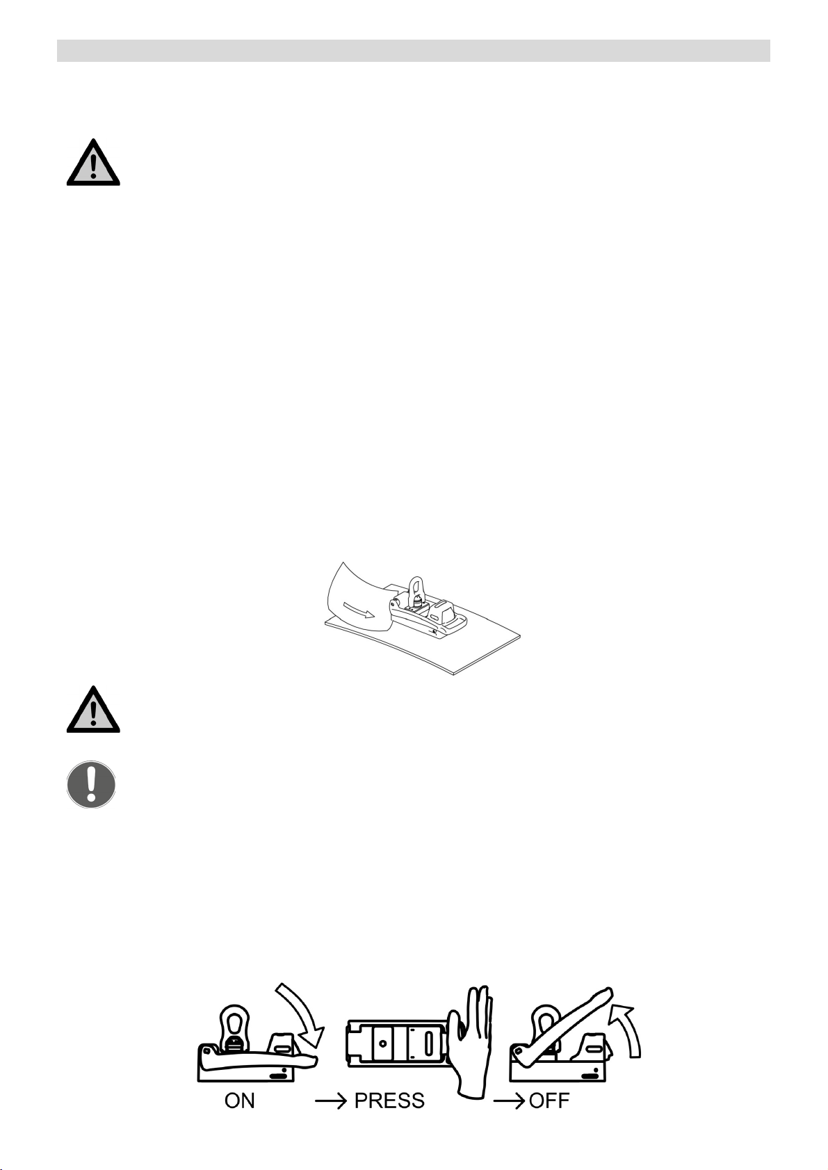
•den Lasthebemagneten vollständig aktivieren
•den Lasthebemagneten auf metallischen, ferromagnetischen Materialien aktivieren
•Lasten senkrecht heben
•die gesamte Magnetfläche beim Heben nutzen
•auf planen Oberflächen heben
•die magnetische Haltekraft prüfen, indem die Last um etwa 10 cm angehoben wird
•die Magnetfläche reinigen und von Schmutz, Spänen und Schweißkörnern befreien
•den Lasthebemagneten sanft absetzen, um die Magnethaftfläche nicht zu beschädigen
•den Gefahrenbereich beim Heben der Last überprüfen
•den gesamten Lasthebemagneten und insb. die Magnetfläche auf Beschädigung prüfen
•die passenden Hebezeuge verwenden
•die Anweisungen dieser Bedienungsanleitung befolgen
•neue Nutzer in den sicheren Gebrauch von Lasthebemagneten einweisen
•die lokalen, landesspezifischen Richtlinien befolgen
•in einer trockenen Umgebung lagern und verwenden
Niemals…
•runde oder gewölbte Objekte heben
•eine seitliche Belastung der Ringschraube zulassen
•über der angegebenen Maximallast heben
•Lasten über Personen hinweg transportieren
•mehrere Werkstücke gleichzeitig anheben
•den Lasthebemagneten deaktivieren, bevor die Last sicher abgesetzt ist
•Lasten zum Schwingen bringen oder abrupt anhalten
•Lasten außerhalb der empfohlenen Größen heben
•Lasten mit Hohlräumen, Ausschnitten oder Bohrungen heben
•ungleichmäßige Lasten heben
•Veränderungen am Lasthebemagneten vornehmen oder Hinweisschilder entfernen
•den Lasthebemagneten bei Beschädigung oder bei fehlenden Teilen verwenden
•die Magnetunterseite starken Stößen oder Schlägen aussetzen
•unter der gehobenen Last aufhalten
•Lasten anheben, so lange sich Personen im Gefahrenbereich aufhalten
•die gehobene Last unbeaufsichtigt lassen
•den Lasthebemagneten ohne fachgerechte Einweisung verwenden
•benutzen, sofern diese Bedienungsanleitung nicht vollständig gelesen und verstanden wurde
•den Lasthebemagneten zum Unterstützen, Heben oder Transportieren von Personen nutzen
•den Lasthebemagneten bei Temperaturen über 60°C (140°F) betreiben
•mit ätzenden Stoffen in Verbindung bringen
Personen mit Herzschrittmacher oder anderen medizinischen Apparaten dürfen den
Lasthebemagneten nur nach vorheriger Zustimmung eines Arztes benutzen!

4
Bestimmungsgemäße Verwendung
Der Permanent-Lasthebemagnet TML 500 F ist für das Heben von ferromagnetischen, metallischen Lasten
bestimmt. Er darf ausschließlich in Verbindung mit Lasttraversen und im Rahmen seiner technischen Daten und
Bestimmung verwendet werden.
Die bestimmungsgemäße Verwendung umfasst die Einhaltung aller vom Hersteller angegebenen Inbetriebnahme-,
Betriebs-, Umgebungs- und Wartungsbedingungen. Ausschließlich der Nutzer ist für das Verstehen der
Bedienungsanleitung sowie für die sachgerechte Anwendung, Wartung und Pflege des Lasthebemagneten
verantwortlich.
Gerätebeschreibung
Der TML (Thin Material Lifter) ist ein dauermagnetischer Lasthebemagnet mit manueller Betätigung für das Heben,
Transportieren und Senken von ferromagnetischen Materialien.
Über ein Herunterdrücken des Hebels (F) kann das vom Permanentmagneten erzeugte Magnetfeld im Bereich der
Magnetunterplatte (C) aktiviert werden. Auf Grund der besonderen Konstruktion entsteht ein sehr kompaktes
Magnetfeld, welches insbesondere auf dünnen Materialien unter 10 mm eine sehr gute Haftkraft entwickelt. Für eine
Deaktivierung des Magneten muss die Sicherheitslasche (E) mit dem Handballen hineingedrückt werden und der
Hebel kann nach oben bewegt werden.
Unterhalb der Sicherheitslasche befindet sich ein variabel einstellbarer Öl-Dämpfer (G), der insbesondere auf
dünnen Materialien die Rückstellenergie des Hebels absorbieren kann. Zusätzliche Montagegewinde an den beiden
Stirnseiten des Magneten ermöglichen eine individuelle Nutzung als Haltevorrichtung.
An der Oberseite des Lasthebemagneten befindet sich eine Ringschraube (A) zur Befestigung an einer Lasttraverse.
Die Tragfähigkeit des Lasthebemagneten entspricht 1/3 der maximalen Abrisskraft des Magneten und entspricht
somit dem gängigen Sicherheitsfaktor von 3:1.
A) Ringschraube
B) Grundkörper
C) Magnethaftfläche
D) Magnetisches Zentrum des Magneten
E) Sicherheitslasche
F) Hebel für Aktivierung / Deaktivierung
G) Dämpfer für Hebel
H) Zusätzliche Montagegewinde

5
Technische Daten
Art.-Nr.:
41500.F
Bezeichnung:
TML 500 F Lasthebemagnet
mit fester Ringschraube
Abrisskraft:
>1500 kg ab 15 mm S235
>3300 lbs ab ½” AISI CRS 1020
Max. Tragfähigkeit:
(auf Flachmaterial bei 0° Neigung der
Last und 3:1 Sicherheitsfaktor)
500 kg ab 15 mm S235
1100 lbs ab ½” AISI CRS 1020
Eigengewicht des Magneten:
7,3 kg
16 lbs
Lagertemperatur:
-30°C bis +60°C
-22°F bis +140°F
Betriebstemperatur:
-10°C bis +60°C
+14°F bis +140°F
Kennzeichnung des Lasthebemagneten
Auf beiden Seiten des Lasthebemagneten befinden sich zusätzliche detaillierte Beschreibungen für die Handhabung
und die Einsatzbedingungen. Diese Beschriftung darf nicht modifiziert, beschädigt oder entfernt werden, da
andernfalls der Hersteller von der Haftung für mögliche Personenschäden, Sachschäden oder Unfälle, die sich aus
diesem Umstand ergeben, entbunden wird. Gegebenenfalls müssen neuen Etiketten beim Hersteller nachbestellt
werden.

6
Inbetriebnahme
Sie erhalten einen vollständig montierten Lasthebemagneten mit einer detaillierten Bedienungsanleitung. Bitte prüfen
Sie bei Erhalt der Ware deren Zustand auf mögliche Transportschäden und den Lieferumfang auf Vollständigkeit.
Wenden Sie sich bei Problemen bitte umgehend Ihren Händler oder den Hersteller.
Vor dem ersten Gebrauch unbedingt die gesamte Bedienungsanleitung lesen!
1. Befolgen Sie alle genannten Sicherheitshinweise. Reinigen Sie das Werkstück und die Magnethaftfläche des
Lasthebemagneten.
Hinweis:
Obwohl der Aktivierungshebel des TML-Magneten nach oben gerichtet ist (Position OFF), verfügt der
Magnet über eine leichte magnetische Vorspannung. Diese erleichtert Ihnen nicht nur die Positionierung
des TML 500 F auf dem Werkstück, sondern verhindert auch ein unbeabsichtigtes Verrutschen oder
Abfallen des Magneten oder des Werkstücks.
2. Platzieren Sie den Lasthebemagneten im Schwerpunkt der Last.
3. Richten Sie den Lasthebemagneten nun je nach Wunsch und Anwendung aus. Dabei ist stets auf eine
senkrechte Belastungsrichtung der Ringschraube zu achten.
4. Drücken Sie den Aktivierungshebel bis zum Anschlag nach unten (Position ON). Achten Sie darauf, dass er
vollständig unterhalb der Sicherheitslasche einrastet.
5. Testen Sie die Magnethaftkraft: Bringen Sie den Lasthaken in die gewünschte Position und heben Sie die Last
etwa 10 cm an, um die Haftkraft des TML-Magneten und eine mögliche Verformung der Last zu prüfen.
6. Prüfen Sie, ob sich an den Rändern der Magnethaftfläche ein kleiner Abstand (Luftspalt) zwischen Magnet und
Werkstück bildet. Dies können Sie z.B. mit einem Blatt Papier (80 g/m2) tun. Bei einem Luftspalt wird die
Tragfähigkeit des Lasthebemagneten erheblich reduziert.
7. Bei ausreichender Haftkraft und keiner übermäßigen Verformung der Last, können Sie den Hebevorgang
fortsetzen.
8. Bewegen Sie Ihre Last stets langsam und gleichmäßig. Vermeiden Sie Schwingungen, Stöße oder eine
seitliche Belastung der Ringschraube.
9. Nachdem die Last vollständig und in einen sicheren Stand abgesetzt wurde, können Sie den Lasthebe-magneten
deaktivieren. Drücken Sie hierfür die Sicherheitslasche mit der Seite Ihrer Hand nach innen und bewegen Sie
den Hebel nach oben in die Position OFF.
Stoppen Sie bei übermäßiger Verformung des Werkstücks oder einem Luftspalt sofort den
Hebevorgang.
Nutzen Sie Lasttraversen mit zusätzlichen Lasthebemagneten, um biegsame oder besonders
große Lasten zu heben.

7
Variabler Dämpfer
Auf der Rückseite des Magneten unter der Sicherheitslasche befindet sich ein Öl-Dämpfer, der die Rückstell-energie
des Hebels absorbieren kann. Je dünner das zu hebende Material ist, umso mehr Rückstellenergie muss absorbiert
werden. Die Stellschraube auf der Rückseite des Magneten ermöglicht ein variables Einstellen des Dämpfers,
sodass der Hebel entweder sehr leicht oder stark gebremst nach oben zu bewegen geht. Die Einstellung erfolgt mit
einem Schlitzschraubendreher.
Grundlegende Informationen über die Tragfähigkeit des Lasthebemagneten
Auf der Unterseite des Lasthebemagneten befindet sich die Magnethaftfläche mit den unterschiedlichen
magnetischen Polen, welche im aktivierten Zustand über den Magnetfluss die Haftkraft erzeugen. Die maximal
erreichbare Haftkraft hängt von verschiedenen Faktoren ab, die im Folgenden erläutert werden:
Materialstärke
Der Magnetfluss des Lasthebemagneten benötigt eine Mindestmaterialstärke, um die Last vollständig zu durchfluten.
Ist diese Materialstärke nicht gegeben, reduziert sich die maximale Haftkraft in Abhängigkeit von der Materialstärke.
Herkömmliche schaltbare Permanentmagnete haben ein sehr tief reichendes Magnetfeld, ähnlich der Pfahlwurzel
eines Baumes, und benötigen für das Erreichen der maximalen Haftkraft eine hohe Materialstärke. Das kompakte
Magnetfeld der TML Magnete ist ähnlich einer Flachwurzel und erreicht schon bei geringen Materialstärken die
maximale Haftkraft (siehe Tabelle 2 im Kapitel „Detaillierte Leistungsdaten“).
Werkstoff
Jeder Werkstoff reagiert unterschiedlich auf die Durchdringung der Magnetfeldlinien. Die Tragfähigkeit der
Lasthebemagnete wird auf einem S235 Material ermittelt. Stähle mit einem hohen Kohlenstoffanteil oder einer durch
Wärmebehandlung geänderten Struktur haben eine geringe Haftkraft. Auch geschäumte oder porenbehaftete
Gussbauteile haben eine geringere Haftkraft, sodass die angegebene Tragfähigkeit des Lasthebemagneten anhand
der folgenden Tabelle 1 abgewertet werden kann.
Tabelle 1
Material
Magnetkraft in %
Unlegierter Stahl (0,1-0,3% C - Gehalt)
100
Unlegierter Stahl (0,3-0,5% C - Gehalt)
90-95
Stahlguss
90
Grauguss
45
Nickel
11
Edelstahl, Aluminium, Messing
0
Oberflächenbeschaffenheit
Die maximale Haftkraft eines Lasthebemagneten ergibt sich bei einem geschlossenen Magnetkreis, in dem sich die
Magnetfeldlinien ungehindert zwischen den Polen verbinden können und so ein hoher magnetischer Fluss entsteht.
Im Gegensatz zu Eisen ist z.B. Luft ein sehr großer Widerstand für den magnetischen Fluss. Entsteht eine Art
„Luftspalt“ zwischen dem Lasthebemagneten und dem Werkstück, verringert dies die Haftkraft. So bilden z.B. auch
Farbe, Rost, Zunder, Oberflächenbeschichtungen, Fett oder ähnliche Stoffe einen Abstand, also einen Luftspalt,
zwischen Werkstück und dem Hebemagneten. Auch eine zunehmende Oberflächenrauheit oder Unebenheit der
Oberfläche beeinflusst die Haftkraft negativ. Richtwerte hierzu finden Sie in der Leistungstabelle Ihres
Lasthebemagneten.

8
Abmessungen der Last
Beim Arbeiten mit großen Werkstücken wie z.B. Trägern oder Platten kann sich die Last beim Hebevorgang teilweise
verformen. Eine große Stahlplatte würde sich an den Außenkannten nach unten biegen und so in Summe eine
gewölbte Oberfläche erzeugen, die nicht mehr vollständig von der Magnetunterseite kontaktiert wird. Der
entstehende Luftspalt reduziert die maximale Tragfähigkeit des Lasthebemagneten. Im Gegensatz dazu sollten die
Objekte auch nicht hohl oder kleiner sein als die Magnethaftfläche, da sonst nicht die gesamte Leistungsfähigkeit
des Lasthebemagneten genutzt wird.
Ausrichtung der Last
Beim Transport der Last ist darauf zu achten, dass sich der Lasthebemagnet im Schwerpunkt des Werkstücks
befindet und die Last bzw. der Lasthebemagnet immer horizontal ausgerichtet ist. In dieser Belastungssituation wirkt
die Magnetkraft am Lasthebemagneten mit seiner vollen Abrisskraft normal zur Oberfläche und es ergibt sich über
den 3:1 Sicherheitsfaktor die maximal angegebene Tragfähigkeit.
Temperatur
Die in dem Lasthebemagneten verbauten Hochleistungspermanentmagnete verlieren ab einer Temperatur von mehr
als 80°C (180°F) irreversibel ihre magnetischen Eigenschaften, sodass anschließend selbst bei abgekühltem
Magneten die volle Tragfähigkeit nie wieder erreicht wird. Bitte beachten Sie die Angaben an ihrem Produkt und in
der Bedienungsanleitung.
Wartung und Inspektion
Der Nutzer hat die Pflicht, den Lasthebemagneten gemäß der Angaben in der Bedienungsanleitung und
entsprechend der landesspezifischen Normen und Regeln (z.B. ASME B30.20B, DGUV-Information 209-013;
AMVO) zu warten und zu pflegen.
Die Wartungsintervalle werden nach der empfohlenen, durchzuführenden Häufigkeit eingeteilt:
Vor jeder Benutzung…
•den Lasthebemagneten visuell auf Beschädigung prüfen
•die Werkstückoberfläche und die Magnetunterfläche reinigen
•die Magnetunterfläche von Rost, Spänen oder Unebenheiten befreien
Wöchentlich…
•den Lasthebemagneten auf Verformung, Risse oder andere Defekte kontrollieren
•die korrekte Funktion und das Einrasten des Aktivierungshebels überprüfen
•die Ringschraube auf Beschädigung, Verformung, Risse oder Verschleiß prüfen und ggf. ersetzen lassen
•die Magnetunterfläche auf Kratzer, Druckstellen oder Risse prüfen, den Magneten wenn nötig beim
Hersteller reparieren lassen
Monatlich…
•die Markierungen und die Beschriftung des Lasthebemagneten auf Lesbarkeit und Beschädigung prüfen
und bei Bedarf ersetzen
Jährlich…
•die Tragfähigkeit des Lasthebemagneten vom Hersteller oder einer autorisierten Werkstatt prüfen lassen
Eigenständige Reparaturen oder Modifikationen am Lasthebemagneten sind nicht erlaubt.
Bei Fragen oder Unklarheiten wenden Sie sich an den Hersteller!
Die jährliche Prüfung für die 3-fache Sicherheit dieses Hebemagneten ist empfehlenswert. Gerne übernehmen
wir diese Prüfung aus erster Hand für Sie. Bei Interesse senden Sie uns bitte eine E-Mail an:
TML-Test@alfra.de
Sie erhalten dann umgehend ein Angebot und haben die Sicherheit, dass Ihr Alfra-Hebemagnet prozesssicher
geprüft wird – und zwar dort, wo er auch produziert wird.

9
Detaillierte Leistungsdaten des TML 500 F
Die Werte für die Tragfähigkeit des TML 500 F basieren auf dem Material S235 JR für die maximale, senkrechte
Abzugskraft mit 0° Abweichung zur Lastachse und einem Sicherheitsfaktor von 3:1. Es erfolgen keine Angaben zu
Rundmaterial, da der TML 500 F für Flachmaterial optimiert ist und Rundmaterial oder gewölbte Objekte nicht
gehoben werden dürfen.
Tabelle 2
Tragfähigkeit in kg
Materialstärke
Sauber, flach
geschliffene
Oberfläche
Rostige, leicht
zerkratzte
Oberfläche
Unregelmäßige,
rostige oder raue
Oberfläche
Luftspalt <0,1 mm
Luftspalt =0,25 mm
Luftspalt =0,5 mm
mm
0°
0°
0°
2
50
45
40
3
130
115
85
4
195
160
135
5
300
240
190
6
360
270
220
8
455
310
240
10
490
360
245
15
500
365
250
>20
500
370
250
Tragfähigkeit in lbs
Materialstärke
Sauber, flach
geschliffene
Oberfläche
Rostige, leicht
zerkratzte
Oberfläche
Unregelmäßige,
rostige oder raue
Oberfläche
Luftspalt <0,004 inch
Luftspalt =0,01 inch
Luftspalt =0,02 inch
inch
0°
0°
0°
0,08
110
100
90
0,12
285
255
185
0,16
430
355
295
0,20
660
525
415
0,25
800
595
480
0,30
1000
685
525
0,40
1090
785
540
0,50
1100
800
545
>1
1100
815
555
Die maximalen Abmessungen der zu hebenden Lasten hängen von der Geometrie und Biegesteifigkeit der
Werkstücke ab. Bei übermäßiger Durchbiegung des Materials bildet sich ein Luftspalt unterhalb der Magnetfläche,
der Tragfähigkeit des Magneten erheblich reduziert.
Achten Sie bei jedem Hebevorgang auf eine Verformung des Werkstücks und überprüfen Sie die Entstehung eines
Luftspaltes an den Rändern der Magnethaftfläche, z.B. mit einem Blatt Papier (80g/m2) prüfen. Um biegsame oder
besonders große Lasten zu heben, sollten Lasttraversen mit zusätzlichen Lasthebemagneten genutzt werden.
Stoppen Sie den Hebevorgang bei übermäßiger Verformung des Werkstücks oder einem
Luftspalt sofort.
Überschreiten Sie niemals die in Tabelle 2 angegebenen Lastwerte.

10
Markus A. Döring
(Geschäftsführer)
EG-Konformitätserklärung im Sinne der Maschinenrichtlinie 2006/42/EG
Hiermit erklären wir,
Alfra GmbH
2. Industriestr. 10
68766 Hockenheim
dass der schaltbare Permanentmagnet-Lasthebemagnet
TML 500 F
ab Seriennummer 16G1515
den folgenden Normen entspricht:
EN ISO 12100:2010
EN 13155:2003+A2:2009
Bei einer nicht mit dem Hersteller abgesprochenen Änderung des Produktes verliert diese Erklärung ihre Gültigkeit.
Weiterhin verliert diese Erklärung ihre Gültigkeit, wenn das Produkt nicht entsprechend den in den
Benutzerinformationen aufgezeigten bestimmungsgemäßen Anwendungsfällen eingesetzt wird oder die regelmäßig
durchzuführenden Wartungen gemäß dieser Anleitung oder den landesspezifischen Vorschriften nicht eingehalten
werden.
Bevollmächtigt für die Zusammenstellung der Unterlagen:
Alfra GmbH
2. Industriestr. 10
68766 Hockenheim
Hockenheim, 20.07.2017

11
Dear customer,
Thank you for purchasing an ALFRA product. Read these operation instructions closely before using your device for
the first time and keep them along with the enclosed Product Control Card for later reference.
Safety Instructions
Dangers can occur when transporting loads by lifting devices due to improper handling and/or poor maintenance,
which may cause serious accidents with fatal physical injuries. Read these operation instructions closely and observe
all safety instructions mentioned therein. Contact the manufacturer if you have any questions.
Always...
•activate the lifting magnet completely
•activate the lifting magnet on metallic, ferromagnetic materials
•lift loads vertically
•use the entire magnetic surface for lifting
•lift on plane surfaces
•check the magnetic holding force by lifting the load slightly by about 10 cm
•clean the magnetic surface and keep it clear of dirt, chips and welding spatter
•set the lifting magnet down gently to prevent damage to the magnetic surface
•check the hazard area when lifting the load
•inspect the magnetic surface and the entire lifting magnet for damage
•use suitable lifting gear
•follow the instructions in these operating instructions
•instruct new operators to the safe use of lifting magnets
•respect local, country-specific guidelines
•store in a dry place
Never...
•lift round or arched objects
•allow for a lateral load of the lifting eyebolt
•exceed the stated maximum load
•lift loads over people
•lift more than one work piece at a time
•switch the lifting magnet off before setting down the load safely
•allow the load to sway or bring to a sharp and immediate stop
•lift loads exceeding the recommended dimensions
•lift loads with cavities, cut-out openings or drilled holes
•lift unbalanced loads
•modify the lifting magnet or remove operating labels
•use the lifting magnet if damaged or missing parts
•strain the underside of the magnet through heavy impact or blows
•position yourself beneath the lifted load
•lift loads while people are within the hazard area
•leave the load hanging unattended
•use the lifting magnet without having been properly instructed
•use if you have not read and understood these operating instructions completely
•use the lifting magnet to support, lift or transport persons
•operate the lifting magnet in temperatures higher than 60°C (140°F)
•expose to corrosive substances
People using pacemakers or other medical devices should not use this lifting magnet until
they have consulted with their physician.

12
Proper Use
The permanent lifting magnet TML 500 F has been designed for lifting ferromagnetic, metallic loads. It may only be
used in combination with spreader bars and within the context of its technical data and purpose.
Proper use also includes adherence to the start-up, operating, environment and maintenance conditions specified
by the manufacturer. Any use going beyond this is considered improper, and the manufacturer will not be liable for
any damage resulting from such use.
Device Description
The TML (Thin Material Lifter) is a switchable lifting magnet with manual actuation for the lifting, transporting and
lowering of ferromagnetic materials.
By pressing the lever (F) down, the magnetic field generated by the permanent magnet can be activated in the lower
magnetic plate (C) area. Thanks to the special design, a very compact magnetic field is generated which develops
excellent adhesive force, especially on thin materials (less than 10 mm). The magnet can be deactivated by first
pressing the safety tab (E) with the heel of the hand and then moving the lever upwards. An adjustable oil damper is
incorporated underneath the safety tab in order to absorb the recoil energy of the lever, especially during use on thin
materials. Additional threads for mounting are located on either front side of the magnet which, if desired, can be
used as holding device. A lifting eye bolt (A) is situated on the top of the lifting magnet for attachment to spreader
bars. The load-bearing capacity of the lifting magnet is equivalent to 1/3 of the maximum breakaway force of the
magnet and thus is equivalent to the standard safety factor 3:1.
A) Lifting eye bolt
B) Basic body
C) Magnetic contact area
D) Center of the magnet
E) Safety tab
F) Lever for activation/deactivation
G) Shock absorber for lever
H) Additional threads for mounting

13
Technical Data
Prod.-No.:
41500.F
Designation:
TML 500 F Lifting magnet
with fixed eye bolt
Breakaway force:
>1500 kg from 15 mm S235
>3300 lbs from ½”
AISI CRS 1020
Max. load-bearing capacity:
(on flat material at 0° inclination
of the load, with safety factor 3:1)
500 kg from 15 mm S235
1100 from ½” AISI CRS 1020
Dead weight of the magnet:
7.3 kg
16 lbs
Storage temperature:
-30°C to +60°C
-22°F to +140°F
Operating temperature:
-10°C to +60°C
+14°F to +140°F
Markings on the Lifting Magnet
Additional detailed descriptions for handling and operating conditions can be found on both sides of the lifting magnet.
This labeling must not be modified, damaged or removed, as otherwise the manufacturer cannot be held responsible
for any personal injuries, property damage or accidents resulting from this fact. New labels must be ordered from the
manufacturer if necessary.

14
Start-up
You have received a completely assembled lifting magnet and detailed operating manual. Please check the condition
of the goods upon receipt for any damage incurred during transport, and make sure the delivery is complete. If you
have any problems, please contact the authorized reseller or manufacturer immediately.
Be sure to read the operation instructions completely before using this magnet for the first
time!
1. Follow the safety instructions. Clean the work piece and the magnetic contact area of the lifting magnet.
Note: Although the activation lever of the TML-Magnet is facing upwards (OFF position), the magnet
still has a slight magnetic pre-tensioning. This pre-tension does not only allow for ease of positioning
the TML 500 F to the workpiece, it also avoids inadvertent slippage or dropping of the lifting magnet
or the workpiece.
2. Position the lifting magnet at the center of gravity of the load.
3. Align the lifting magnet according to the desired application. Always ensure a vertical load direction of the
eyebolt.
4. Press the activation lever down until it is fully engaged in the ON position. Make sure that it is securely
locked underneath the safety tab.
5. Perform a test lift: Move the load hook to the required position and lift the load by about 10 mm to check its
deformation and the magnetic holding force of the TML-Magnet.
6. Check for any air gap developing at the edges of the magnetic surface contact area, for instance by means
of a sheet of paper (80g/m2). If a small distance (air gap) forms between magnet and workpiece, the load-
bearing capacity of the lifting magnet will be reduced significantly.
Immediately stop the lift if there is any excessive deformation of the workpiece or an air gap.
7. If the magnetic adhesion is sufficient and there is no deformation, you can continue the lift.
8. Be sure to move your load slowly and smoothly. Avoid swinging, jarring or any lateral load of the eyebolt.
9. After the load has been set down completely and safely, you can deactivate the lifting magnet. To do this,
press the safety tab using the heel of your hand and move the lever upwards into the OFF position.
Use spreader bars with additional magnets to safely lift large or flexible loads.

15
Adjustable Shock Absorber
An oil filled shock absorber is incorporated on the backside of the magnet in order to absorb any recoil energy of the
lever. The thinner the material to be lifted the higher the recoil energy to be absorbed. The set screw on the backside
of the magnet makes it possible to adjust the shock absorber variably, so that the upward movement of the lever is
controlled and operates smoothly. This adjustment should be made by using a flat-blade screwdriver.
Basic Information on the Load-bearing Capacity of the Lifting Magnet
The magnetic surface is located on the underside of the lifting magnet incorporating multiple magnetic poles which
generate the magnetic holding force when activated. The maximum holding force that can be achieved depends on
different factors which are explained below:
Material thickness
The magnetic flux of the lifting magnet requires a minimum material thickness to flow completely into the load. Below
this minimum thickness of material, the maximum holding force is reduced subject to material thickness. Conventional
switchable permanent magnets have a deep penetrating magnetic field similar to tree tap roots, and require a large
material thickness to achieve maximum holding force. The compact magnetic field of the TML magnets is similar to
a shallow root and achieves maximum holding force even when used on thin materials (see table 2, chapter “Detailed
Performace Data“).
Material
Every material reacts in a different way to penetration of the magnetic field lines. The load-bearing capacity of the
lifting magnets is determined using a low carbon material. Steels with high carbon content or whose structure has
been changed by heat treatment have a lower holding force. Foamed or porous cast components also have a lower
holding force, so that the given load-bearing capacity of the lifting magnet can be downgraded on the basis of the
following table1.
Table 1
Material
Magnetic force in %
Non-alloyed steel (0.1-0.3% C content)
100
Non-alloyed steel (0.3-0.5% C content)
90-95
Cast steel
90
Grey castiron
45
Nickel
11
Most stainless steels, aluminium, brass
0
Surface quality
The maximum holding force of a lifting magnet can be achieved in case of a closed magnetic circuit in which the
magnetic field lines can connect up freely between the poles, thus creating a high magnetic flux. In contrast to iron,
for example, air has very high resistance to magnetic flux. If a kind of “air gap” is formed between the lifting magnet
and the work piece, the holding force will be reduced. In the same way, paint, rust, scale, surface coatings, grease
or similar substances all constitute a space, or an air gap, between work piece and lifting magnet. An increase in
surface roughness or unevenness also has an adverse effect on the magnetic holding force. Reference values can
be found in the performance table of your lifting magnet.

16
Load dimensions
When working with large workpieces such as girders or plates, the load can deform during the lift. A large steel plate
would bend downwards at the outer edges and create a curved surface which no longer has full contact with the
bottom of the magnet. The resulting air gap reduces the maximum load-bearing capacity of the lifting magnet. Hollow
objects or those smaller than the magnetic surface will also result in less holding power being available.
Load alignment
During load transport, care must be taken that the lifting magnet is always at the center of gravity of the work piece
and that load, or lifting magnet respectively, is always aligned horizontally. In this case, the magnetic force of the
lifter acts with its breakaway force perpendicular in relation to the surface, and the maximum rated load-bearing
capacity is achieved with the 3:1 standard safety factor.
Temperature
The high-power permanent magnets installed in the lifting magnet will begin to lose their magnetic properties
irreversibly from a temperature of more than 80°C (180°F), so that the full load-bearing capacity is never reached
again even after the magnet has cooled down. Please note the specifications on your product or in the operating
manual.
Maintenance and Inspection
The user is obliged to maintain and service the lifting magnet in compliance with the specifications in the operating
manual and according to the country-specific standards and regulations (e.g. ASME B30.20B, DGUV-Information
209-013; AMVO).
The maintenance intervals are classified according to the recommended schedule.
Before every use...
•visually inspect the lifting magnet for damage
•clean the surface of the workpiece and the underside of the magnet
•free the underside of the magnet of rust, chips or unevenness
Weekly...
•inspect the lifting magnet for deformation, cracks or other defects
•make sure the activation lever is working properly and latches correctly into place
•inspect the lifting eyebolt for damage, deformation, cracks or wear and have it replaced if necessary
•inspect the bottom of the magnet for scratches, pressure points or cracks and have the magnet repaired by
the manufacturer if necessary
Monthly...
•check the markings and labelling on the lifting magnet for legibility and damage and replace them if
necessary
Annually...
•have the load-bearing capacity of the lifting magnet checked by the supplier or an authorised workshop
Unauthorized repairs or modification to the lifting magnet are not permitted.
If you have any questions contact the manufacturer.
An annual inspection is recommended for the safe use of this lifting magnet. We will be glad to perform this
inspection for you in-house. Please send us an email to:
You will then promptly receive an offer and have the assurance that the lifting magnet will be inspected in a
process-reliable manner where it was actually produced.

17
Detailed Performance Data for the TML 500 F
Values shown for load capacity of the TML 500 F are based on material S235 JR for the maximum, vertical tractive
force with 0° deviation from the load axis including a 3:1 safety factor. This manual does not contain any instructions
for use on round material, as the TML 500 F is designed for flat material and round material or arched objects may
not be lifted.
Table 2
Load capacity in kg
Thickness of
material
Clean, flat, ground
surface
Rusty, slightly scratched
surface
Irregular, rusty or rough
surface
Air gap <0.1 mm
Air gap = 0.25 mm
Air gap = 0.5 mm
mm
0°
0°
0°
2
50
45
40
3
130
115
85
4
195
160
135
5
300
240
190
6
360
270
220
8
455
310
240
10
490
360
245
15
500
365
250
>20
500
370
250
Load capacity in lbs
Thickness of
material
Clean, flat, ground
surface
Rusty, slightly scratched
surface
Irregular, rusty or rough
surface
Air gap <0.004 inches
Air gap = 0.01 inches
Air gap = 0.02 inches
inch
0°
0°
0°
0,08
110
100
90
0,12
285
255
185
0,16
430
355
295
0,20
660
525
415
0,25
800
595
480
0,30
1000
685
525
0,40
1090
785
540
0,50
1100
800
545
>1
1100
815
555
The maximum dimensions of the loads to be lifted depend to a large extent on the geometry and flexural stiffness of
the work pieces. If the material bends, an air gap will form under the magnetic surface which will decrease the load-
bearing capacity significantly.
During each lift, watch for any deformation of the work piece that might occur and check for any air gap developing
at the edges of the magnetic surface contact area. You can use for instance a sheet of paper (80g/m2) to check this.
Spreader bars with additional magnets may be required to safely lift large or flexible loads.
Immediately stop the lift if there is any excessive deformation of the work piece or an air gap.
Never exceed load-bearing capacity given in the table 2.

18
Markus A. Döring
(Managing Director)
EC Declaration of conformity as defined by the Machinery Directive 2006/42/EC
We,
Alfra GmbH
2. Industriestr. 10
68766 Hockenheim/Germany
hereby declare that the switchable permanent magnet-type lifting magnet
TML 500 F
from serial number 16G1515 onwards
complies with the following standards:
EN ISO 12100:2010
EN 13155:2003+A2:2009
This certificate is no longer valid if the product is modified without the manufacturer's consent. Furthermore, this
certificate is no longer valid if the product is not used properly in accordance with the use cases documented in the
user manual or if regular maintenance is not carried out in accordance with this manual or country-specific
regulations.
Person authorised to compile the documents:
Alfra GmbH
2. Industriestr. 10
68766 Hockenheim/Germany
Hockenheim/Germany, 20.07.2017

19
Cher client,
ALFRA vous remercie d’avoir choisi ce produit. Veuillez lire le présent manuel d’utilisation attentivement avant la
première utilisation de votre machine et gardez-le avec la carte de produit jointe (Product Control Card) pour vous y
référer ultérieurement.
Consignes de sécurité
Lors du transport de charges, des dangers considérables peuvent apparaître en cas d’utilisation non conforme et/ou
de mauvaise maintenance des engins de levage, qui peuvent entraîner de graves accidents avec des blessures
potentiellement mortelles. Veuillez lire le présent manuel d’utilisation attentivement et suivre toutes les consignes de
sécurité qui y sont mentionnées. Contactez le fabricant en cas de questions.
Toujours…
•activer complètement l’aimant de levage
•activer l’aimant de levage sur les matériaux métalliques et ferromagnétiques
•utiliser toute la surface magnétique lors du levage
•soulever des charges verticalement
•soulever sur des surfaces plates
•contrôler la force de maintien magnétique en levant la charge sur environ 10 cm
•nettoyer la surface magnétique et éliminer la poussière, la limaille et les résidus de soudure
•décrocher l’aimant de levage en douceur afin d’éviter d’endommager la surface de
maintien magnétique
•vérifier la zone de danger lors du levage de la charge
•vérifier que la surface magnétique et l’ensemble de l’aimant de levage ne présentent pas
de dommages
•utiliser des engins de levage adaptés
•respecter les instructions du manuel d’utilisation
•initier les nouveaux utilisateurs à l’utilisation sûre des aimants de levage
•respecter les directives locales spécifiques au pays
•stocker dans un endroit sec
Ne jamais…
•soulever des objets ronds ou bombés
•permettre une charge latérale de l’anneau à tige
•soulever en dépassant la charge maximale indiquée
•transporter des charges au-dessus de personnes
•soulever plusieurs pièces à la fois
•désactiver l’aimant de levage avant d’avoir posé la charge en toute sécurité
•faire osciller les charges ou les arrêter brusquement
•soulever des charges dont les dimensions dépassent les valeurs maximales recommandées
•soulever des charges avec des creux, des fissures ou des trous
•soulever des charges inégalement réparties
•modifier l’aimant de levage ou retirer les panneaux d’avertissement
•utiliser l’aimant de levage en cas de dommages ou de pièces manquantes
•donner des coups ou des chocs violents sur le côté inférieur de l’aimant
•stationner sous des charges suspendues
•soulever des charges si des personnes se trouvent dans la zone de danger
•laisser une charge suspendue sans surveillance
•utiliser l’aimant de levage sans avoir reçu les instructions appropriées
•utiliser sans avoir entièrement lu et compris ce manuel d’utilisation
•utiliser l’aimant de levage pour soutenir, lever ou transporter des personnes
•faire fonctionner l’aimant de levage à des températures supérieures à 60 °C (140 °F)
•poser à proximité de substances corrosives
Les personnes porteuses d’un stimulateur cardiaque ou de tout autre appareil médical ne
peuvent utiliser l’aimant de levage qu’avec l’accord préalable d’un médecin !

20
Utilisation conforme à l’usage prévu
L’aimant de levage TML 500 F permanent est conçu pour soulever des charges ferromagnétiques métalliques. Il doit
être utilisé exclusivement en combinaison avec des traverses de charge et dans le cadre de ses données techniques
et de son usage.
Une utilisation conforme inclut également le respect des conditions de mise en service, d’utilisation, de maintenance
et d’environnement indiquées par le fabricant. Uniquement l'utilisateur est responsable pour l'utili-sation, la
maintenance et de l'entretien correcte ainsi que de la compréhension du mode d’emploi de l’aimant de levage.
Description de l’appareil
L’aimant TML (Thin Material Lifter) est un aimant de levage magnétique permanent avec activation manuelle pour le
levage, le transport et l’abaissement de matériaux ferromagnétiques.
En abaissant le levier (F), le champ magnétique généré par l’aimant permanent peut être activé dans la zone de la
plaque inférieure magnétique (C). En raison de la construction particulière, un champ magnétique très compact est
formé, qui permet une excellente force de maintien en particulier sur les matériaux fins de moins de 10 mm. Pour
désactiver l’aimant, la languette de sécurité (E) doit être pressée avec la paume de la main, le levier peut alors être
déplacé vers le haut.
Un amortisseur à l’huile (G), qui peut être réglé en continu, est situé au-dessous de la languette de sécurité afin
d’absorber l’énergie de recul du levier, en particulier sur les matériaux fins. Des filetages de montage
supplémentaires (H) se trouvent sur chaque côté de la face frontale de l’aimant qui peuvent être utilisés, selon
l’application, en tant que dispositif de retenue. Un anneau à tige (A) est situé sur le côté supérieur de l’aimant de
levage pour la fixation sur une traverse de charge. La capacité de charge de l’aimant de levage correspond à 1/3 de
la force d'arrachement maximal de l’aimant et correspond au coefficient de sécurité standard de 3:1.
A) Anneau à tige
B) Structure de base
C) Surface de maintien magnétique
D) Centre magnétique de l’aimant
E) Languette de sécurité
F) Levier pour l’activation/la désactivation
G) Amortisseur pour le levier
H) Filetages de montage supplémentaires
Table of contents
Languages:
Other ALFRA Lifting System manuals