8
ontage- und Betriebsanleitung
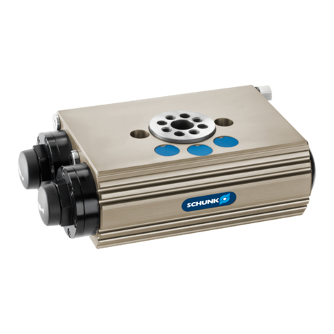
für Schwenkeinheit Type SRU 63
Assembly and Operating anual for
for Swivel Unit Type SRU 63
– The wear parts (seal kit and shock absorber) can be ordered
from SCHUNK.
– Lubrify the serration and the pinion during every maintenance
work with “Molykote BR2 plus” or an equivalent lubricant.
– All other sliding surfaces and seals have to be lubrified with
“Renolit HLT 2” or any equivalent grease.
– If not advised differently, secure all screws and nuts with
“Loctite No. 243”.
8.2 Assembly of the swivel unit
1. Remove all compressed air lines.
2. Unscrew the cover (item 16) and (item 11).
3. Mark the installation position of the pinion (item 2), the piston
(item 5). In case of a unit with integrated air feeding also mark
the position of the rotary transmission lead through (item 3).
4. Disassemble the pistons (item 5) at one side.
5. Disassemble the distribution flange (item 3) and the safety
ring (item 52).
6. Press the pinion (item 2) out of the housing.
7. Push the piston rods (item 30) and the pistons (item 5) out of
the housing.
8. Remove all sealings.
9. Clean all components
10. Check all components on damage and wear out.
Assembly is done in reverse order.
Hereby, please consider the notes at the beginning of this chapter .
Carefully assemble the rotary transmission lead through (item 3)
and make sure that no O-rings (item 44) will be damaged.
8.3 Disassembly and assembly of a shock
absorber
NOTE:
The shock absorbers are tested and are provided with this testing
number G 141. For all units with shock absorbers, only shock
absorbers with this testing numbers should be used. The shock
absorbers can be ordered from SCHUNK.
1. Loosen the lock nut (item 54) and unscrew the shock
absorber (item 32) and the sealing (item 49) out of the
adjustment sleeve (item 10).
2. Screw the new shock absorber (item 32) into the adjustment
sleeve (item 10) until it has reached its end position.
3. Place the O-Ring (item 49) into position and fasten the lock nut
(item 54).
8.4 Adjustment of the shock absorbers
In order to adjust the shock absorber set the adjustment screw to
a medium level. If the damping is too soft (the piston impacts on
the back stop at the end of the damping stroke), increase the
damping by turning the adjustment screw towards "0". Maximum
damping is achieved when the adjustment screw is set to "0".
If the damping is too hard (the piston impacts excessively hard on
the shock absorber at the beginning of the damping stroke) the
adjustment should be reduced by turning the adjustment screw
towards "9". Mininum damping is achieved at "9".
Internal damage to the shock absorber can occur if it is not
adjusted gradually.
WARNING
A badly adjusted shock absorber can reduce the life
time of your swivel unit.
– Die Verschleißteile (Dichtsatz und Stoßdämpfer) können Sie
bei SCHUNK bestellen.
– Fetten Sie bei der Wartung die Verzahnung und das Ritzel
mit »Molykote BR 2 plus« oder einem gleichwertigen
Schmierstoff.
– Alle anderen Gleitflächen und Dichtungen mit »Renolit HLT 2«
oder einem gleichwertigen Fett einfetten.
– Soweit nicht anders vorgeschrieben, sichern Sie alle
Schrauben und Muttern mit Loctite Nr. 243.
8.2 Zerlegen der Schwenkeinheit
1. ntfernen Sie die Druckleitungen.
2. Schrauben Sie die Deckel (Pos. 16) und (Pos. 11) ab.
3. Markieren Sie die inbaulage des Ritzels (Pos. 2), der Kolben
(Pos. 5) und bei der Ausführung mit integrierter Luftdurch-
führung die der Drehdurchführung (Pos. 3).
4. Demontieren Sie auf einer Seite die Kolben (Pos. 5).
5. Demontieren Sie den Verteilerflansch (Pos. 3) und den
Sicherungsring (Pos. 52).
6. Drücken Sie das Ritzel (Pos. 2) aus dem Gehäuse.
7. Schieben Sie die Kolbentange (Pos. 30) und die Kolben
(Pos. 5) aus dem Gehäuse.
8. ntfernen Sie alle Dichtungen.
9. Reinigen Sie alle Teile.
10. Kontrollieren Sie alle Teile auf Defekt und Verschleiß.
Der Zusammenbau erfolgt in umgekehrter Reihenfolge.
Beachten Sie dabei die Hinweise am Anfang des Abschnitts.
Gehen Sie beim inbau der Drehdurchführung (Pos. 3) vor sichtig
vor, damit Sie die O-Ringe (Pos. 44) nicht beschädigen.
8.3 Aus- und Einbau eines Stoßdämpfers
HINWEIS:
Die Stoßdämpfer werden einem Prüfverfahren unterzogen und
mit der Prüfnummer G 141 versehen. In allen inheiten mit Stoß -
dämpfern dürfen nur Stoßdämpfer mit Prüfnummer verwendet
werden. Die Stoßdämpfer können Sie bei SCHUNK beziehen.
1. Lösen Sie die Kontermutter (Pos. 54) und schrauben Sie den
Stoßdämpfer (Pos. 32) zusammen mit der Dichtung (Pos. 49)
aus der instellhülse (Pos. 10).
2. Schrauben Sie den neuen Stoßdämpfer (Pos. 32) bis zum
Anschlag in die instellhülse (Pos. 10).
3. Positionieren Sie den O-Ring (Pos. 49) und ziehen Sie die
Kontermutter (Pos. 54) fest.
8.4 Einstellen des Stoßdämfers
Zur Bestimmung des Härtegrades instellschraube auf mittleren
Wert einstellen. Ist die Dämpfung zu weich (Kolben trifft hart auf
den ndanschlag am nde des Dämfungshubes), erhöhen Sie
kontinuierlich die Dämpfung durch Drehen der instellschraube
in Richtung Skalenwert 0. Die maximale Dämpfung ist beim
Skalenwert 0 erreicht.
Ist die Dämpfung zu hart (Kolben trifft hart auf den Stoßdämpfer
am Anfang des Dämpfungshubes), verringern Sie die Dämpfung
durch Drehen der instellschraube in Richtung Skalenwert 9. Die
minimale Dämfung ist beim Skalenwert 9 erreicht.
Die instellung des Härtegrades muss schrittweise erfolgen, da
ansonsten Beschädigungen des Stoßdämpfers auftreten können.
WARNUNG:
Ein falsch eingestellter Stoßdämpfer kann die
Lebensdauer ihrer Schwenkeinheit beeinträchtigen.
