manuals.online logo
Brands
  1. Home
  2. •
  3. Brands
  4. •
  5. Emerson
  6. •
  7. Controllers
  8. •
  9. Emerson MR98 Series User manual

Emerson MR98 Series User manual

Other manuals for MR98 Series

2

This manual suits for next models

2

Other Emerson Controllers manuals

Emerson Bettis RTS User manual

Emerson

Emerson Bettis RTS User manual

Emerson E2 RX Series Manual

Emerson

Emerson E2 RX Series Manual

Emerson PACSystems RX3i User manual

Emerson

Emerson PACSystems RX3i User manual

Emerson PACSystems RX3i IC695CPE330 User manual

Emerson

Emerson PACSystems RX3i IC695CPE330 User manual

Emerson Fisher FIELDVUE DVC6200 HW2 Configuration guide

Emerson

Emerson Fisher FIELDVUE DVC6200 HW2 Configuration guide

Emerson Fisher 92C User manual

Emerson

Emerson Fisher 92C User manual

Emerson BETTIS RTS FQ User manual

Emerson

Emerson BETTIS RTS FQ User manual

Emerson ControlWave User manual

Emerson

Emerson ControlWave User manual

Emerson Dixell XEV20D User manual

Emerson

Emerson Dixell XEV20D User manual

Emerson EC3-D72 User manual

Emerson

Emerson EC3-D72 User manual

Emerson Fisher 4194S User manual

Emerson

Emerson Fisher 4194S User manual

Emerson Fisher FIELDVUE DVC6200 SIS User manual

Emerson

Emerson Fisher FIELDVUE DVC6200 SIS User manual

Emerson EIM 2000 Series User manual

Emerson

Emerson EIM 2000 Series User manual

Emerson FRANSEL REGAL 3 User manual

Emerson

Emerson FRANSEL REGAL 3 User manual

Emerson uerdant VX Series User manual

Emerson

Emerson uerdant VX Series User manual

Emerson Alco Controls PS1 Series User manual

Emerson

Emerson Alco Controls PS1 Series User manual

Emerson Fisher FIELDVUE L2t User manual

Emerson

Emerson Fisher FIELDVUE L2t User manual

Emerson PMAC II User manual

Emerson

Emerson PMAC II User manual

Emerson Fisher L2e User manual

Emerson

Emerson Fisher L2e User manual

Emerson TESCOM 44-6800 E Series User manual

Emerson

Emerson TESCOM 44-6800 E Series User manual

Emerson XM678D Specification sheet

Emerson

Emerson XM678D Specification sheet

Emerson MR105 User manual

Emerson

Emerson MR105 User manual

Emerson 6351F User manual

Emerson

Emerson 6351F User manual

Emerson Dixell XR60CHC Wiring diagram

Emerson

Emerson Dixell XR60CHC Wiring diagram

Popular Controllers manuals by other brands

Sunricher SR-ZV9003T3-RGBW-US Installation

Sunricher

Sunricher SR-ZV9003T3-RGBW-US Installation

Ksenia intro Installation and configuration manual

Ksenia

Ksenia intro Installation and configuration manual

Inovance CAN200 Series manual

Inovance

Inovance CAN200 Series manual

Gauzy LC6 FLEX Controller Installation and operation guide

Gauzy

Gauzy LC6 FLEX Controller Installation and operation guide

Viking SLP-1 Technical practice

Viking

Viking SLP-1 Technical practice

CKD KBX-30E-U Series instruction manual

CKD

CKD KBX-30E-U Series instruction manual

Sharp Energy Sun Flux User manual & installation guide

Sharp Energy

Sharp Energy Sun Flux User manual & installation guide

Yamaha RCX40 user manual

Yamaha

Yamaha RCX40 user manual

AB Quality PowerFlex 400 Frames D-H Service bulletin

AB Quality

AB Quality PowerFlex 400 Frames D-H Service bulletin

Yamaha MJC8 owner's manual

Yamaha

Yamaha MJC8 owner's manual

AL-KO ATC operating instructions

AL-KO

AL-KO ATC operating instructions

Savant SmartControl 2 Deployment guide

Savant

Savant SmartControl 2 Deployment guide

GameSir T3S user manual

GameSir

GameSir T3S user manual

Kostal inveor operating manual

Kostal

Kostal inveor operating manual

CoCo ACM-LV24 Quick installation guide

CoCo

CoCo ACM-LV24 Quick installation guide

Brooks SLA5810/20 Installation and operation manual

Brooks

Brooks SLA5810/20 Installation and operation manual

SIGMA TEK SR 011 Technical manual

SIGMA TEK

SIGMA TEK SR 011 Technical manual

Aprilaire 76 installation instructions

Aprilaire

Aprilaire 76 installation instructions

manuals.online logo
manuals.online logoBrands
  • About & Mission
  • Contact us
  • Privacy Policy
  • Terms and Conditions

Copyright 2025 Manuals.Online. All Rights Reserved.

P1757_1
P1753_1
D-A-CH Region Only
MR98 Series Backpressure Regulators and
Relief Valves – AD2000 Compliant
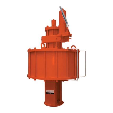
Figure 1. Typical MR98 Series Backpressure Regulators and Relief Valves
TYPE MR98H WITH FLANGE END CONNECTION
TYPE MR98H
 April 2022
MR98 Series AD2000 Compliant
Instruction Manual
D104615X012
2
MR98 Series AD2000 Compliant
D-A-CH Region Only
Specications
This section lists the specications for the MR98 Series Regulators. Factory specication such as type, maximum
inlet pressure, maximum temperature, maximum outlet pressure, spring range, orice size and seat material are
stamped on the nameplate fastened on the regulator at the factory.
1. The pressure/temperature limits in this Instruction Manual and any applicable standard limitation should not be exceeded.
2. Pressure and/or the body end connection may decrease the maximum temperatures.
Available Constructions
Type MR98H: Backpressure regulator/relief valve
for spring settings range from 5 to 200 psig /
0.34 to 13.8 bar.
Type MR98HH: Backpressure regulator/relief
valve for spring settings range from 150 to
375 psig / 10.3 to 25.9 bar.
Body and Orice Sizes
1/2 in. / DN 15: 0.416 in. / 10.56 mm
3/4 and 1 in. / DN 20 and 25:
0.631 in. / 16.02 mm
1-1/2 and 2 in. / DN 40 and 50:
1.142 in. / 29 mm
Body End Connections
See Tables 1
Set Pressure Ranges(1)
See Table 2
Maximum Cold Working Pressures of Body Size
and Materials(1)
See Table 3
Maximum Inlet, Outlet and Spring Case
Pressure Ratings(1)
See Table 3
Maximum Temperature Ranges of Diaphragm, Seat,
Trim and Body Materials(1)(2)
See Table 4
Flow Coe󰀩cients
IEC Sizing Coe󰀩cients
Pressure Registration
Internal or External
Shuto󰀨 Classication Per ANSI/FCI 70-3-2004
Metal Seats: Class IV
Polytetrauoroethylene (PTFE): Class IV
Elastomer Seats: Class VI or better
Sour Gas Service Capability
Optional materials are available for applications
handling sour gases. These constructions comply
with the recommendations of NACE International
Standards MR0175-2002, NACE MR0103 and/or
NACE MR0175/ISO 15156.
API 614 Compliant
Steel or Stainless steel constructions with
Stainless steel trim meet API 614 Requirements.
Approximate Weights
MR98H Series:
1/2 in. / DN 15: 10 lbs / 4.5 kg
3/4 and 1 in. / DN 20 and 25: 22 lbs / 10 kg
1-1/2 and 2 in. / DN 40 and 50: 55 lbs / 25 kg
BODY SIZE CvCgC1
NPS DN
1/2 15 3.4 120 35.3
3/4 and 1 20 and 25 6.5 250 38.5
1-1/2 and 2 40 and 50 20.0 780 39.0
BODY SIZE XTFdFLKm
NPS DN
1/2 15 0.787 0.78 0.94 0.88
3/4 and 1 20 and 25 0.935 0.70 0.91 0.83
1-1/2 and 2 40 and 50 0.961 0.69 0.94 0.88
3
MR98 Series AD2000 Compliant
D-A-CH Region Only
Table 1. Types MR98H and MR98HH Regulators Body Constructions
BODY SIZE BODY CONSTRUCTION END CONNECTION STYLE BODY MATERIAL
1.4408 Stainless Steel(1)
1/2 in. / DN 15
Without Control Line and Gauge Port
G Thread
SWE
Welded CL150 RF
Welded CL300 RF
Welded PN 16/25/40 RF
Integral CL150 RF
Integral CL300 RF
Integral PN 16/25/40 RF
With Control Line but Without Gauge Port
G Thread
Welded CL150RF
Welded CL300RF
3/4 in. / DN 20
Without Control Line and Gauge Port
G Thread
SWE
Welded CL150 RF
Welded CL300 RF
Welded PN 16/25/40 RF
With Control Line but Without Gauge Port
G Thread
Welded CL150 RF
Welded CL300 RF
With Gauge Port but Without Control Line
G Thread
Welded CL150 RF
Welded CL300 RF
Welded PN 16/25/40 RF
1 in. / DN 25
Without Control Line and Gauge Port
G Thread
SWE
Welded CL150 RF
Welded CL300 RF
Welded PN 16/25/40 RF
Integral CL150 RF
Integral CL300 RF
Integral PN 16/25/40 RF
With Control Line but Without Gauge Port
G Thread
Welded CL150 RF
Welded CL300 RF
With Gauge Port but Without Control Line
G Thread
Welded CL150 RF
Welded CL300 RF
Welded PN 16/25/40 RF
- Shaded areas indicate that the construction is available.
- Blank areas indicate that you need to contact your local Sales O󰀩ce for the availability of the constructions.
1. Meets the chemical and physical requirements of NACE MR0175-2002, NACE MR0103 and NACE MR0175/ISO 15156.
- continued -
4
MR98 Series AD2000 Compliant
D-A-CH Region Only
Table 1. Types MR98H and MR98HH Regulators Body Constructions (continued)
BODY SIZE BODY CONSTRUCTION END CONNECTION STYLE BODY MATERIAL
1.4408 Stainless Steel(1)
1-1/2 in. / DN 40
Type MR98H only
Without control line and gauge port
G Thread
SWE
Welded CL150 RF
Welded CL300 RF
Welded PN 16/25/40 RF
With control line but without gauge port
G Thread
Welded CL150 RF
Welded CL300 RF
With gauge port but without control line
G Thread
Welded CL150 RF
Welded CL300 RF
Welded PN 16/25/40 RF
2 in. / DN 50
Type MR98H only
Without control line and gauge port
G Thread
SWE
Welded CL150RF
Welded CL300RF
Welded PN 16/25/40 RF
Integral CL150 RF
Integral CL300 RF
Integral PN 16/25/40 RF
With control line but without gauge port
G Thread
Welded CL150 RF
Welded CL300 RF
With gauge port but without control line
G Thread
Welded CL150 RF
Welded CL300 RF
Welded PN 16/25/40 RF
- Shaded areas indicate that the construction is available.
- Blank areas indicate that you need to contact your local Sales O󰀩ce for the availability of the constructions.
1. Meets the chemical and physical requirements of NACE MR0175-2002, NACE MR0103 and NACE MR0175/ISO 15156.
5
MR98 Series AD2000 Compliant
D-A-CH Region Only
Table 2.MR98 Series Body Sizes, Pressure Ranges and Spring Information
TYPE
BODY SIZE CONTROL
PRESSURE RANGE(1)
SPRING WIRE
DIAMETER
SPRING FREE
LENGTH SPRING MATERIAL(2) SPRING PART
NUMBER SPRING COLOR
NPS DN psig bar In. mm In. mm
MR98H
1/2 15
15 to 35 1.0 to 2.4 0.207 5.26 2.50 63.5 Powder-coated steel(3) ERCA04288A0 Yellow
25 to 75 1.7 to 5.2 0.234 5.94 2.595 65.9 Powder-coated steel(3) ERAA01910A0 Green
70 to 140 4.8 to 9.7 0.283 7.19 2.44 62.0 Powder-coated steel(3) ERAA01911A0 Red
130 to 200 9.0 to 13.8 0.331 8.41 2.250 57.2 Powder-coated steel(3) ERAA02889A0 Blue
3/4
and 1
20
and 25
15 to 35 1.0 to 2.4 0.306 7.77 4.00 102 Powder-coated steel(3) 1E398927022 Yellow
25 to 75 1.7 to 5.2 0.343 8.71 4.00 102 Powder-coated steel(3) 1E399027142 Green
70 to 140 4.8 to 9.7 0.406 10.3 4.00 102 Powder-coated steel(3) 1E399127162 Red
130 to 200 9.0 to 13.8 0.468 11.9 3.75 95.3 Powder-coated steel 1L380127082 Blue
3/4
and 1
20
and 25
15 to 35 1.0 to 2.4 0.306 7.77 4.00 102 Powder-coated Stainless steel 1E3989X0052 Yellow
25 to 75 1.7 to 5.2 0.375 9.53 3.88 98.6 Stainless steel 1K762537022 Unpainted
70 to 140 4.8 to 9.7 0.437 11.1 4.00 102 Stainless steel 11A8269X012 Unpainted
1-1/2
and 2
40
and 50
5 to 35 0.34 to 2.4 0.468 11.9 6.562 167 Powder-coated steel(4) 1E792327092 Dark gray
20 to 65 1.4 to 4.5 0.500 12.7 6.50 165 Powder-coated steel(4) ERCA04290A0 Black with light blue stripe
50 to 100 3.4 to 6.9 0.562 14.3 6.562 167 Powder-coated steel(5) ERAA01893A0 Light gray
75 to 170 5.2 to 11.7 0.625 15.9 6.565 167 Powder-coated steel(5) 1P7888X0022 Black
MR98HH
1/2 15 150 to 375 10.3 to 25.9 0.394 10.0 5.063 129 Powder-coated steel 1N943427142 Unpainted
3/4
and 1
20
and 25 150 to 340 10.3 to 23.4 0.593 15.1 6.380 162 Chromium-silicon steel 1N9441X0022 Light gray
1. All springs may be backed o󰀨 to 0 psig / 0 bar. However, highest capacities and best performances are obtained by using these springs in their recommended ranges.
2. Springs meet NACE MR0175-2002, NACE MR0103 and NACE MR0175/ISO 15156 requirements only for applications in which the spring is not exposed to the sour gas.
3. Available in Inconel®.
4. Spring range changes to 5 to 60 psig / 0.34 to 4.1 bar for the Inconel® option.
5. Spring range changes to 50 to 120 psig / 3.4 to 8.3 bar for the Inconel® option.
Inconel® is a mark owned by Special Metals Corporation.
Table 3. Maximum Cold Working Pressures of Body Size and Materials(1)(2)
REGULATOR
TYPE
BODY SIZE BODY AND SPRING
CASE MATERIALS
MAXIMUM INLET PRESSURE(3) MAXIMUM OUTLET PRESSURE MAXIMUM SPRING
CASE PRESSURE
NPS DN psig bar psig bar psig bar
MR98H 1/2, 3/4, 1,
1-1/2, 2
15, 20, 25,
40, 50 Stainless steel 300 20.7 300 20.7 300 20.7
MR98HH
1/2 15
Stainless steel
400 27.6 400 27.6 400 27.6
3/4, 1 20, 25 340 23.4 340 23.4 340 23.4
1. The pressure/temperature limits in this Installation Manual and any applicable standard limitation should not be exceeded.
2. Temperature, trim material and/or the body end connection may decrease these maximum pressures.
3. Maximum inlet pressure equals set pressure plus build-up.
Table 4. Temperature Capabilities(1)(2)(5)
MATERIAL SEAT DIAPHRAGM O-RING DIAPHRAGM
PROTECTOR
TEMPERATURE
°F °C
Nitrile (NBR)   -40 to 180 -40 to 82
Neoprene (CR) -40 to 180 -40 to 82
Fluorocarbon (FKM)(3)    0 to 300,
Limited to 200°F for hot water
-18 to 149,
Limited to 93°C for hot water
Ethylenepropylene (EPDM)    20 to 275 -7 to 135
Peruoroelastomer (FFKM)   0 to 425 -18 to 218
PTFE -40 to 400 -40 to 204
Metal   -40 to 450 -40 to 232
BODY MATERIAL
TEMPERATURE
°F °C
1.4408 Stainless steel(4) -40 to 450 -40 to 232
1. The pressure/temperature limits in this Instruction Manual and any applicable standard limitation should not be exceeded.
2. Pressure and/or the body end connection may decrease these maximum temperatures.
3. Not for use on steam service.
4. Meets API 614 requirements (with Stainless steel trim).
6
MR98 Series AD2000 Compliant
D-A-CH Region Only
▲ WARNING
Failure to follow these instructions or
to properly install and maintain this
equipment could result in an explosion,
re and/or chemical contamination
causing property damage and personal
injury or death.
Fisher™ backpressure regulators,
relief and relief valves must be
installed, operated and maintained
in accordance with federal, state and
local codes, rules and regulations and
Emerson instructions.
If a leak develops or if the outlet
continually vents gas, service to the
unit may be required. Failure to correct
trouble could result in a hazardous
condition. Only a qualied person shall
install or service the unit.
Installation, operation and maintenance
procedures performed by unqualied
person may result in improper adjustment
and unsafe operation. Either condition
may result in equipment damage or
personal injury. Call a qualied person
when installing, operating and maintaining
the MR98 Series Backpressure Regulators,
Relief and Relief Valves.
Introduction
Scope of the Manual
This manual provides instructions for the installation,
adjustment, maintenance and parts ordering
information of MR98 Series Backpressure Regulators
and Relief Valves. Instructions and parts lists for other
equipment mentioned in this Instruction Manual are
found in separate manuals.
Product Description
The MR98 Series Backpressure Regulator and Relief
Valves are suitable for multiple uid mediums including
liquid, gas, air and steam services. Typical applications
include use in but not limited to wash tanks, small
heaters, fuel and oil lines, air supply system, test
xtures and sterilizers.
Backpressure Regulator / Pressure Relief Valve—
Types MR98H and MR98HH Regulators are
direct-operated backpressure regulator/relief valve for
pressure control requiring constant outlet pressures
between 2 to 375 psig / 0.14 to 25.9 bar.
See Tables 1 through 4 for detailed breakdown of the
various construction o󰀨erings.
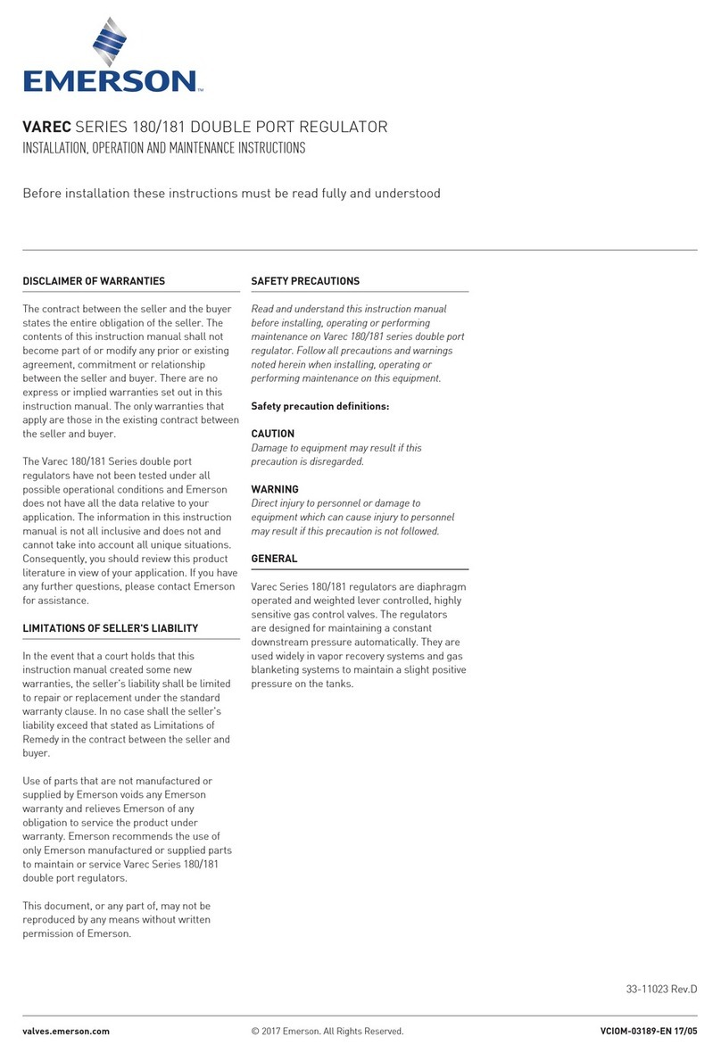
Principle of Operation
Relief or backpressure valves respond to changes in
upstream pressure. Pressure changes register under
the diaphragm (see Figure 2) through a registration hole
in the valve body or through an external control line.
When the pressure increases above the spring setting,
the pressure underneath the diaphragm overcomes the
spring compression. This causes the valve plug to move
away from the orice. The ow path through the valve
is open and excess pressure is vented. When upstream
pressure drops below setpoint, the valve closes.
Installation
▲ WARNING
Personal injury or system damage may
result if this backpressure regulator or
relief valve is installed where service
conditions could exceed the limits given
on the Specications section and/or
regulator nameplate.
Additionally, physical damage to the
backpressure regulator or relief valve
may result in personal injury or property
damage due to escaping of accumulated
gas. To avoid such injury and damage,
install the backpressure regulator or
relief valve in a safe location.
Under enclosed conditions or indoors,
escaping gas may accumulate and be an
explosion hazard. In this case, the vent
should be piped outdoors.
For regulator constructions with a
spring case vent, the vent should be
kept open to permit free ow of gas
to the atmosphere. Protect openings
against entrance of rain, snow, insects
or any other foreign material that may
plug the spring case vent or vent line.
INLET PRESSURE
OUTLET PRESSURE
ATMOSPHERIC PRESSURE
M1240_12/2019 M1239_12/2019
7
MR98 Series AD2000 Compliant
D-A-CH Region Only
ADJUSTING SCREW
CONTROL SPRING
VENT
DIAPHRAGM
VALVE PLUG
ORIFICE
CONTROL LINE TAP
1/2 in. / DN 15 TYPE MR98H
WITH EXTERNAL
PRESSURE REGISTRATION
TYPE MR98H WITH INTERNAL
PRESSURE REGISTRATION
SIDE AND INTERNAL VIEW OF
3/4 TO 2 in./ DN 20 TO 50
TYPE MR98H WITH EXTERNAL
PRESSURE REGISTRATION
METAL DIAPHRAGMS
SPRING
GASKET
FOR TYPE MR98H WITH TWO METAL DIAPHRAGMS
(ALSO TYPICAL OF TYPE MR98HH)
ATMOSPHERIC PRESSURE
OUTLET PRESSURE
INLET PRESSURE
Figure 2. MR98 Series Operational Schematics
8
MR98 Series AD2000 Compliant
D-A-CH Region Only
Overpressure Protection
▲ WARNING
Overpressuring any portion of
this equipment may result in
equipment damage, leaks in the
relief valve/backpressure regulator
or personal injury due to bursting of
pressure-containing parts.
Relief or backpressure ranges are from 2 to 375 psig /
0.14 to 25.9 bar. The individual spring range of your
valve is stamped on the nameplate.
Maximum inlet pressure depends upon body
materials and temperatures. See Specications
section or the maximum inlet pressure of the valve.
The valve should be inspected for damage after any
overpressure condition.
Vents and Relief Valve Outlet
▲ WARNING
If using an MR98 Series Backpressure
Regulator or Relief Valve on hazardous
or ammable gas service, personal
injury and property damage could occur
due to re or explosion of vented gas
that may have accumulated.
To prevent such injury or damage,
provide piping or tubing to vent the
gas to a safe, well-ventilated area. All
vents should be kept open to permit free
ow of gas to the atmosphere. Protect
openings against entrance of rain, snow,
insects or any other foreign material that
may plug the vent or vent line.
If remote venting is necessary, a tapped vent in the
spring case is available. Install remote vent lines in the
spring case and outlet openings. The vent lines must
have the largest practical diameter and be as short as
possible with a minimum number of bends or elbows.
Install the vent line according to applicable federal, state
and local codes and regulations.
Startup
Note
The Specications section and
Table 3 show the maximum inlet and
di󰀨erential pressures for specic
constructions. Use pressure gauges
to monitor inlet pressure, outlet
pressure and any loading pressure
during startup.
Key numbers are shown in Figures 3 through 5.
1. Check that proper installation is completed and
downstream equipment has been properly adjusted.
2. Make sure all block and vent valves are closed.
3. Decompress the control spring by turning
the adjusting screw (for Types MR98H and
MR98HH) counterclockwise.
4. Slowly open the valves in the following order:
a. Loading supply and control line valve(s), if used
b. Inlet block valve
c. Outlet block valve
5. Set the regulator to the desired set pressure
according to the Adjustment procedure.
Adjustment
Each unit is factory set for the pressure setting
specied on the order or at the mid-point of the spring
range. The allowable spring range is stamped on the
nameplate. If a pressure setting beyond the indicated
range is required, replace with the appropriate spring.
Be sure to label the regulator/valve to indicate the new
pressure range.
Before installing the regulator:
• Unpack the backpressure regulator or relief valve
and remove the protective shipping plugs from
the end connections of the body and the pressure
connection in the spring case.
• Check the backpressure regulator or relief valve
and make sure it has not been damaged or
collected foreign material during shipping.
• Remove any debris or dirt in the tubing and
the pipeline.
• Apply pipe compound to the external pipe thread
for NPT bodies or use appropriate gaskets for
anged bodies.
• Make sure gas ow through the backpressure
regulator or relief valve is in the same direction as
the arrow on the body.
9
MR98 Series AD2000 Compliant
D-A-CH Region Only
Always use a pressure gauge to monitor pressure
when making adjustments.
All MR98 Series Regulator springs can be backed o󰀨
to zero pressure. Recommended set pressure ranges
available, maximum inlet pressures and temperatures
and color codes of the respective springs are shown in
the Specications section and Table 2.
Types MR98H and MR98HH
1. Loosen the jam nut (key 17, Figures 3, 4 and 5).
2. To increase the set pressure or pressure setting,
turn the adjusting screw (key 15) clockwise. Turn
the adjusting screw counterclockwise to decrease
the set pressure or pressure setting.
3. Tighten the jam nut (key 17).
Shutdown
Relief Valve
1. Close the upstream shuto󰀨 valve to the
regulator inlet.
2. Close the downstream shuto󰀨 valve to the
regulator outlet.
3. Slowly open the downstream vent valve to vent
downstream pressure.
4. Leave the downstream vent valve open to vent
inlet pressure and to release all remaining
pressure in the regulator by opening the upstream
vent valve or by turning the adjusting screw
fully counterclockwise.
Backpressure Regulator
1. Close the upstream shuto󰀨 valve to the
regulator inlet.
2. Close the downstream shuto󰀨 valve to the
regulator outlet.
3. To avoid internal damage due to reverse
pressurization of main valve components, bleed
backpressure regulator inlet pressure rst before
bleeding outlet pressure.
Maintenance
▲ WARNING
To avoid personal injury, property
damage or equipment damage caused
by sudden release of pressure or
explosion of accumulated gas, do not
attempt any maintenance or disassembly
without rst isolating the relief valve
or regulator from system pressure and
relieving all internal pressure from the
relief valve or regulator.
To avoid possible personal injury from
spring or pressure-loaded actuator,
make sure that the adjusting screw is
completely backed o󰀨 or the spring case
pressure is vented prior to disassembly.
Otherwise, the spring load or loading
pressure could forcefully eject the
spring case.
Relief valves or regulators that have
been disassembled for repair must
be tested for proper operation before
being returned to service. Only parts
manufactured by Emerson should be
used for repairing Fisher™ relief valves
and regulators.
Due to normal wear or damage that
may occur from external sources, this
relief valve or backpressure regulator
should be inspected and maintained
periodically. The frequency of inspection
and replacement of parts depends upon
the severity of service conditions or the
requirement of local, state and federal
rules and regulations.
Due to normal wear and damage that may occur from
external sources, relief valve parts such as the O-rings,
gaskets, diaphragm, orice and valve plug should be
inspected periodically and replaced as necessary. The
frequency of inspection and replacement depends upon
the severity of service conditions or the requirements of
state and federal laws.
Instructions are given below for disassembly of
the MR98 Series. These valves do not have to be
removed from the pipeline to inspect internal parts.
Suitable lubricants are indicated on the assembly
drawings. Apply the recommended lubricants as
the relief valve is being reassembled. Refer to
Figures 3 to 5 while servicing the relief valve.
10
MR98 Series AD2000 Compliant
D-A-CH Region Only
Table 5. Torque Specifications
BODY SIZE SPRING CASE BOLTS(1) ORIFICE VALVE PLUG GUIDE BOTTOM PLUG
NPS DN Ft-lbs N•m Ft-lbs N•m Ft-lbs N•m Ft-lbs N•m
1/2
3/4 and 1
1-1/2 and 2
15
20 and 25
40 and 50
10 to 13
24 to 30
40 to 50
13 to 18
33 to 41
54 to 68
34 to 38
50 to 60
180 to 200
46 to 51
68 to 81
244 to 271
70 to 90
85 to 100
125 to 150
94 to 122
115 to 136
169 to 203
75 to 90
100 to 125
170 to 200
102 to 122
136 to 169
230 to 271
1. Reduce spring case bolt’s torque by 30% when using Ethylenepropylene (EPDM) diaphragms.
Note: Pusher post lock nut (key 31) should be installed with an additional 1/8 to 1/4 turn when washer is at. See step 10 in the “Disassembly to Replace Diaphragm and Seats” section or
detailed instruction.
Flange Cap Screw Torque Inspection
Retorquing of spring case cap screws may be
necessary for some MR98 Series Regulators after a
period of use. Retorque the cap screws as follows:
1. Shut down the relief valve or backpressure
regulator. Refer to Shutdown section for the
proper procedure.
2. Retighten the cap screws (key 16) in a crisscross
pattern. See Table 5 for proper torque values.
3. Follow the Startup section to repressurize the relief
valve or backpressure regulator.
4. Refer to the Disassembly to Replace Diaphragm
and Seats section as needed.
Disassembly to Replace Diaphragm
and Seats
△ CAUTION
Metal diaphragms have thin sharp
edges. To avoid hand cuts, be careful
when handling the diaphragm,
particularly the diaphragm edge.
If the relief valve is leaking, the diaphragm may be
ruptured or the seating surfaces nicked or scratched.
Proceed as follows to inspect or replace the
diaphragm, orice and valve plug.
1. Shut down the backpressure regulator or
relief valve. Refer to Shutdown section for the
proper procedure.
2. For Types MR98H and MR98HH: Relieve
the spring tension by loosening the jam
nut (key 17) and turning the adjusting
screw (key 15) counterclockwise.
3. Remove cap screws (key 16) and lift o󰀨 the
spring case (key 2), upper spring seat (key 9)
and relief valve spring (key 11). Lift out the
diaphragm unit which includes the lock nut
(key 31), lock washer (key 28), pusher post
(key 10), gasket (key 29), lower spring seat (key 8),
diaphragm (key 12), diaphragm head (key 21 for
Type MR98H, 1-1/2 and 2 in. / DN 40 and 50 body
sizes) and valve plug (key 4).
4. Check the orice (key 3) for wear or damage. If it
needs to be replaced, unscrew the valve plug guide
(key 7) and then the orice. The valve plug (key 4)
can be removed by sliding it o󰀨 of the pusher
post (key 10).
5. Place a small amount of sealant on the threads
of the orice (key 3) and valve plug guide (key 7)
and reinstall these to the body (key 1). See
Table 5 for torque specications.
6. To replace the valve plug O-ring (key 53), remove
the machine screw (key 24) and O-ring retainer
(key 25) from the plug. Remove and replace
the O-ring.
7. Separate the remainder of the diaphragm unit
parts. Take the lock nut (key 31) o󰀨 of the pusher
post (key 10). Slide o󰀨 the lock washer (key 28),
lower spring seat (key 8), diaphragm head (key 21
for Type MR98H, 1-1/2 and 2 in. / DN 40 and 50
body sizes), diaphragm (key 12), washer (key 58)
and gasket (key 29).
8. Slip the valve plug (key 4) onto the pusher post
(key 10). Place a gasket (key 29) on the shaft
of the pusher post over the threaded portion
until it rests on the base of the post. If elastomer
diaphragm (key 12) is used, place a metal washer
(key 58) on top of the gasket. For Type MR98H,
1-1/2 to 2 in. / DN 40 to 50 with metal diaphragm,
place another gasket on the shaft of the pusher
post until it rests on the bottom diaphragm head
(key 21), see Figure 4.