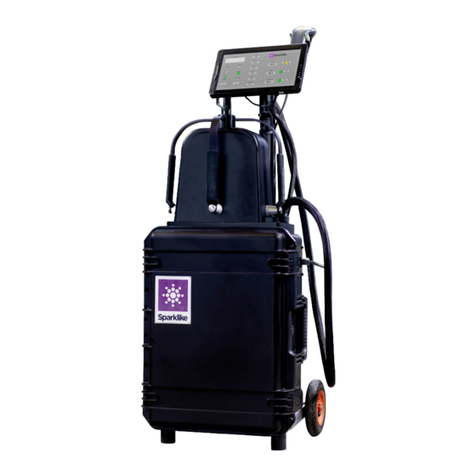
sparklike GasGlass User manual

2 Connections
2 Setting up the Gasglass Laser
4 Starting to use the equipment
6 Taking a measurement
8 Troubleshooting
12 Service & maintenance
GASGLASS LASER
INSTRUCTION MANUAL
PAGE

SPARKLIKE GASGLASS LASER
Thank you for choosing Gasglass Laser to measure the gas concentrations
on your insulating glass products. Gasglass Laser is a unique product for
non-invasive analysis, that measures even through coatings. Gasglass Laser measures oxygen,
and therefore the results can be converted to argon and krypton, just as well as xenon.
2
Before operating the equipment - connect the three parts with provided cables.
Follow the instructions carefully before starting the device. We recommend also to register
your device at our website for more straightforward service to your device.
www.sparklike.com/register-your-device
NOTIFICATIONS:
· Do not position the equipment in a way that it would be difficult to reach and operate the
power cable.
· If the equipment is used in a manner not specified by the manufacturer, the safety
protection of the equipment may be compromised.
· Do not replace detachable mains supply cords by inadequately rated cords.
· Always make sure that you are using a safety grounded socket with safety grounded
mains supply cord to connect the mains supply.
· Main fuse is located inside the power connector
Europe: 250 V, T, 1,25 A, USA and Asia: 250 V, T, 2,5 A
The equipment consists of 3 parts : Main unit: 500 x 350 x 132 (L x W x H, in mm),
measuring head: 350 x 150 x 350 ( L x W x H, in mm) Display: 10,1” Touch Screen with pen.
2
Signal cables, 4 pcs
Double USB,
Ethernet, HDMI, 12V
socket, power switch
& power cord
SPARKLIKE GASGLASS LASER SPECIFICATIONS
Laser Classification The Sparklike GasGlass Laser device uses a Vertical-Cavity-
Surface-Emitting-Laser (VCSEL) as a light source. According
to the regulations, the VCSEL is tested by a third party
as class 1 laser product (SGS-CSTC Standards Technical
Services Co. Ltd., test report GZES150500576331)
Laser Specifications Wavelenght: 760 nm
Maximum optical output power: 3 mW
Maximum single mode output power: 0,6 mW
Classification: Class 1
Visibility: NIR (Near Infrared)
Class 1 Laser product Cannot emit laser radiation at known hazard levels. Users of Class
1 laser products are generally exempt from radiation hazard
controls during operations and maintenance. Class 1 laser is eye-
safe under normal operating conditions.
Standards and Regulations IEC 60825-1: 2014 (Third edition)
Surface-Emitting-Laser (VCSEL) as a light source. According
to the regulations, the VCSEL is tested by a third party
as class 1 laser product (SGS-CSTC Standards Technical
Services Co. Ltd., test report GZES150500576331)

1 CONNECTIONS
2 STARTING UP THE GASGLASS LASER
SETTING UP THE SYSTEM
After connecting all the cables, turn on the device from the power switch on the main unit.
Windows will start and “Start” button’s led on the measuring device’s handle will light up.
After Windows has started, start GGLaser software. Sparklike logo shaped indicator light on
the measuring device should light up.
If either of the leds do not turn on, please restart the software from
the screen (see troubleshooting section in Chapter 5)
Connect all 3 (4 on manual devices) signal cable plugs from measuring head to the match-
ing sockets on the main unit.
Connect the HDMI to HDMI+USB cable and the power cable to the display and to the main
unit. (In older models the display is connected only with dual USB cable.)
Connect the provided power cord to the main unit and the other end to the mains power
outlet.
Ethernet connection is for online use only, and left disconnected in normal use.
ATTENTION: Please note that one of the signal plugs may have an extra socket attached to
the cable. If there is one, it needs to be connected to the ODU 10-pin at all times, when the
plug is not connected to the main unit socket. This is a safety feature for the laser against
ESD (electro-static-discharge).
Picture of the software
Indicator leds
on top of the
measuring head
and on the handle

4
3 STARTING TO USE THE EQUIPMENT
3.1 Software functionality and options for
measurement
STARTING UP THE DEVICE
“Measure” button will start the measure-
ment. It is also possible to start the mea-
surement directly from the measuring head
handle. For more information on taking the
measurement, read Chapter 4.
After the first start, on left hand side of the
window, you will see “Laser ON” and “TEC
ON” lights green. Below these, the “Laser
limit reached” and “TEC window exceeded”
should be off.
MEASUREMENT
RESULTS
Once using the
analyzer, you will
see your measure-
ment results on
the right hand side
of the screen. The
dimension’s col-
umn will give you a
result on the thick-
ness of the glass
and the space be-
tween the glasses.
You will get this
reading whilst your gas concentration mea-
surement is being calculated.
The concentration column gives you the re-
sults of the gas fill in each cavity once the
measurement is finished.
SETTINGS
You can write text to be added with your
measurement result using the on-screen
keyboard found in the Windows Task bar.
This information is saved to the file together
with your results. Use the text box labelled
“User information”.
Measurement
screen on the
software
“Measurement time” drop down box indi-
cates the time to collect data from one cav-
ity. This can be adjusted between 1–10 sec-
onds. Longer measurement time is advised
for greater accuracy.
If you activate “Enable counter” button, it is
possible to make multiple measurements
in a row. You can do this by pressing the
button. A green light is switched on.
If you have enabled counter, signal how
many measurements you would like to take
in a row. Select a number for “Meas. count”
box by clicking up or down, or by typing a
value with the on-screen keyboard.
Triple glass measurement is set as a default
for Gasglass Laser analyzer. It is possible to
measure also double glass products. Do this
by enabling double glass measurement by
pressing down “Double IG” button. This is
not necessary, but it will make the measure-
ment time quicker, and helps the operator
to interpret the results correctly.
“Glass” and “Spacer” drop down boxes can
be used to assist the software on intended
thickness measures.
Note: Measurement results are shown on
the screen, but are simultaneously saved on
your device, and can be accessed at Windows
Explorer: Computer\Local Disc(C:)\Temp\Results

STARTING TO USE THE EQUIPMENT
3.2 Daily operations for temperature
check and gas fill
AT EVERY START UP: The operator should
check for temperature and oxygen con-
centration. This ensures the correct opera-
tion of Gasglass Laser.
Temperature check
Laser component needs to be operated in
correct temperature in order to yield highly
accurate measurement results. Incorrect
temperature adjustment might result in in-
correct measurement results or unexpect-
ed functions. Take the following actions
to test the temperature adjustment every
time when starting up the device.
Choose the “Check and Gas fill” page from
the upper left corner on the software. Press
“Laser Test” button and see the following:
• Laser I should be 5,3 – 5,7mA and Laser
R 3 – 16 kΩ. Value is specific for each
device.
• Graph should be adjusted so that X
axis is approximately 500 points wide
and Y axis according to the height of
the spikes. This can be done from the
bottom left of the graph.
• Figures on the graph should be equally
spaced and with approximately 50 (in
older devices 100) points spacing.
If these are correct, press stop.
If these don’t apply, see troubleshooting
section in Chapter 5.
Oxygen concentration check
Gasglass Laser is a gas fill analyzer, however
it measures the oxygen absorption from the
insulating glass unit. For correct readings,
oxygen inside the measuring head needs
to be removed as well as pos-
sible. This is done by flushing
the measuring head with ar-
gon/xenon/nitrogen to replace
the oxygen.
On “Check and Gas Fill” page,
press “Self Check” button. This
will measure the oxygen con-
centration inside the measur-
ing head, and show the result
on the box below the button.
The operator can begin to use
the device if if the result is be-
low 0,15%.
If the result is over 0,15%,
there’s is too much oxygen inside the mea-
suring head and the following actions
should be taken:
• Place the measuring head facing
(glass window) down on unscratching
surface.
• Open the end cap from the left handle
on the measuring head, and take out
the two hoses.
• Apply dry and pure (>99,9 %) argon
flow of 1 – 3l/min to the hose marked
with “IN” label
• Press the “Gas fill” button on the
software (light on the button will turn
on). This will open the internal valves
and guide the argon flow through the
measuring head.
During the filling, press “Self Check” button
to check the concentration. On each check,
you should see the concentration to de-
crease. Continue filling as long as the con-
centration does not go any lower, and the
self-check result is < 0,15%.
Temperature check
Laser component needs to be operated in
sible. This is done by flushing
the measuring head with ar-
gon/xenon/nitrogen to replace
the oxygen.
On “Check and Gas Fill” page,
press “Self Check” button. This
will measure the oxygen con-
centration inside the measur-
ing head, and show the result
on the box below the button.
The operator can begin to use
the device if if the result is be-
low 0,15%.
ing head, and show the result
on the box below the button.
The operator can begin to use
the device if if the result is be-
low 0,15%.
Gas fill and
temperature
check screen
on the software

6
4 TAKING A MEASUREMENT
MEASUREMENT
Place the measuring head front cushion
firmly against the window. It is possible to
start the device in two alternative ways:
• Press the “Measure” button on the
“Measurement” page of the software.
• Press the “Start” button directly on the
right handle of the device.
Vacuum pump sucks the measuring head
against the glass, the “Laser ON” and “TEC
ON” lights stay green in the software and
the “Measurement running” led starts to
blink. Indicator led on the measuring head
will turn yellow. Keep your hands on the
handles!
Measurement takes about 11 – 30 seconds
depending on the settings and the window
to be measured. Once the measurement
is ready, the vacuum pump stops and the
measuring head is released from the glass.
“Measurement ready” led turns green and
the results are displayed in the “Dimen-
sions” and “Concentration” boxes.
UNDERSTANDING YOUR RESULTS
After you have successfully removed the
oxygen from the measuring head by replac-
ing it with argon, press the “Gas fill” button
again to close the valves (light on the but-
ton will turn off), disconnect the gas flow
and close the handle cap.
Note: Internal oxygen concentration can be
tested anytime by choosing the “Check and Gas
fill” page and pressing the “Self Check” button.
It is recommended to do this check every 2
hours, or every time when suspecting incorrect
readings.
For any problems, see the troubleshooting
section in Chapter 5.
Concentration: this is the gas concentra-
tion measurement. See the argon, kryp-
ton or xenon concentration on the result
boxes.
• For double glazed unit only “Spacing
1” result is shown.
• For triple glazed unit all three results
are shown. “Spacing 1” and “Spacing
2” are results from first and second
cavities. “Spacing 1 & 2” is the average
gas fill of the whole insulating glass
unit.
Dimension: this is the thickness measure-
ment of the glass and spacer cavities.
Check that the dimensions are what they
should be. If they are not, see trouble-
shooting section in Chapter 5.
Note: Measurement results are shown on
the screen, but are simultaneously saved on
your device, and can be accessed at Windows
Explorer: Computer\Local Disc(C:)\Temp\
Results

MEASUREMENT
Sample results on software

8
5 TROUBLESHOOTING
5.1 Restarting the program
If the indicator LED on the measuring head
does not light up when starting the system
(Chapter 1.2), restart the program:
Press the “Stop Software” button and then
“Start/run continuously” button from the
upper left corner of the software screen.
See picture A for reference.
5.2 DAQ identification error
Check that Windows has connection to the
DAQ. From Windows Desktop press “Start”
>> Control Panel >> Device Manager. There
should be Data Acquisition Devices >> USB
DAQ.
If the device is working properly, restart
Windows. If the device is inactive, check the
USB connection between the DAQ and PC,
and check that there is a blue light on the
DAQ USB port.
See picture B for reference.
A) Restarting the software
B) USB connection

spacedTROUBLESHOOT
5.3 Laser Temp or Current out of range
Check the 10-pin ODU is firmly connected
to the connector panel. Open control box
and check the two green leds are on when
software is running. Restart Windows.
5.4 Drive error
Check ODU-connectors are firmly attached.
Restart Windows.
5.5 Glass detection error
Pre-set glass and spacer values are wrong,
device window needs to be cleared, device
is not firmly against the glass or device is
tilted. If not, restart Windows.
5.6 Adjusting the Laser temperature
If the parameters and the graph on the
daily operations (Chapter 3.2) are incorrect,
please try following:
Press the “Stop” button and then “Laser
I&R” button again to restart the test process
(see picture B). If the readings or the graph
are still incorrect, restart the program (see
Chapter 5.1.1 Restarting the program) and
press “Laser I&R” button again. See picture
C for reference.
If this does not help, and the graph is still
not correct (about 50 dots equal spacing), it
means that the laser temperature is incor-
rect and needs to be adjusted:
1. Keep the device on, and open the main
unit top cover (printed cover, 6 pcs of
screws).
2. Locate the adjustment trimmer seen
in picture D, once the cover is off. The
correct trimmer is the rightmost of the
blue trimmers.
3. Check from the software that the
“Laser test” button is enabled so that
the graph is printed, turn the trimmer
about 1/16 of the full circle left or right
to observe the graph behaviour on the
screen. See picture E for reference.
4. Adjust the graph so that the negative
peaks are equally spaced.
See picture E for reference.
D) Laser
temperature
adjustment
potentiometer
C) Laser I&R and
Stop buttons on
Check and Fill
page
E) Peaks equally

10
5.7 Internal oxygen concentration
problems
Gasglass Laser is a gas fill analyzer that
works by measuring the oxygen inside the
glazing unit. To ensure correct readings, ox-
ygen needs to be removed from inside the
measuring head by replacing it with argon.
Internal oxygen concentration is tested
from the “Check and Gas fill” page on the
software and pressing the “Self Check” but-
ton. When testing the internal oxygen level
or making the argon fill, operator might run
into following situations:
Internal oxygen concentration result does
not go below 0,15%, as required. Normally
the internal oxygen concentration level
should drop below 0,15% within about 20
min of flushing time. If the oxygen level set-
tles to a value over 0,15% and does not go
any lower, please check that:
• the used argon is pure (>99,9% argon)
• There is pressure and flow rate is 1 – 3
l min
• Gas fill button is enabled on the
software “Check and Gas fill” page
• The argon is flowing out from the hose
marked “OUT”
• Place device vertically for few minutes
while the gas flow is on
If all of these are OK, but the problem per-
sists, please contact sparklike@sparklike.
com for further assistance.
Internal oxygen concentration result
drops below 0,15%, but there is
considerable variation in “Self Check”
results. Once the result is very low, around
0,01% – 0,05%, operator might see some
variation in the “Self Check” readings so that
some readings might be even > 0,15%. This
is normal, as the concentration is so low,
that sometimes the measurement noise
can cause variation. Important thing is that
most of the “Self Check” measurements are
< 0,15%, as required.
5.8 Measurement problems
If unexpected inconsistent readings are re-
ceived, please check the following things:
• Laser temperature
• Internal oxygen concentration
• Vacuum suction holds the measuring
head tightly against the insulating
glass to be measured
• Glass and spacer thicknesses are
approximately according to the correct
expected thicknesses
• Try to measure close to the spacer.
If the vacuum does not hold the measuring
head tightly against the glass, make sure
that the IG surface is not too bent to avoid
proper contact. You can try to help the
vacuum by pressing the measuring head
against the glass firmly once you start the
measurement.
If glass or spacer thicknesses are shown in-
correctly, the measurement is taken from
incorrect location and the results are not
correct. Operator can try to help the analysis
by providing the nominal thicknesses to the
centre drop down menus at the centre of
“Measurement” page on the software. When
operator provides this information, the soft-
ware can locate the correct measurement
locations more easily.
If the problems persist, please contact spar-
klike@sparklike.com. Please, also prepare to
have the IG structure information and coat-
ing characteristics available.

TROUBLESHOOT
TECHNICAL SPECIFICATION
Overall Dimensions
Main unit 500 x 350 x 132 (L x W x H, in mm)
Measuring head 350 x 150 x 350 ( L x W x H, in mm)
Supply voltage and frequency (refer to product label on mains connector)
USA 120 V / 60 Hz ± 10%
Europe 240 V / 50 Hz ± 10%
Asia 100 V 50/60 Hz ± 10%
Korea 220 V 50/60 Hz ± 10%
Power Consumption Max 250 W
Connecting cable ≈ 2 m
Weight
Main unit 16 kg
Measuring head 6 kg
Operating Conditions +5 – +40 °C, indoor use only
Humidity 20–80%
Altitude up to 2000 m
Measurement Accuracy ± 1,5% Std *
Thickness measurement acc. ± 50 um
Measurement Time 11 – 30s (depends on the settings and IG structure)
Maximum IG thickness: 50 mm
Minimum panel thickness: 2 mm
Connectors 4x ODU multipin, RJ-45, 2x USB 2.0, VAC Power (C14)
Display 10,1” Touch Screen with Pen
Software Windows 7 Embedded Standard, Custom GGLaser
(all included)
Data Logging Capability SSD Storage (15 GB), USB/Network transfer
Pollution degree 2
* Average results on current tests. Might change on complex constructions

Sparklike Oy
Hermannin rantatie 12 A 21
00580 Helsinki
Finland
+358 10 387 7701
+358 10 387 7707
sparklike@sparklike.com
www.sparklike.com
Like other valued equipment, Gasglass Laser requires maintenance to keep
it’s accuracy and reliability at highest level. Sparklike recommends users to
calibrate their product once a year.
Sign up for Service Solution and let Sparklike professionals take care of your
calibration and maintentance needs. For more information:
sparklike.com/service-and-maintenance/service-solution
For customers without service agreement, contact your nearest
calibration centre in Finland or in USA. For more information:
sparklike.com/service-and-maintenance/calibration
Table of contents
Other sparklike Measuring Instrument manuals

sparklike
sparklike Handheld 3.0 User manual

sparklike
sparklike Laser Portable 2.1 User manual

sparklike
sparklike Handheld 3.0 User manual

sparklike
sparklike Handheld 3.0 User manual

sparklike
sparklike Laser Portable 2.0 User manual

sparklike
sparklike Gasglass handheld User manual

sparklike
sparklike Laser Portable 2.0 User manual

sparklike
sparklike Handheld User manual
sparklike
sparklike GASGLASS HANDHELD V2 User manual
sparklike
sparklike Handheld 3.0 User manual