sparklike Laser Portable 2.0 User manual

Sparklike
Laser Portable™2.0
Sparklike technology since 2000
Your IG Quality Assurance
INSTRUCTION MANUAL
Table of Contents
1. Sparklike Laser Specications
2. Starting up the Sparklike LASER
3. Start using the equipment
4. Taking a measurement
5. Troubleshooting
6. Service and maintenance
7. Connections
8. Technical specications
ÎDo not position the equipment in a way that it would be
difcult to reach and operate the power cable.
ÎIf the equipment is used in a manner not specied by the
manufacturer, the safety protection of the equipment
may be compromised.
ÎDo not replace detachable mains supply cords with
inadequately rated cords.
ÎAlways make sure that you are using a safety grounded
socket with a safety grounded mains supply cord to
connect the mains supply.
ÎNever ush the device with a gas ow greater than 3 litres/
min (Chapter 3.2).
ÎTo ensure the measurement accuracy device must be
calibrated annually.
ÎUnauthorized modication or replacement of components
is forbidden. This will void the warranty and may cause
danger to the user. For maintenance, refer to Sparklike Oy or
Sparklike Service Partners.
NOTIFICATIONS:

1. SPARKLIKE LASER SPECIFICATIONS
Laser Classication
Sparklike Laser device uses a
semiconductor laser as a light source.
According to the regulations, the laser
is tested by a third party as class 1
laser product (SGS-CSTC Standards
Technical Services Co. Ltd., test report
GZES150500576331)
Class 1 Laser product
Cannot emit laser radiation at known hazard levels.
Users of Class 1 laser products are generally exempt
from radiation hazard controls during operations and
maintenance. Class 1 laser is eye-safe under normal
operating conditions.
Laser Specications
Wavelength: 760 nm
Maximum optical output power: 3 mW
Maximum single mode output power: 0.6 mW
Classication: Class 3B
Visibility: NIR (Near Infrared)
Standards & Regulations
IEC 60825-1: 2014 (Third edition)
2. STARTING UP THE SPARKLIKE LASER
After connecting all the cables, turn on the device
from the power switch on the main unit. A blue light
will light up around the power switch. Windows will
start and “Start” buttons led on the measuring device’s
handles will light up. After Windows has started, start
Laser Software by Sparklike.
When starting the Laser software, the lights at the
joint of the handles should turn on.
NOTE: When the device is turned on, start the software
and let the device warm-up for 15-30 min.
Place the measuring head to the holder at the top of
the device. Remember to lock the measuring head in
place with a locking knob.
Red light continuous Battery voltage too low but
Sparklike application is on
Green light continuous Sparklike application is on
☀Blue light blinking Device in stand by
☀Red light blinking Laser driver temperature too
high
☀
☀
Red and blue lights
blinking alternately
Laser driver temperature too
low (sensor error)
No light at all Battery switched off
The power switch has an indicator light:
Locking the knob and
Indicator leds on the handles
Power switch on the
main unit
2

3. START USING THE EQUIPMENT
3.1 Starting up the device
Remove the protective lm from the measurement
head window. Leaving the lm will interfere
measurement.
3.2 Software functionality and pages
The following chapters will discuss each page of the
software – Main Page, Settings Page, and Test Page –
and their functions.
“Measure” button on the Main Page will start the meas-
urement. It is also possible to start the measurement
directly by pressing any of the buttons on the measur-
ing head handles. For more information on taking the
measurement, read Chapter 4.
3.2.1 Software – Main Page
The Main Page of the software entails the following
functions: A place to add user comments, the choice
between measuring double or triple glazed units and
showing obtained results.
1. In the box labelled “User Comment” you can
write text to be added with your measurement
result using the on-screen keyboard found in the
Windows Taskbar. This information is saved to the
le together with your results. This box can be lled
automatically using the barcode reader.
2. Double glass measurement is set as a default for
Sparklike Laser analyser, this can be observed
from the “Double IG” indicator being green. It is
possible to measure also triple glazed products. To
measure triple glazed units, slide down the button
on the left-hand side of the Main Page. Once this is
done, the “Triple IG” indicator lights up. The default
settings can be found in the image representing the
Main Page with the default setting.
3. Pressing the “Measure” button will initiate the
measurement. During the measurement, the
“Measuring” indicator is blinking. After the
measurement has been completed, the “Ready”
indicator is lit, and you will see your measurement
results on the right-hand side of the screen.
4. In the middle of the page, you will also be able to
observe the results on the thickness of the glass and
the space between the glasses as well as the total
thickness of the IGU. You will get this reading whilst
your gas concentration measurement is measured.
5. To return all the values back to default values,
press the “Reset” button or change the values back
manually. When pressing the “Reset” button it
takes a few seconds to return all the values back to
default.
The results are displayed once the measurement is
nished. When the gas measurement results are over
the high limit value, the green indicator will light up on
the Main Page next to the measured gas concentration
results. The limits for color indicators can be dened
on the Setting Page and the indicators, green, yellow,
or red, will light up accordingly (instructions in the
following chapter labelled Software - Settings Page).
Main page
1.
4.
2.
3. 5.
3

3.2.2 User interface – Settings Page
The Settings Page of the software entails the following
functions: dening glass and spacer thicknesses (pre-
set), setting measurement time, setting the device for
multiple sequential measurements, setting the meas-
urement result indicator limits, measurement head in-
ner oxygen concentration check, and opening the daily
measurement results.
Adding (1) pre-set values with “Glass” and “Spacer” drop-
down boxes assists the software to identify the correct
glass and spacer thickness values and to enable the
measurement of glass and spacer thicknesses outside
the software default values. It is recommended to use
pre-set values if it seems that the glass thicknesses are
measured wrong. This may happen, e.g., in the case
of certain coated or laminated glasses. As a default
software identies glass thicknesses between 2 and
13 mm and spacer thicknesses from 6 to 25 mm. The
device operator can set glass thicknesses from 2 to 23
mm and spacer thicknesses from 4 to 40 mm. When
using the pre-set values via the drop-down boxes, the
software identies the glass and cavities thicknesses in
the ±1 mm range from each given value. The glass and
spacer closest to the measurement device are “Glass
1” and “Spacer 1”, the further glasses and spacer being
sequentially “Glass 2”, “Spacer 2”, and “Glass 3”.
“Measurement time” (2) drop-down box indicates the
time to collect data from one cavity. This can be adjust-
ed between 2–5 seconds. The default time is 5 seconds.
Longer measurement time is advised for greater accu-
racy.
“Enable counter” and “Meas. count” (3) refer to settings
for making multiple measurements (discussed below in
Section 4.3.1).
“High limit” and “Low limit” (4) refer to the desired result
range. For easy interpretation of the results, there are
three indicator lights next to the results, featured on the
Main Page of the software. To suit their local require-
ments, the user can set these values via the Setting
Page by adjusting the “High limit” and “Low limit” values
by clicking up or down or by using the on-screen key-
board to type the desired value. i) when the gas meas-
urement results are over the high limit value, the green
indicator will light up, ii) if the result is between high
and low limit, the yellow indicator is lit, iii) and if the
result is below the low limit, the red indicator turns on.
To access the daily measurement results, click on the
Results “Open” button (5).
NOTE: Measurement results are shown on the screen,
but are simultaneously saved on your device, and can
be accessed at Windows Explorer: Computer\Local
Disc(C:)\Temp\Results
“Gas ll”, “Self check”, “O2 concentration”, and
“Test passed” (6) refer to purging oxygen from the
measurement head (discussed below in Section 4.1.2).
“O2 concentration” tells the measured O2 concentration
inside the measurement head in percent. “Test passed”
shows the last date the self-check has been passed.
Settings page
1.
2.
4.
3.
5.
4

3.2.3 Software – Test Page
The Test Page of the software provides the laser
temperature and current check function. The laser
component needs to be operated at the correct
Test page
temperature to yield highly accurate measurement
results. Incorrect temperature adjustment may crash
the software. This is discussed below in Section 4.1.1.
4. TAKING A MEASUREMENT
4.1 Daily operations for temperature check
and gas ll
AT EVERY STARTUP: The operator should check for
temperature and oxygen concentration. This ensures
the correct operation of Sparklike Laser. To ensure the
quality of the measurements it is recommendable that
the operator checks the oxygen concentration every
two hours.
4.1.1Temperature check
The laser component needs to be operated at the cor-
rect temperature to yield highly accurate measurement
results. Let the device warm-up with software running
for 15-30 min. Incorrect temperature adjustment might
result in incorrect measurement results or unexpected
functions. Take the following actions to test the temper-
ature adjustment whenever starting up the device.
Choose the “Test” page from the upper left corner of
the software. Press the “Laser I&R” button (the indicator
below the button starts blinking) and see the following:
ΓLaser I (mA)” should be 1,7–5,9 mA and “Laser R
(kOhm)” should be 5–17 kOhm). The values are
specic for each device, depending on the laser
source.
ÎFigures on the graph should be equally spaced and
with approximately 50 points spacing. See test
menu picture.
If these are correct, press STOP. The indicator below the
“Laser I&R” button stops blinking. If these do not apply,
see the troubleshooting section in Chapter 5.6.
NOTE: remember always to press STOP before starting
to use the laser or checking the oxygen level in the
measuring head.
5

4.1.2Oxygen concentration check
Sparklike Laser is a gas ll analyser; however, it meas-
ures the oxygen absorption from the insulating glass
unit. For correct readings, oxygen inside the measuring
head needs to be removed as well as possible. This is
done by ushing the measuring head with e.g., argon,
or nitrogen. These gases are later referred as ushing
gases.
NOTE: Separate ushing gas cylinder, gas hose, regula-
tor and owmeter are needed in order to complete the
oxygen concentration check. These equipment do not
come with the device.
On the Settings Page, press “Self check” button. The
indicator below the button starts blinking and the
indicator light on the measurement head turns yellow.
The self-check will measure the oxygen concentration
inside the measuring head and show the result on the
box below the button. The operator can begin to use
the device if the result is below 0.1 %. If the oxygen con-
centration is higher than this, the software gives a “Low
inner gas concentration! Fill the device!” and the indica-
tor light on the measurement head turns red.
The date for the last successful self-check can be found
in the “Test passed” box on the Settings Page.
If the result is over 0.1%, there is too much oxygen inside
the measuring head, and you should ush the device.
Flushing the oxygen from the measurement head
ÎPlace the measuring head facing down on the
holder on the top of the case.
ÎThe gas ll inlet is next to the power switch. Attach
the connector for the ushing gas hose to the main
unit. Join the ushing gas hose (6x4mm).
ÎApply dry and pure (> 99.9%) ushing gas ow of 1–3
l/min (maximum 3 l/min!) to the hose.
ÎPress the “Gas ll” button on the software (light on
the button will turn on). This will open the internal
valves and guide the ushing gas ow through
the measuring head. During the lling, press “Self
check” button to check the concentration. On
each check, you should see the concentration
to decrease. Continue lling as long as the
concentration does not go any lower, and the self-
check result is < 0,1 %. The device can be used while
the measuring head is being ushed with a ushing
gas. After you have successfully removed the oxygen
from the measuring head by replacing it with a
ushing gas, press the “Gas ll” button again to
close the valves (indicator turns off), and disconnect
the gas ow.
NOTE: Internal oxygen concentration can be tested
anytime via Settings Page by pressing the “Self check”
button. It is recommended to do this check every two
hours, or every time when suspecting incorrect read-
ings.For any problems, see the troubleshooting section
in Chapter 5.7.
4.2Basic measurement
Choose “Double IG” or “Triple IG” from the Main Page
depending on which type of IGU you are going to meas-
ure.
Place the measuring head front cushion rmly against
the window. It is possible to start the device in two
alternative ways:
ÎPress the “Start” button directly on any of the
handles of the measuring head (see picture below).
Connector for the ushing
gas hose and the hose
Start button on
the handle
6

ÎPress the “Measure” button on the Main Page of the
software. Use only when the device is resting on a
horizontal surface (see picture: Main page).
The vacuum pump evacuates the oxygen between the
measuring head and the glass to attach them lightly
together. If the vacuum is poor, the software will give a
warning message. The “Measuring” led starts to blink on
the software. The indicator leds on the measuring head
will turn blue. Keep your hands on the handles (if the
device is not used on a horizontal surface).
The measurement takes about 18–28 seconds depend-
ing on the settings and the window to be measured.
Once the measurement is ready, the vacuum pump
stops, and the measuring head is released from the
glass. “Ready” led turns green and the results are dis-
played on the Main Page.
4.3Advanced measurement
4.3.1 Enable Counter
If you have enabled counter (Settings Page), signal how
many measurements you would like to take in a row.
First, select a number for the “Meas. count” box by click-
ing up or down arrows, or by typing a value with the on-
screen keyboard. Use of “Meas. count” is recommended
only if measuring is made on horizontal surfaces.
Then, if you press the “Enable counter” button, multiple
measurements are done in a sequence. A green indica-
tor is switched on.
NOTE: If the user has changed any of the following de-
fault values: i) glass or spacer thickness ii) measurement
time or iii) counter state, the “Pre-set Active” indica-
tor on the Main Page turns red when measuring. This
reminds the user that the measurement settings are
different from the default values. To return all the values
back to default values, press the “Reset” button on the
Main Page or change the values back manually. When
pressing the “Reset” button it takes a few seconds to
return all the values back to default.
4.3.2Editing the default settings
You can edit the default values with normal Windows
editing applications such as Notepad.
1. Open the c:\temp\Settings.ini le
2. Change the corresponding values. Do this with
discretion to not interfere with the operation of the
device. Safe values to edit are, e.g. High_limit and
Low_limit for the indicator lights on the Main page
of Sparklike Application. It is not recommended
to edit other values without consulting Sparklike
product support.
3. Save and close the le
4. Stop and restart the Sparklike Application to use
the new settings values.
4.4 Understanding the results
For triple glass units, the device measures rst the
overall value of both cavities, then the 1st cavity, and
then based on these measured results, calculates the
gas content of the 2nd cavity. Therefore, the results of
the 2nd cavity can be considered as indicative of what
complements the information of each cavity.
ÎSee the insulating gas (such as argon, krypton, or
xenon) concentration on the result boxes on the
Main Page.
Purple light continuous Device in stand by
Blue light continuous Measuring
☀Blue light blinking Vacuum missing
Green Measurement about to end/
done
Blue Self-check in progress
Yellow Gas ll valves open
Red Error
Measuring head indicator lights:
7

ÎFor a double glazed unit, only the “Cavity 1”
result is shown.
ÎFor a triple glazed unit, all three results are
shown.
ΓCavity 1” is measured, and “Cavity 2” is a
calculated
ΓCavity 1&2 avg” is the overall gas ll and it
considers the thicknesses of both cavities
(weighted average).
ÎThe measurement accuracy is dened in
Technical Specications at the end of this
manual.
Main page with sample
measurement results for
triple glass
Check that the glass and cavity dimensions are what
they should be. If they are not, see the troubleshooting
section in Chapter 5.8.
REMINDER: Measurement results are shown on the
screen, but are simultaneously saved on your device:
Disc (C:)\Temp\Results
5. TROUBLESHOOTING
5.1 Restarting the program
When starting the system, if the indicator leds on the
handles of the measuring head do not light up (Chapter
2), restart the program by closing the window from the
upper right corner.
Start the program by double-clicking the Laser software
icon on your desktop.
If the Windows freezes and you are unable to shut
down the device, press the power switch for a few
seconds to force shut down the device. If this does not
help, open the trolley case and disconnect the battery
from the switch inside the case, see picture.
5.2 DAQ identication error message
Check that Windows has a connection to the DAQ:
From Windows desktop press the “Start” icon >> Win-
dows System >> Control Panel >> Device Manager. There
should be Data Acquisition Devices >> USB DAQ.
Battery switch
inside the case
Press “Start” icon on
Windows desktop
8

1. If the USB DAQ is found (This device is working
properly): Run the ResetNICong at C:\Program Files
(x86)\National Instruments\Shared\Reset NI Cong.
After running ResetNICong it will ask you to restart
the computer, select No and turn off the computer
from the windows operation system and then turn
it on from the power switch.
2. If the USB DAQ is not found: the device is inactive.
Check that the DAQ led on the connector panel
inside the case is on.
2.1 If DAQ led is on: the USB connection is working.
Then shut down windows and after that, restart
the device. If this does not solve the problem,
contact the product support at Sparklike for
instructions.
2.2 If DAQ led is off, contact the product support at
Sparklike for instructions.
5.3 Laser temp or current out of range
Check from the connector panel that the green-la-
belled circular multipin connector is rmly connected
to the connector panel. Shut down the Windows, wait
20 seconds before restarting the device.
5.4 Drive error
Check from the connector panel that all the circular
multipin connectors are rmly attached. Shut down the
Windows, wait 20 seconds before restarting the device.
Connector panel, cable
connections and indicator
leds inside the case
5.5 Glass detection error message
If the “Glass Detection Error” message appears, check
that the pre-set glass and spacer values are correct, the
device is rmly against the glass, and the device is not
tilted. In these cases, the device window may need to
be cleaned. If that does not help, shut down the Win-
dows, and wait 20 seconds before restarting the device.
If the above-mentioned actions do not work error
message is caused by the lack of the laser signal on the
detector. This is due to insufcient amount of laser light
passing the surfaces 1 or 2 on the IGU due to coatings.
Try measuring from anther side.
5.6 Adjusting the laser temperature
If the parameters and the graph on the daily operations
(Chapter 3.2) are incorrect, please try the following
actions:
ÎLet the device warm up for 15 minutes.
ÎPress the “Stop” button and then “Laser I&R” button
on the Test page again to restart the test process
(see picture Test Page, Chapter 3.2.3.). If the readings
or the graph are still incorrect, restart the program
(see Chapter 5.1. Restarting the program) and press
“Laser I&R” button again. See picture A for reference.
ÎIf this does not help, and the graph is still not
correct (about 50 dots equal spacing), it means that
the laser temperature is incorrect and needs to be
adjusted: Try the self check function on Settings
Page. You will have an info screen about laser
temperature adjustment. See the picture Peaks
equally for the reference.
If the temperature of the laser has changed so much
that one cannot see the peaks in the Test page “Laser
I&R” test, one can ne-tune the temperature as follows
(Sparklike technical support can help you on this).
50 pts
Peaks equally
9

1. Open the c:\temp\Settings.ini le with Windows
Notepad.
2. Change the value of the “T_ne_tune” variable.
Changing the value from 0 to 0,01 will move the
peaks to about 5 data points. Using a negative value
(-0,01) will move the peaks to the opposite direction.
3. Save and close the le.
4. Open the laser software and run the “Laser I&R” test
from the “Test” page. The peaks should have moved
according to the value you’ve set to the variable.
Test page with Laser I&R
function, STOP and
distribution of peaks
5. Increase the value as much as needed and try to
nd a value where the peak spacing is close to 50
data points.
6. Check that the nal “Laser R” value is close
(inside couple of hundred Ohms) to the “Rvalue”
mentioned in the “Settings.ini” -le. If not, there
could be another oxygen peak closer to the original
value but to the “other direction” (negative or
positive adjustment value).
5.7Internal oxygen concentration problems
Sparklike Laser is a gas ll analyser that works by meas-
uring the oxygen inside the glazing unit. To ensure cor-
rect readings, oxygen needs to be removed from inside
the measuring head by replacing it with argon or other
ushing gas such as xenon or nitrogen.
Internal oxygen concentration is tested from the
Settings Page on the software by pressing the “Self
check” button. When testing the internal oxygen level
or making the argon ll, the operator might run into the
following situations:
Internal oxygen concentration result does not go below
0.1 %, as required. Normally the internal oxygen con-
centration level should drop below 0.1% within about
20 min of ushing time. If the oxygen level settles to a
value over 0.1% and does not go any lower, please check
that:
Îthe used ushing gas is pure (>99.9 % argon)
Îthere is pressure and the ow rate is 1–3 l/min
(maximum 3 l/min!)
Îgas ll button is enabled on the software’s Settings
Page
Îturn the measuring head slowly upside down a few
times to help remove oxygen (otherwise keep the
measuring head vertically on the holder)
ÎIf all of these are OK, but the problem persists,
please contact sparklik[email protected]om for further
assistance.
10

Internal oxygen concentration result drops below 0.1%,
but there is considerable variation in “Self check” results.
Once the result is very low, around 0.01–0.05%, the op-
erator might see some variation in the “Self check” read-
ings so that some readings might be even > 0.1%. This is
Settings page after
Self check isperformed
normal, as the concentration is so low, that sometimes
the measurement noise can cause variation. Important
thing is that most of the “Self check” measurements are
< 0.1%, as required.
5.8Measurement problems
If unexpected inconsistent readings are received, please
check the following things:
ÎLaser temperature
ÎInternal oxygen concentration
ÎVacuum suction holds the measuring head tightly
against the insulating glass to be measured
ÎGlass and spacer thicknesses are approximately
according to the correct expected thicknesses
ÎTry to measure close to the spacer.
ÎDo several measurements on the same IGU and
compare the results. If most of the measurements
are consistent but there are exceptional results,
repeat the measurement. The exceptional results
might be measurement errors.
ÎIf there is a special reective coating (e.g., Low-E), try
measuring from the non-coated side to get a better
signal to the sensor and more accurate results.
ÎIf the vacuum does not hold the measuring head
tightly against the glass, make sure that the IG
surface is not too bent to avoid proper contact.
You can try to help the vacuum by pressing the
measuring head against the glass rmly once the
measurement has started.
ÎIf glass or spacer thicknesses are shown incorrectly,
the measurement is taken from the incorrect
location and the results are not correct. The device
operator can try to help the analysis by providing
the pre-set values to the drop-down menus for glass
and spacer thicknesses on the Settings Page. When
the operator provides this information, the software
can locate the correct measurement locations more
easily.
If the problems persist, please contact
sparklik[email protected]om. Also, please be prepared to
have the IG structure information, coating characteris-
tics available, and the measurements data le.
11

6.SERVICE AND MAINTENANCE
6.1Calibration
To ensure the measurement accuracy Sparklike Laser
Portable 2.0 must be calibrated and maintenanced
annually.
To request calibration and/or maintenance, please
contact Sparklike Service Center
sparklike.com/en/care-and-maintenance/calibration.
6.2 Technical support using remote
connection
Sparklike can offer remote technical support using
TeamViewer application. Connect your device to the In-
ternet using an Ethernet cable. The Ethernet connector
is located in the connector panel inside the trolley case.
Please contact Sparklike sparklik[email protected]om to
open the remote connection for technical support.
6.3 Packing and shipping
Sparklike Laser Portable 2.0 is sensitive measuring
device and the device must be packed appropriately to
ensure safe shipping. Go to sparklike.com/guidance/lp
to get instructions how to pack the device for transpor-
tation.
The window of the measurement head is sensitive to
scratches. If the window of the measurement head
requires cleaning, use materials and solvents made
for delicate optical instruments.
Ethernet connector location
in the connector panel
inside the trolley
The device pack on a pallet.
7. CONNECTIONS
The measuring head is connected with 4 signal cables
to the matching sockets on the main unit and with a
ushing hose to the ushing gas inlet connector. The
signal cables and matching sockets are distinguished
by the color and text-markings. The display is connected
with an HDMI connector, USB connector, and power
cord to the main unit. For connecting or disconnecting
the cables, refer to sparklike.com/guidance/lp.
Connector panel:
Connections
12

8. TECHNICAL SPECIFICATION
Overall dimensions Main unit 410 x 290 x 560 mm (without wheels)
Measuring head 310 x 190 x 330 mm
Device in operation 440 x 390 x 1200 mm (with wheels)
Supply voltage and frequency
(refer to product label on mains
connector)
USA 120 V / 60 Hz ± 10 %
Europe 220‒240 V / 50‒60 Hz ± 10 %
Asia 100 V 50/60 Hz ± 10%
Korea 220-240 V / 50-60 HZ ± 10 %
Power consumption Max 100 W
Connecting cable 2 or 5 m
Weight Main unit 19.5 kg
Measuring head 6.5 kg
Operating conditions +5 – +40 °C, indoor use only
Humidity 20–80%
Altitude up to 2000 m
Thickness measurement
accuracy
± 50 μm *
Repeatability of the gas
measurements
± 2 % *,**
Measurement time 18–28 s (depends on the settings and IG structure)
Maximum IG thickness 51 mm (from surface 1 to surface 3 with DGU, from surface 1 to 5 with TGU)
Minimum panel thickness 2 mm
Connectors 4x circular multipin connector, RJ-45, 2x USB 2.0, VAC Power (C14)
Display 10.1” Touch Screen with Pen
Software Windows 10, Laser Software by Sparklike (all included)
Data logging capability SSD Storage (15 GB), USB/Network transfer
* Typical construction of the insulating glass unit
** At least 30 measurements are needed that 95 % condence interval is valid
13
Other manuals for Laser Portable 2.0
1
Other sparklike Measuring Instrument manuals
sparklike
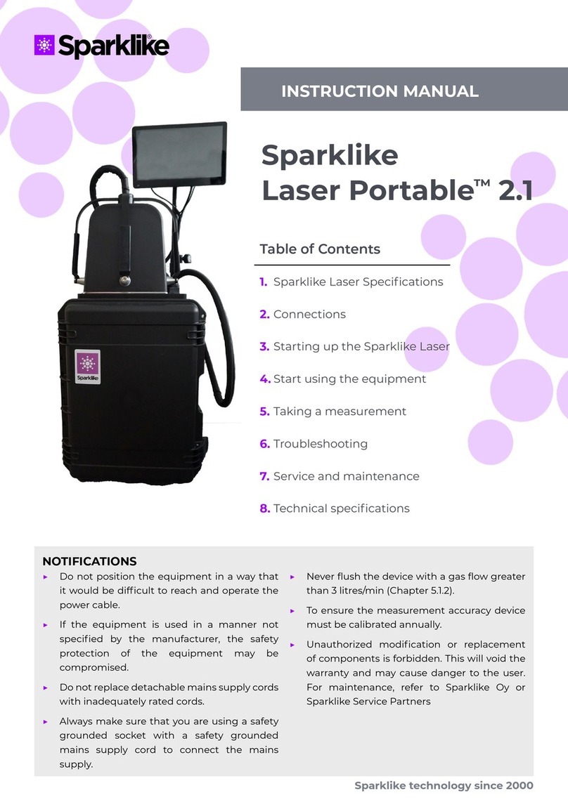
sparklike Laser Portable 2.1 User manual
sparklike
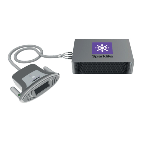
sparklike GasGlass User manual

sparklike
sparklike Handheld 3.0 User manual

sparklike
sparklike Handheld User manual

sparklike
sparklike Laser Portable 2.1 User manual

sparklike
sparklike Gasglass handheld User manual

sparklike
sparklike GASGLASS HANDHELD V2 User manual

sparklike
sparklike Handheld 3.0 User manual

sparklike
sparklike Handheld 3.0 User manual
sparklike
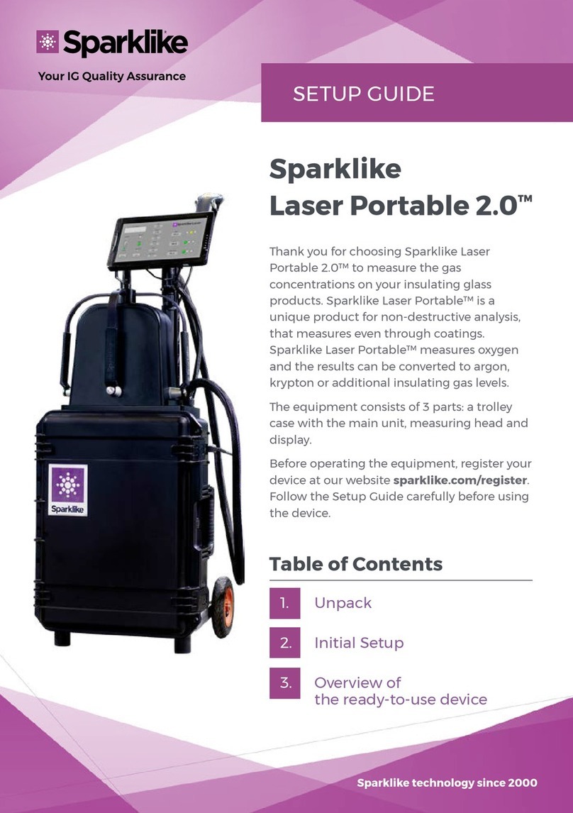
sparklike Laser Portable 2.0 User manual


