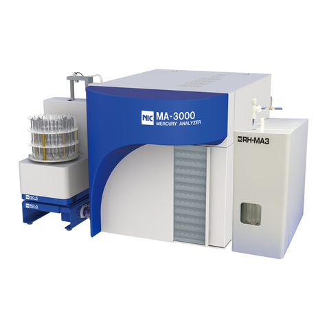
Nippon MA-3000 User manual

1
.
Inspection
i
No.
704-2010-01
MA-3000
Service Manual
Document No. NIC-704-2010-01 Date of Issue
Jan. 16, 2014
Management Dept.
Page 1/
MA-3000
SERVICE MANUAL
Nippon Instruments Corporation
Service Department
Date Written By Checked By Approved By
1st edition Jan. 15, 2014 Kotake Daito Noda

1
.
Inspection
ii
No.
704-2010-01
MA-3000
Service Manual Document No. NIC-704-2010-01 Date of Issue
Jan. 15, 2014
Management Dept.
Page 2/
Revision History
Ver.
Revision
Date Reason for Revision Written By
Approved By
01
Jan. 15,
2014 First edition issued Kotake Noda

1
.
Inspection
iii
No.
704-2010-01
FULL-AUTOMATIC HEAT-VAPORIZATION MERCURY ANALYZER
MERCURY MA-3000 SERVICE MANUAL
Contents
SERVICE MANUAL..............................................................................................................1
1.Inspection........................................................................................................................4
1.1. Removal of cabinet covers.....................................................................................5
1.2. Cell cleaning...........................................................................................................8
1.3. Replacement of joint.............................................................................................12
1.4. Dismounting the sample heating tube ..................................................................13
1.5. Mounting the sample heating tube .......................................................................15
1.6. Overall operation check of sample changer .........................................................18
1.7. Procedure for leak check......................................................................................23
1.8. Inspection.............................................................................................................28
2. Replacement work........................................................................................................29
2.1 Replacement procedure of H1 heater .......................................................................30
2.2 Adjustment procedure of H1 heater...........................................................................33
2.3 Replacement procedure for H2 heater......................................................................34
2.5 Replacement procedure of thermocouple for H3 heater ...........................................39
2.6 Replacement procedure of SSR................................................................................41
3. Sample changer and its relatives................................................................................44
3.1 Recovery procedure for the MA-3000 sample changer error ....................................44
3.2 Function check of each sensor..................................................................................47
3.3 Replacement procedure of boat taking Boat handling poker.....................................49
3.4 Adjustment of sample changer (Vertical axis, Y-axis)................................................52
3.5 Adjustment of sample changer (Horizontal axis, X-axis)...........................................55
3.6 Adjustment of sample changer (Lift axis) ..................................................................56
・ Replacement of lift motor.........................................................................................57
4. About high level pollution............................................................................................58


1
.
Inspection
1
No.
704-2010-01
Inspection
Since extensive improvement has been carried out for the MA-3000, its structure after the
improvement differs from that before the improvement.
Instruments with serial numbers 10740001 to 12740140 are referred to as the Version I type,
and those with serial numbers 13740141 and later are referred to as the Version II type for
convenience.
・List of time-change components for MA-3000
Sample heating tube MA-3 W139-1360-01 1
Mercury collection tube (gold nanoparticles) W139-1341-00 1
Teflon joint 6 mm dia. N-41663 1
Different diameter union tee 516165 1
*When the system has the option.
Different diameter union cross 516166
Teflon joint FLW-30-3U-S 1
Different diameter union elbow 3-4 FLW-30-4RUE3-S 1
Inlet O-ring P-022A DPN-P-022A-7075 1
In/out rod O-ring 24A DPN-P-024A-7075 1
Teflon tube (3 mm dia. ×2 mm dia.) S1037-0202-00 60 cm
Activated carbon case (for exhaust) W139-1120-01 1 set
MA-3000 sample boat set (10 pcs.) S1106-6100-00 1 set

1
.
Inspection
2
No.
704-2010-01
1.1.
Removal of cabinet covers
①Top cover
・Version I type
With the instrument turned off, remove the
ring latches and remove the top cover.
・Version II type
With the instrument turned off, remove the
ring latches.
* The M3 screws in the upper part of the
rear are for transportation. Remove them
after installation.

1
.
Inspection
3
No.
704-2010-01
②Removal of right side panel
・Type A or B
Remove the fixing screws for
transportation.
・Type C
Remove the knurled screw in the rear.
Remove the two knurled screws and
remove the side panel.
Remove the M3 screw fixing the right side
panel, and remove the side panel.

1
.
Inspection
4
No.
704-2010-01
③Removal of left side panel
・Type A or B
Remove the fixing screws for
transportation.
・Type C
Remove the knurled screw in the rear.
Remove the two knurled screws and
remove the side panel.
Remove the M3 screw fixing the left
side panel, and remove the side panel.

1
.
Inspection
5
No.
704-2010-01
1.2.
Cell cleaning
(1) Preparation of components
(2) Removal
Remove the top cover and remove the cover of the optical system from its case. Then,
remove the cell retainers, loosen the joint and the screws fixing the optical system,
and remove the cell unit.
MA-3000 (Version I type) MA-3000 (Version II type)
* If the 1 mm cell, branch pipe or O-ring has a crease or breakage, replace it.
If not replaced, it will cause a leak.
No.
Name Comp. No. Qty Remark
1 Phillips screwdriver (02) - 1 Tool
2 Phillips screwdriver (01) 1 Accessory
3 Coin 1 Tool
4 Beaker (500 mL) 1 For cleaning
5 10% nitric acid 500 mL For cleaning
6 Distilled water 1 L For cleaning
7 Alcohol (ethanol etc.) 100 mL For cleaning
8 Cotton waste 1 box For cleaning
9 Rubber glove 1 set For cleaning

1
.
Inspection
6
No.
704-2010-01
(3) Disassembly of component
Disassemble the cell unit and divide it into metal components and other.
* When it is impossible to remove the cell window, it can be removed by soaking it in
water. Do not give a strong shock.
(4) Cleaning of components
Clean up the metal components using alcohol, and wipe them.
Wash the other parts using neutral detergent and nitric acid.
Wash them using neutral detergent for 30 minutes with ultrasonic washer, or soak
for five hours without it. Discard cleaning fluid, rinse the components well using
distilled water and dry them.
Rinse the components well, and wash with nitric acid as well. Then rinse well the
items with distilled water and dry them.

1
.
Inspection
7
No.
704-2010-01
(5) Reassembly
・Version I type ・Version II type
*The order of the packing and glass are different in the Version I type and Version II type.
Version I type ・Version II type
Reassemble the cell unit. (Take care not to mistake the position packing(s) and O-
ring(s).)
Keep in mind that the screw will break if the connection of the 200-mm cell
and the 1-mm cell is fastened too much tightly. Fixing of components
(6) Attach the cell unit, tighten the screws fixing the optical system and finally retighten
the joint.
(7) After the power is turned on and all heaters are stabilized, adjust the voltages for the
optical system.
(It takes at least one hour to stabilize the temperature in the instrument.)

1
.
Inspection
8
No.
704-2010-01
(8) Gain adjustment*
(9) Make the gain adjustment only when the shift of the voltage is large after
replacing cells, and cleaning photoelectric tubes, lens and half-mirrors.
Version I type
Adjust SIG1, SIG2 and REF to about 3 using
the trimmers 20 minutes after switching on the
power supply. And then tune them to 3.0 +/-0.2
1 hour or more after.
*Adjustment of them if this is not possible, then change the resistance.
Turn off the power and unplug the connector of the optical system.
Remove the screws that secure the phototube of SIG2 and SIG1.
Remove the board and change the resistance.
If you wish to double its current
value, replace the resistor with the
twice resistance-value .

1
.
Inspection
9
No.
704-2010-01
Version II type.
* Use the automatic gain adjustment function for the Version II type.
・Before the adjustment, record the constants of the current offset information and gain
information.
・Push the “AUTO” button to make the automatic gain adjustment.
・If the difference from the constant before the alteration is abnormally large after the
automatic adjustment is made, make an adjustment again. If the difference from the
original constant is 50 or more, the adjustment will be regarded as no good.
③

1
.
Inspection
10
No.
704-2010-01
1.3.
Replacement of joint
(1) Preparation of components
(2) If the joint connected to a Teflon tube is tightened too strongly, it will be damaged. If
a cap nut, especially one made of stainless steel, is tightened sl, the thread may be
damaged and an accident in which a leak does not stop may occur. (The photographs
below show defective components.)
(3) Tightening Procedure
In the case of a joint and a Teflon tube, tighten them manually and then tighten them
furthermore by one turn.
In the case of a joint and a glass tube, tighten them manually and then tighten them
furthermore by a 1/6 turn.
(4) Loosen a stainless steel cap nut without removing it when disconnecting a pipe. If it
is removed, attach it while keeping the joint parallel to the cap and making sure of the
engaging of the screws.
(5) To tighten the loosened 6 mm dia. joint (connection of the collection tube and the
sample heating tube), tighten it with the one side fixed using long-nose pliers.
No.
Name Comp. No. Qty Remark
①
Joint - 1 Tool
②
Long-nose pliers 2 Tool
③
Monkey wrench (small) 1 Tool

1
.
Inspection
11
No.
704-2010-01
1.4.
Dismounting the sample heating tube
Warning Carry out maintenance of the heated sections only after the
power switch has been turned OFF and the heater has cooled
down to room temperature or it could result in burns.
Remove the top cover and open the front
cover. (Locked when the power is ON)
Open the front cover and turn ON the power
of the MA-3000.
Turn OFF the MA-3000 after the sample
changer operates, and the Z axis moves
towards you and stopped.
Loosen the Teflon joint at the sample inlet.
Unscrew 4 knurled screws holding the
sample heating tube retainer and the pipe
heater cover, and remove the retainer and
the cover.
Loosen the joint connecting the mercury
collection tube and the cell.
Loosen 2 box nuts of the reducing T joint on
the side of the mercury collection tube and
on the side of the detector to remove the
joint.
*
The joint would be a cross joint in the case
an optional unit is supplied.

1
.
Inspection
12
No.
704-2010-01
Loosen the 4 panel fasteners on the inlet
shaft on both the left and right sides with a
Phillips screw driver (No.2) and open the
door to the right.
Remove the 3 screws that fix the sample
inlet.
Remove the sample heating tube.
Remove the 3 flat head screws on the
sample inlet and slowly turn sample heating
tube and mercury collecting tube to pull
them out.
Unscrew 3 screws with a hex wrench and
pull out the sample heating tube. Also
remove the box nuts of the Teflon joint.

1
.
Inspection
13
No.
704-2010-01
1.5.
Mounting the sample heating tube
Make sure that the O-ring is not damaged
when assembling the sample inlet.
Place the O-ring in the center of the sample
inlet retainer and pass the branch tube
through the sample inlet ring.
Do not confuse the head and tail of the ring.
Install the sample heating tube in the
retainer.
Insert the tube and tighten the screws.
(Tighten the 3 screws gradually in an
alternative manner until there is no
clearance.)
Install the Teflon joint and the mercury
collection tube to the sample heating tube.
Disassemble the Teflon joint, pass the
sample heating tube through the box nut,
washer, O-ring and joint in this order and
tighten the nut.
Here, do not insert the joint too deep so that
the position can be easily adjusted later.
* The thread on the Teflon joint is easily
damaged. Ensure to verify that the nut
turns smoothly. If the box nut does not
correctly engage the thread, it could result
in leaking.
Wipe the outside of the sample heating tube
and the mercury collection tube with alcohol.

1
.
Inspection
14
No.
704-2010-01
Insert the sample heating tube.
Slowly insert the sample heating tube into
the sample inlet while twisting it gently to the
left and right.
* Pushing it too forcefully could result in the
heater being deformed.
Pass the mercury collection tube through the
H3 heater and push it until the sample inlet
touches the reducing joint.
Adjust the position of the mercury collection
tube. Align the end of the heater and the
dent of the mercury collection tube. Adjust
the position by adjusting the insertion depth
of the Teflon joint.
Tighten the Teflon joint securely. In particular,
the reducing joint must be tightened lightly
with a hand at first and then re-tightened with
a wrench by about ½ turn.
* The joint may be broken if excessively
tightened.
Fix the mounting piece of the sample heating
tube in place.
Tighten the screws with the supplied hex
wrench.
Close the door of the sample inlet shaft.
Gradually tighten the panel fasteners with a
Phillips driver (No.2). Tighten all of the 4
screws lightly and then the re-tighten them
little by little.

1
.
Inspection
15
No.
704-2010-01
⑪Connect the elbow joint to the branch pipe
on the sample inlet.
⑫Install the pipe heater cover and sample
heater tube retainer. Close the front cover
and install the top cover.
⑬Turn ON the power of the MA-3000 and
perform the check of flow path to make sure
that there is no leak.

1
.
Inspection
16
No.
704-2010-01
1. .
Check of sample changer
(1) Select [run] - [maintenance] on the menu bar to open the “Maintenance” screen, and
select the “BC” tab. Then, click BC ADJUST and make the operation check of the sample
changer.
It is possible to specify the tray number and boat number at (1) and (2), respectively.
*
A number can be changed only when it is displayed in black.
Items (3) and (4) show operation to be carried out when (5) or (6) is selected.
Item (5) is used for operation in the direction to insert a boat.
Item (6) is used for operation in the direction to return a boat.
①Ready state
Put a boat on Tray No. 1 and set it to the
MA-3000.
①
②
③
④
⑤
⑥
Other manuals for MA-3000
1
Table of contents
Other Nippon Measuring Instrument manuals
Nippon
Nippon RA-4500 User manual
Nippon
Nippon EMP-3 User manual
Nippon
Nippon WA-5A User manual
Nippon
Nippon MA-3 Solo User manual
Nippon
Nippon Hi-Lutor User manual
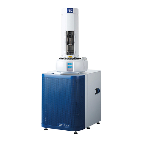
Nippon
Nippon Mercury/PE-1 User manual
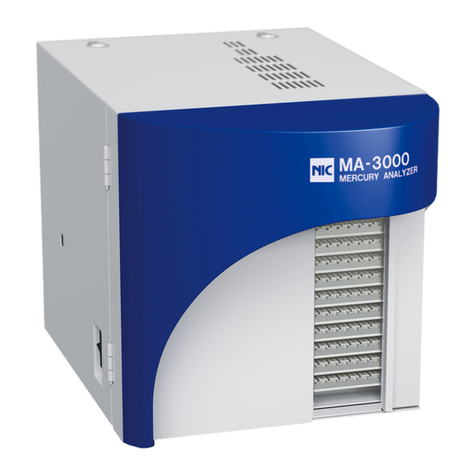
Nippon
Nippon MA-3000 User manual

Nippon
Nippon EMP-3 User manual
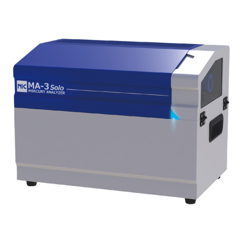
Nippon
Nippon AQUA User manual

Nippon
Nippon MA-3 Solo User manual
Popular Measuring Instrument manuals by other brands
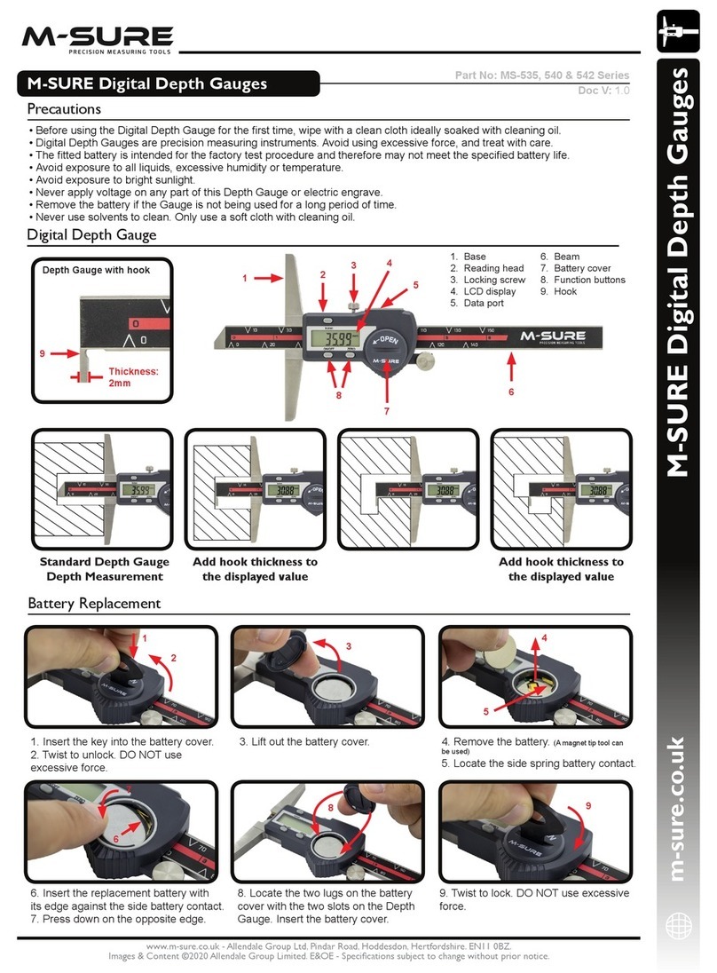
M-Sure
M-Sure MS-535 Series quick start guide
Komshine
Komshine KFI-40 user manual
TDE Instruments
TDE Instruments Digalox DPM72-MPPV-USB instruction manual

agratronix
agratronix MT-PRO+ Operator's manual

ATS
ATS ATS-FM-M Instructional manual

BEG
BEG LUXOMAT Indoor 180N-R/2W-UK Installation and operating instruction
