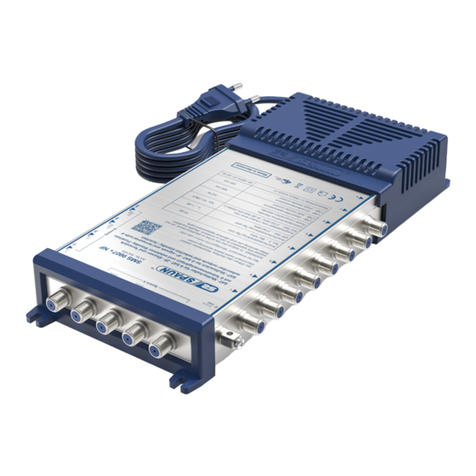
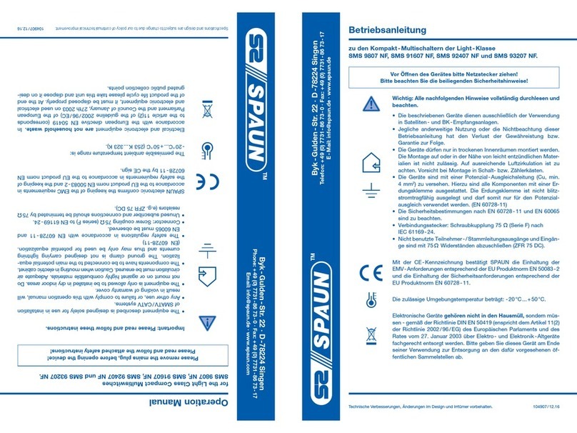
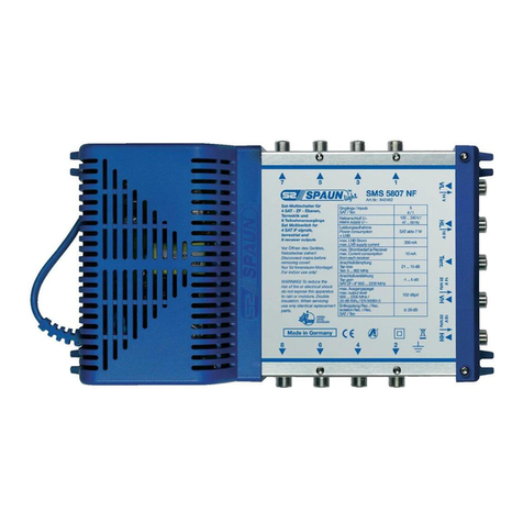
SPAUN SMS 607 Plus NF User manual

Unterer Dammweg 6/1 · D-78050 VS-Villingen
Phone: +49 (0) 7721 40 219 - 0 · Fax: +49 (0)7721 40 219 - 50
05.22
Betriebsanleitung
zu den Kompakt-Multischaltern SMS 5607+ NF, SMS 5807+ NF,
SMS 51207+ NF und SMS 51607+ NF.
Vor Öffnen des Gerätes bitte Netzstecker ziehen!
Bitte beachten Sie die beiliegenden Sicherheitshinweise!
Wichtig: Alle nachfolgenden Hinweise vollständig lesen und beachten.
Das Gerät dientausschließlich der Verwendung in Satelliten- und
Terrestrischen- Empfangsanlagen. Jegliche anderweitige Nutzung ist
nicht gestattet. Das Gerät darf ausschließlich von sachverständigen
Personen installiert, gewartet, repariert und in Betrieb genommen
werden (siehe EN 60065).
Das Gerät darf nur in trockenen Innenräumen montiert werden.
Die Montage auf,oder in der Nähe von leicht entzündlichen Mater-
ialien, ist nicht zulässig. Auf ausreichende Luftzirkulation ist zu
achten. Vorsicht bei Montage in Schalt- bzw. Zählerkästen.
Das Teilnehmernetz muss gemäß DIN EN 60728-11 vorschrifts-
mäßig geerdet sein und bleiben, auch wenn das Gerät ausgebaut
wird. Verwenden Sie hierzu falls vorhanden den Erdungsanschluss
des Geräts bzw. die beiliegende Erdungsklemme (4 mm2). Die
Sicherheitsbestimmungen nach EN 60728- 11 und EN 60065 sind zu
beachten.
Nicht benutzte Teilnehmeranschlüsse und
ggf. Stammleitungsein- und Ausgänge sind mit
75 ΩWiderständen abzuschließen (ZFR 75 DC).
Die zulässige Umgebungstemperatur beträgt: -20 …+ 55° C.
Elektronische Geräte gehören nicht in den Hausmüll, sondern müs-
sen - gemäß der Richtlinie DIN EN 50419 (entspricht dem Artikel 11(2)
der Richtlinie 2002/ 96/ EG) des Europäischen Parlaments und des
Rates vom 27. Januar 2003 über Elektro- und Elektronik -Altgeräte
fachgerecht entsorgt werden. Bitte geben Sie dieses Gerät am Ende
seiner Verwendung zur Entsorgung an den dafür vorgesehenen öf-
fentlichen Sammelstellen ab.
Technische Änderungen und Irrtümer vorbehalten.
Hiermit erklärt die Dura-Sat GmbH & Co. KG, dass der
Funkanlagentyp Multischalter SMS den Richtlinien 2014/53/EU
entspricht. Der vollständige Text der EU-Konformitätserklärung
ist unter der folgenden Internetadresse verfügbar:
https://www.spaun.com/download

Stromversorgung
Die Kompakt-Multischalter sind mit einem kurzschlussfesten Schaltnetzteil ausgestattet.
U~: 90- 240V /47 -63 Hz.
Standby-Funktion
Die Multischalter verfügen über eine Standby- Funktion. Die Satelliten- ZF- Verstärkerstufen und die
Stromversorgungen zum LNB sind abgeschaltet. Ist ein Receiver oder Antennenmessgerät mit einge-
schalteter LNB- Stromversorgung an einen Teilnehmerausgang der Multischalter angeschlossen, schaltet
dieser automatisch auf Normalbetrieb.
Stromversorgung LNB
Durch einen integrierten 22 kHz-Generator sowohl für Quattro- als auch für QUAD-LNB geeignet.
Der Fernspeisestrom darf maximal 500 mA betragen.
Eingangspegel
Terrestrik
1. Die Verteilung der Terrestrik erfolgt passiv.
2. Die Verteildämpfung pro Teilnehmer beträgt:
Terrestrische Antennensignale müssen dem breitbandigen Eingang der Multischalter zur Vermeidung von
Störungen selektiv zugeführt werden.
Der Frequenzbereich geht von 5 …862 MHz; die Multischalter sind somit rückwegtauglich.
SAT -ZF-Verteilung
Der maximale Eingangspegel beträgt bei Transpondervollbelegung typisch:
SMS 5607+ NF SMS 5807+ NF SMS 51207+ NF SMS 51607+ NF
19 dB ± 1 dB 19 dB ± 1 dB 23 dB ± 1 dB 23 dB ± 1 dB
SMS 5607+ NF SMS 5807+ NF SMS 51207+ NF SMS 51607+ NF
90 dBµV 90 dBµV 92 dBµV 92 dBµV

Technische Daten
Modell
Art. Nr.
SMS 5607+ NF
815014
SMS 5807+ NF
842462
SMS 51207+ NF
842463
SMS 51607+ NF
842464
Teilnehmerausgänge 6 8 12 16
Eingänge
SAT/Terrestrik
5
4/ 1
Anschlussdämpfung
Terrestrik 5… 862 MHz 19 dB ± 1 dB 19 dB ± 1 dB 23 dB ± 1 dB 23 dB ± 1 dB
Anschlussdämpfung
SAT-ZF 950 …2200 MHz 4… 1 dB ± 1 dB
Ausgangspegel max.
950… 2200 MHz
35 dB IMA3/EN 60728 -3
typ. 102 dBµV
Entkopplung
Receiver/ Receiver
Terrestrik/ SAT
typ. 30 dB
Netzanschluss U~ 90- 240V /47 -63 Hz
Leistungsaufnahme
Standby typ. 0,1 W
LNB- Strom max. 500 mA
Strombedarf je Receiver 38 mA
Leistungsaufnahme inkl.
ECO LNB Last mit 100 mA typ. 2,4 W
Umgebungstemperatur -20 …+ 55° C
Abmessungen in mm 208 x 136 x 43 208 x 136 x 43 290 x 136 x 43 290 x 136 x 43

SMS 51607+ NF
8 x ASE 5 F
GND
8 x ASE 5 F
Anwendungsbeispiel
Application diagram
ZFR 75 DC

Anwendungsbeispiel
Application diagram
SMS 5807+ NF
3 x ASE 5 F
GND
4 x ASE 5 F
ZFR 75 DC

Unterer Dammweg 6/1 · D-78050 VS-Villingen
Phone: +49 (0) 7721 40 219 - 0 · Fax: + 49 (0)7721 40 219 - 50
05.22
Operation Manual
for the Compact Multiswitches SMS 5607+ NF, SMS 5807+ NF,
SMS 51207+ NF and SMS 51607+ NF.
Hereby, Dura-Sat GmbH & Co.KG declares that the radio equipment
type multiswitch SMS is in compliance with Directives 2014/53/EU.
The full text of the EU declaration of conformity is available at the
following internet address:
https://www.spaun.com/download
Remove mains cable before opening the device!
Please follow the safety instructions enclosed!
Important: Please read through these instructions thoroughly and follow them.
Unused subscriber ports and if applicable
trunk line inputs and outputs must be terminated
with 75 Ωresistors (ZFR 75 DC).
The device is only intended for use in satellite and terrestrial receiver
systems. Any other use is prohibited. The device must be installed,
maintained, repaired and put into operation by competent people
(see EN 60065).
The device must be installed indoors, in dry rooms exclusively.
Installation on or in close proximity to highly flammable materials is
prohibited. Ensure sufficient air circulation. Take care when installing
in switch cabinets or meter cabinets.
The device and the peripheral distribution devices must be earthed
in accordance with the provisions of EN 60728-11 and must remain
earthed even when the device is disassembled. For this purpose, if
available use the earthing connection of the device or the earthing ter-
minal enclosed (4 mm2). Observe the safety regulations in accordance
with EN 60728- 11 and EN 60065.
The permissible ambient temperature range is: -20 …+ 55° C.
Electronic devices are not household waste but rather must be
disposed of properly in accordance with directive DIN EN 50419
(reflects article 11(2) of directive 2002 / 96 / EC) of the European
Parliament and the Council of 27th January 2003 regarding used
electrical and electronic devices. At the end of the product life cycle
please take this device and dispose it via designated public collection
points.
Technical data subject to change without notice. Errors excepted.

Power Supply
The compact multiswitches are equipped with an switched-mode power supply.
U~: 90- 240V /47 -63 Hz.
Standby Mode
The multiswitches have a standby mode. The satellite IF amplifier stages and the supply for the LNB are
switched off. If a receiver or antenna test equipment with LNB power supply is connected to a subscriber
output of the multiswitch, then this automatically switches to normal operation mode.
Power Supply to LNB
Integrated 22 kHz generator suitable for Quattro- and QUAD LNB.
The maximum permissible current is 500mA.
Input Level
Terrestrial
The terrestrial signals are distributed passively. As the frequency range is from 5 …862 MHz the multi-
switch is return path capable.
Subscriber Tap Loss
SMS 607+ NF SMS 5807+ NF SMS 51207+ NF SMS 51607+ NF
19 dB ± 1 dB 19 dB ± 1 dB 23 dB ± 1 dB 23 dB ± 1 dB
SMS 5607+ NF SMS 5807+ NF SMS 51207+ NF SMS 51607+ NF
90 dBµV 90 dBµV 92 dBµV 92 dBµV
Terrestrial antenna signals should be fed selectively to the multiswitch in order to avoid malfunctions.
SAT IF Distribution
The maximum input level is typically at full transponder load:

Modell
Art. Nr.
SMS 5607+ NF
815014
SMS 5807+ NF
842462
SMS 51207+ NF
842463
SMS 51607+ NF
842464
Subscriber outputs 6 8 12 16
Inputs
SAT/terrestiral
5
4/ 1
Tap loss
Terrestrial 5… 862 MHz 19 dB ± 1 dB 19 dB ± 1 dB 23 dB ± 1 dB 23 dB ± 1 dB
Tap attenuation
SAT-ZF 950 …2200 MHz 4… 1 dB ± 1 dB
Output level max.
950… 2200 MHz
35 dB IMA3/EN 60728 -3
typ. 102 dBµV
Isolation
Receiver/ receiver
Terrestrial/ SAT
typ. 30 dB
Mains supply U~ 90- 240V /47 -63 Hz
Input power
Standby typ. 0,1 W
LNB supply current max. 500 mA
Current consumption
from each receiver 38 mA
Power consumption incl.
ECO LNB load with 100 mA typ. 2,4 W
Ambient temperature -20 …+ 55° C
Dimensions (mm) 208 x 136 x 43 208 x 136 x 43 290 x 136 x 43 290 x 136 x 43
Technical data

SMS 51607+ NF
8 x ASE 5 F
GND
8 x ASE 5 F
Anwendungsbeispiel
Application diagram
ZFR 75 DC

Anwendungsbeispiel
Application diagram
SMS 5807+ NF
3 x ASE 5 F
GND
4 x ASE 5 F
ZFR 75 DC
This manual suits for next models
4
Table of contents
Languages:
Other SPAUN Switch manuals
