SPC Thermatile Ten-Twelve User manual

Thermatile Ten-Twelve
Radiant Panels
Installation instructions

2IOM 53, Issue 13 - Thermatile TEN-TWELVE
Contents Page
1|General 3
1.1 |Description 3
1.2 |Receipt and Preparation 3
1.3 |Storage and Handling 4
1.4 |Dimensional Data 4
1.5 |Technical Data 4
2|Installation 5
2.1 |Ceiling Grid 5
2.2 |Free Hanging 5
2.3 |Plasterboard 6
2.4 |Multiple Panels 7
2.5 |Wire/Rod Hanging Requirements 8
2.6 |Non-standard Applications 9
2.7 |Electrical Connections 9
2.8 |Mounting Height 10
3|Operation 11
3.1 |Cooling Applications 11
3.2 |Sensors 11
3.3 |Fault Finding 11
4|Maintenance 11
5|Appendix 12
5.1 |Appendix 1 - Wall-mounted installation 12
5.2 |Appendix 2 - Plastic ball guard 14
5.3 |Appendix 3 - Site Handling 15
5.4 |Appendix 4 - Bracket Positions 16

3IOM 53, Issue 13 - Thermatile TEN-TWELVE
1. General
1.1 Description
The SPC Thermatile TEN-TWELVE panels are
manufactured from a unique aluminium sandwich
panel that is both structurally rigid and an
excellent conductor of heat.
The TEN panel incorporates a bespoke cartridge
element bonded to the back of the panel through
which 10mm copper tubes run; connections are
10mm, the tubes are based on ‘D’ technology with
attened bases for increased contact. The TWELVE
panel uses the same construction but 12mm
copper pipes. The TEN panel is most usually used
for individual panels while the TWELVE is most
usually used on long continuous runs. The TWELVE
panels terminate in specially designed 22mm
manifold pieces.
Panels are suitable for laying in false ceiling grids
between T bars, free hanging or for installation
into plasterboard ceilings. Panels for grids and
plasterboard would normally be supplied with
a pre-installed insulating pad to minimise heat
loss into the void. Panels for such applications
can be supplied without the insulation but it is
recommended that the installer provides their
own insulation in this instance. Panels intended
for installation in plasterboard will be supplied
with edge extrusions for plasterboard xing.
Panels can also be supplied with special brackets
for wall rather than ceiling mounting. Free hanging
panels would normally be supplied without
insulation and may be used for cooling as well
as heating. Such panels can be supplied with
extruded aluminium trim to cover the cut edges
which adds around 10mm to the dimensions
of the panels and makes them unsuitable for
installation in grids.
Panels are supplied with xing brackets for
wire hangers as standard though threaded rod
adaptors are available to order. Panels may be
supplied with suspension kits, control kits and/or
exible connection hoses. The hose for the TEN
panels would normally be 10mm to 15mm push-t
and the TWELVE hoses 22mm to 22mm push-t
and 750mm long (hoses with compression ttings
are also available on request). Shorter hoses for
interconnecting TWELVE panels are supplied with
22mm ttings (push-t by default) on both ends. A
range of dierent hose ttings and lengths may be
supplied.
While bespoke sizes are possible the standard
panel width is 595mm and standard panels
lengths are 590, 1190, 1790, 2390,2990 and
3590mm. Maximum depth over the panel and
pipes is less than 25mm; insulation, if tted, is
additional to this. Connections will extend
beyond 25mm.
1.2 Receipt and Preparation
Panels are supplied suitably packed with an
additional plastic lm applied to the nished
lower surface. This lm should remain on until
such time as the panels are to be tted and then
peeled away. Cleaning of the underside of the
panel can be undertaken using a wet or dry cloth
but abrasives and staining cleaning agents must
not be used. If the protective lm is removed after
hanging care must be taken to prevent damaging
the brackets and anchors.

4IOM 53, Issue 13 - Thermatile TEN-TWELVE
1.3 Storage and Handling
Panels are packed in cardboard cartons
bearing the SPC works order number, model
reference and site references where appropriate.
Installation, operation and maintenance instructs
are also supplied along with any special drawings
or instructions required for the project. On receipt
check that all details are correct to the schedule
and report any damage or missing parts to the
carrier and SPC immediately.
It is recommended that the panels remain in the
packaging until they are required. When handling
panels safety gloves must be worn.
1.4 Dimensional Data
Panels can be supplied in bespoke sizes but the
approximate sizes and weights of standard panels
are as shown in the table below:
Nominal Panel Size 600x600 1200x600 1800x600 2400x600 3000x600 3600x600
Outside dimensions (mm) 590x595 1190x595 1790x595 2390x595 2990x595 3590x595
Approximate dry weight (kg) 3.2 6.4 9.6 12.8 16.0 19.2
Internal volume (l) 0.2 0.3 0.6 0.8 1.0 1.3
Approximate wet weight (kg) 3.4 6.7 10.2 13.6 17.1 20.5
1.5 Technical Data
Panel Type Ten Twelve
Tube O/D (mm) 10.0 12.0
Tube wall thickness (mm) 0.35 0.5
Underside (visible) skin 0.7mm painted aluminium 0.7mm painted aluminium
Upper skin 0.5mm primered aluminium 0.5mm primered aluminium
Core Aluminium (honeycomb or equivalent) Aluminium (honeycomb or equivalent)
Panel thickness 5.0/5.5mm 5.0/5.5mm
Tube holders Cartridge panel Cartridge panel
Maximum working pressure 10 bar 10 bar
Maximum working temperature 85°C 85°C

5IOM 53, Issue 13 - Thermatile TEN-TWELVE
2. Installation
2.1 Ceiling Grid
Single panels are typically placed into a T-bar
type ceiling grid based on a 600mm square grid
pattern. While the panels will rest unsupported
in the grid they must be xed to the ceiling for
safety reasons. Panels will be supplied, by default,
with brackets suitable for wiring hanging, if rod
hanging is preferred then adaptor brackets need
to be ordered, Gripple type wire suspension kits
are recommended. The wires or rods must hang
vertically between the brackets and ceiling as
the brackets/rivets are not suitable for signicant
lateral loads.
Panels may be supplied with connecting hoses
which will be either 15mm or 22mm and either
push-t or compression type. For connecting
panel to panel shorter interconnecting hoses may
be supplied with 10mm to 10mm connections
or 22mm to 22mm connections in push-t or
compression. Push-t connectors rely on a rubber
O ring for sealing and it is important that the ends
of the pipework are rounded and led (deburred)
before the push-t hose is attached to ensure a
damage free seal.
2.2 Free Hanging
Panels must be independently supported from the
ceiling/sot using either wire or rod hangers. The
panels are supplied, as standard, with the requisite
number of standard wire hanging brackets, if rod
hangers are to be used then suitable brackets
would need to be ordered to adapt the standard
wire hanger. Anchors of a suitable type to match
the ceiling fabric must be tted in the ceiling
directly above the brackets attached to the panels.
Connecting and inter-connecting hoses may
be supplied with the panels and their use and
installation should be as above.
Panels may be supplied with extruded aluminium
trim around the perimeter. Such panels are
suitable for hanging via wire systems from the
trim itself rather than via brackets. If insulation
is tted to the back of the panels this will readily
deform to allow tting of the wire hanging hook. If
rod fasteners are used instead of wire fasteners, it
should be stated on the order and larger diameter
holes will be drilled in the trim. If rod fasteners
are not identied at order stage, the trim can be
drilled on site to suit the diameter of the rod.

6IOM 53, Issue 13 - Thermatile TEN-TWELVE
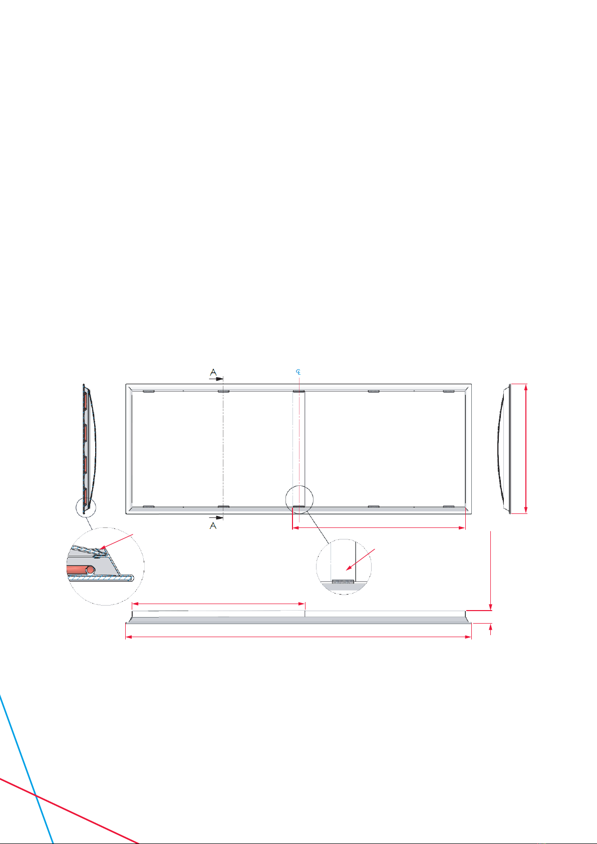
2.3 Plasterboard
Panels are available for plasterboard ceilings and
are supplied with a special frame. The frame is an
extrusion which ts around the perimeter of the
panel. Fixing screws are tightened through the
frame into wooden battens in the ceiling.
The drawing below shows the steps to be taken in
order to properly mount plasterboard panels; the
primary support is via the hanging wires and the
screws into the battens provide additional support
and ensure that the frame sits level. The drawing is
intended to give information regarding the method
of installation; the actual installation will vary in
terms of number and position of xings.
Thermatile Fitting Instruction For Plasterboard Ceiling
Panel Length Ceiling Aperture Width Ceiling Aperture Length
590 605 600
1190 605 1200
1790 605 1800
2390 605 2400
2990 605 3000
3590 605 3600
Stage 1
• Cut aperture in plasterboard (see table
for size).
• Fit suitable wooden batten around perimeter
in ceiling void.
• Attach hanging wires to anchor points above
(by others).
Stage 2
• Attach wires to wire hanging brackets and
connect push t hoses for ow and return.
Stage 3
• Push panel up ush with ceiling and screw
through plasterboard to batten

7IOM 53, Issue 13 - Thermatile TEN-TWELVE
2.4 Multiple Panels
When panels are intended for installation in
continuous runs they may be supplied with
interconnecting hoses. Due to the high owrates
associated with continuous runs they will be from
12mm tube i.e. the TWELVE type panel.
The gure below shows a two panel run with
interconnecting hoses. Runs with greater numbers
of panels will have multiple panels interconnected.
The longer hoses are for connection to the main
ow and return piping.
Note: Interconnecting hoses need to be bent
through 180º as shown so as to connect pairs
of connections facing in the same direction.
No other arrangement of interconnection is
allowed and will be impossible with the hoses
supplied.
Figure 2. Example of multiple panel runs
Figure 1. Plasterboard hanging
SECTION VIEW
Plaster Board
Thermatile
Frame
Wooden Batten

8IOM 53, Issue 13 - Thermatile TEN-TWELVE
2.5 Wire/Rod Hanging Requirements
The panels are supplied as standard with the
necessary quantity of xing brackets fastened to
the rear of the panel. The standard bracket suits
wire hanging but adaptors are available to make
the brackets suitable for hanging via threaded rod.
Irrespective of the hanging type, wire or rod, the
hangers must be vertical and anchored to the
ceiling directly above the bracket. The brackets are
not designed to be suitable for signicant lateral
forces.
When installing panels they must not be hung
from some of the brackets unsupported. All of
the brackets must be properly secured before
the support is released. This support could be a
tter or tters or, if available, a scissor lift or other
mechanical means.
Figure 3. Incorrect and correct hanging method
Figure 4. Panels must be supported on all brackets
(scissor lift etc useful for large panels)

9IOM 53, Issue 13 - Thermatile TEN-TWELVE
V/A = VALVE/ACTUATOR, CAN BE 2 PORT, 3 PORT ON/OFF OR MODULATING
S = SENSOR, POSITIONED IN A REPRESENTATIVE POSITION WITHIN THE ZONE
C = CONTROLLER, REACTS TO SENSED TEMPERATURE TO POWER VALVE ACTUATOR
V/A
C
S
S
ZONE 2
PANELS
ZONE 1
PANELS
C
V/A
RETURN
FLOW
2.6 Non-standard Applications
Panels may be supplied for other than ceiling
mounting. Panels can be tted vertically to walls
or at an angle from the wall at high level. In this
instance the panels will be supplied with the
necessary support struts and hanging brackets.
Such installations are normally bespoke and tting
instructions will be separately supplied or must be
requested from SPC.
2.7 Electrical Connections
There are no electrical connections to the panels
themselves. The arrangement of panels will
normally be in zones and these will be controlled
by valves which will require electrical power and
control wiring. The schematic is an example
of how the panels may be controlled; it is not
representative of the panels themselves.
Figure 5. Control example
10 IOM 53, Issue 13 - Thermatile TEN-TWELVE
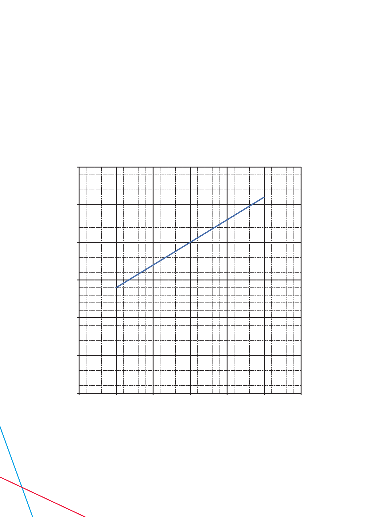
2.8 Mounting height
The chart showing minimum mounting heights
recommends the minimum height that the
panels should be mounted at, from the ground,
as a function of the water temperature in order
to prevent any discomfort occurring as a result
of asymmetric radiation. The chart is for static
occupancy; if occupants are moving around the
space then comfort can be ensured at higher
water temperatures or lower mounting heights.
0
0.5
1
1.5
2
2.5
3
30 40 50 60 70 80 90
Figure 6. Mounting heights
Minimum Mounting Height (m)
Mean Water Temperature (ºC)
Minimum Mounting Height Againt Mean Water
Temperature For Static Occupancy Comfort (ISO 7730)

11IOM 53, Issue 13 - Thermatile TEN-TWELVE
3. Operation
Ensure that the panels are piped together and
into the heating (cooling) system as required
by the application. Manual and or automatic air
vents should be tted at high points in the piping
systems. Ensure that all manual valves are opened
and allow uid to circulate through the heating
system. Open air vents to ensure that there is no
air trapped; close manual vents as soon as water is
released.
Zone valves should open and close in response
to the sensed room or zone temperature and
sensors should be positioned in representative
position within the space to achieve optimum
comfort.
3.1 Cooling Applications
When chilled water is used it is important that its
temperature is not less than the dewpoint of the
air in the space; In this way the panels will not
sweat. The temperature of the chilled water must
be controlled in response to the humidity in the
space and/or condensation sensors must be tted.
Note that the pipework to and from the panels will
also sweat and should be insulated/vapour sealed
wherever possible.
3.2 Sensors
For radiant systems black bulb sensors are
often used as they give a better indication of the
eective temperature in the space. If standard
air temperature sensors are used then allowance
needs to be made for the radiant eect – setpoints
can be a couple of degrees lower in heating mode
and higher in cooling mode.
3.2 Fault Finding
Fault Remedy
Air in system Open vent plug(s)
Low water temperature in heating mode Check operation of boiler and mixing valves
High water temperature in cooling mode Check operation of chiller and mixing valves
Low water ow rate Check operation of pump and diverting valves
Valves closed Check valve settings
4. Maintenance
Radiant panels are largely maintenance free. The
surface of the panel can be cleaned using a dry
cloth or non-abrasive/corrosive detergents; if
unsure rst try cleaning uid on a small area of the
panel.
The waterways consist of copper pipes and exible
hoses will normally be EPDM rubber, any ushing
undertaken or inhibitors used need to be suitable
for use with these materials.

12 IOM 53, Issue 13 - Thermatile TEN-TWELVE
5. Appendix
5.1 Appendix 1 - Wall-mounted installation
Below are examples of typical wall-mounted
applications where the panels are mounted at
an angle from the wall. SPC supply comprises
the panels themselves with special wall-mounted
brackets riveted to the back towards the bottom
of the panel. These brackets are notched at an
angle to suit the corresponding wall brackets also
supplied by SPC.
The installer will need to x unistrut or equivalent
to the walls at the centres indicated and attach
the wall brackets to the unistrut via captive spring
nuts and bolts. For angled panels the top of the
panel incorporates a pivoted arm which is sized
to provide the necessary spacing between the top
of the panel and the wall. This pivot arm should
be screwed into the upper row of unistrut. If the
panels are vertical and not angled then the upper
pivot arms will be replaced by additional upper
brackets.
When installing wall mounted panels it is
important that all the brackets and pivot arms
are located prior to allowing the panel to support
its own weight. Failure to do so or transferring
excessive pressure to the brackets will cause
failure of the rivets.
Angled, wall-mounted panels may be supplied with
guards on the top and end caps on the sides as
shown on the images.
Figure A1 shows details of the xing arrangement
as applied to a 595mm high panel, gure A2 shows
a nished assembly including top ball guard and
side caps.
553 Between Rail Centres
20°
85°
Ball Guard
595 Wide
Radiant
Panel
Wall Bracket
Supplied
Loose
41mm
Unistrut
& Fixings
(Supplied
By Others)
No 6 Self
Tapping Screws
Figure A1.

13IOM 53, Issue 13 - Thermatile TEN-TWELVE
Long Edging
Clips To End
Of Radiant Panel
Top Edging
Fits Under
Ball Guard
Loosley Secure End Cap
Through Hole In Ball
Guard With Tie Wraps
Provided
Figure A2.
14 IOM 53, Issue 13 - Thermatile TEN-TWELVE
5.2 Appendix 2 - Plastic ball guard
If panels are to be suspended at high level in
sports halls they may be supplied with rigid plastic
boards and brackets to be tted over the top
of the panel forming a dome to prevent balls/
shuttlecocks becoming trapped.
The plastic boards will be supplied cut to size to
suit the panel width and the requisite number of
plastic boards and brackets will be shipped with
the panels.
The xing brackets are slid onto the excluded
aluminium frame as shown below. They can be
gently tapped with a hammer to lock them into
position.
When more than one plastic board is required
to cover the length of the run then they should
be overlapped and a xing bracket located at the
point of overlap as shown. Intermediate brackets
should be used so as to ensure the plastic board
is securely held in position and these intermediate
brackets should be tted at approximately 600mm
centres. A bracket should also be tted close to
each of the panel edges.
The plastic boards, when tted correctly, will allow
anything falling onto the topside of the panel to be
thrown o due to the ‘doming’ of the board. The
plastic boards and xing brackets provide a strong
assembly which becomes held tighter in position
as the board is put under load and depressed by
ying sports equipment.
SK5668 - Ball Guard Clip
Panel Height
With Rigid Plastic
NOTE
Ball guard clip spread out evenly
Rigid Plastic Length
Rigid Plastic Boards
Overlap Under
Ball Guard Clip
Rigid Plastic Length
Plastic Width
Panel Length
Figure B1.

15IOM 53, Issue 13 - Thermatile TEN-TWELVE
5.3 Appendix 3 – Site Handling
The radiant panels are likely to have been supplied
with steel hanging brackets. When packed these
brackets are prevented from causing any damage
but once unpacked can cause damage to the
underside of other panels if incorrectly handled.
If unpackaged panels are stacked they must be
stacked as shown in the packaging label below
rather than with the brackets resting on the
painted underside of the panel; damage as shown
on the photograph below can occur otherwise.
Thermatile TEN-TWELVE
Radiant Panels
** WARNING – ONLY STACK PANELS AS SHOWN,WITH THESE LABELS
FACING EACH OTHER. USE POLYSTYRENE BLOCKS TO SUPPORT AND
PROTECT THE EXTERNAL SURFACES FROM DAMAGE **
spc-hvac.co.uk
*INCORRECTLY STACKED PANELS WILL CAUSE DENTS TO THE VISIBLE FACE – PLEASE STACK CORRECTLY*
16 IOM 53, Issue 13 - Thermatile TEN-TWELVE
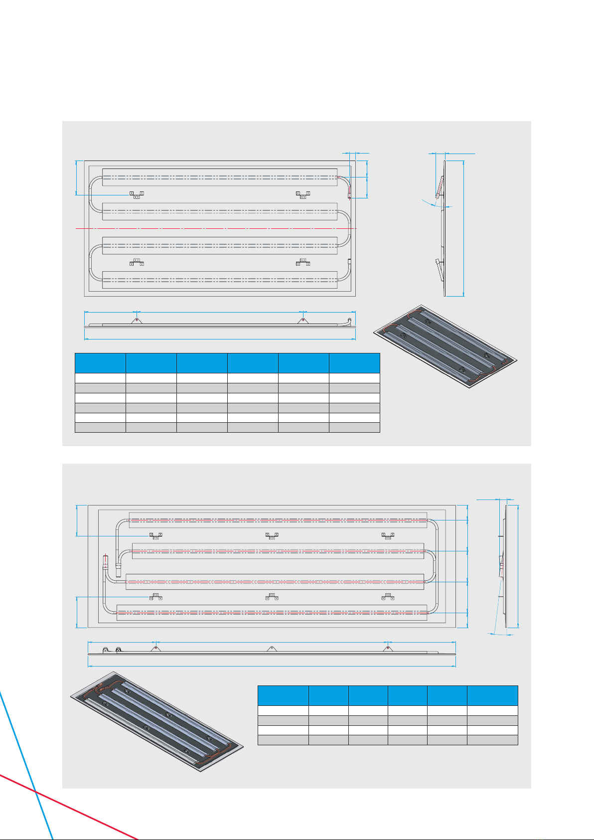
5.4 Bracket Positions
26
72.590.8
150
C
L
595 (600 NOMINAL)
15°
41.6 TYP
"LENGTH"
DIM "A" "B" PITCHES OF "C" DIM "A"
PICTORIAL
ISO VIEW
150
72.572.5 150 150 150
150
595 (600 NOMINAL)
7°
36.6 TYP
"LENGTH"
DIM "A" "B" PITCHES OF "C" DIM "A"
PICTORIAL
ISO VIEW
Nominal
Length Length DIM A DIM B DIM C Hanging
Points
600 590 130 1 330 4
1200 1190 230 1 730 4
1800 1790 330 2 565 6
2400 2390 430 2 765 6
3000 2990 430 2 1065 6
3600 3590 430 3 910 8
Nominal
Length Length DIM A DIM B DIM C Hanging
Points
1800 1790 330 2 565 6
2400 2390 430 2 765 6
3000 2990 430 2 1065 6
3600 3590 430 3 910 8
TWELVE - Standalone Cartridge Panel
TEN - Stand Alone Cartridge Panel
NOTE: 600 X 1800 NOMINAL PANEL SHOWN INSULATION NOT SHOWN IN VIEWS
NOTE: 600 X 1200
NOMINAL PANEL SHOWN
PANELS SYMMETRICAL
AT C
LINSULATION NOT
SHOWN IN VIEWS
17IOM 53, Issue 13 - Thermatile TEN-TWELVE
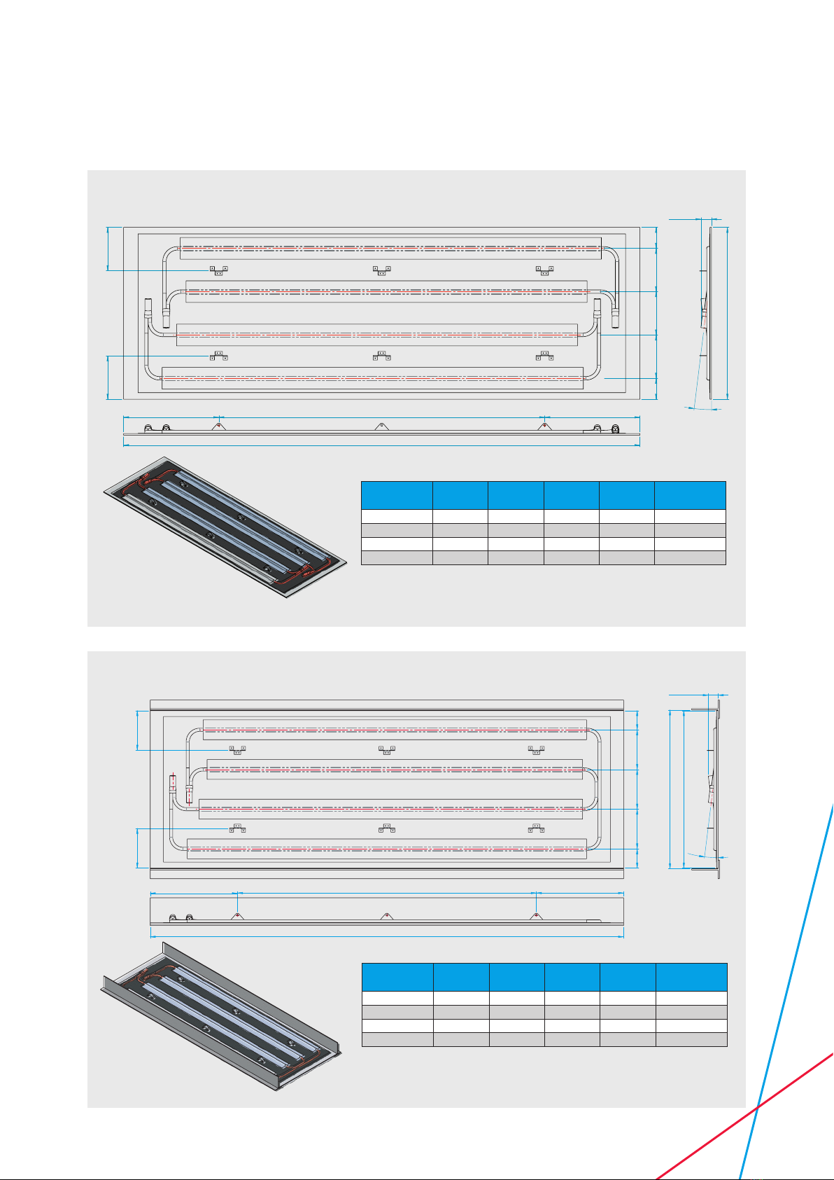
150
72.572.5 150 150 150
150
595 (600 NOMINAL)
7°
36.6 TYP
"LENGTH"
DIM "A" "B" PITCHES OF "C" DIM "A"
PICTORIAL
ISO VIEW
150150
72.5 150 150 150 72.5
NOMINAL WIDTH = 600
PANEL WIDTH = 595
7°
36.6 TYP
"LENGTH"
DIM "A" "B" PITCHES OF "C" DIM "A"
PICTORIAL
ISO VIEW
Nominal
Length Length DIM A DIM B DIM C Hanging
Points
1800 1790 330 2 565 6
2400 2390 430 2 765 6
3000 2990 430 2 1065 6
3600 3590 430 3 910 8
Nominal
Length Length DIM A DIM B DIM C Hanging
Points
1800 1790 330 2 565 6
2400 2390 430 2 765 6
3000 2990 430 2 1065 6
3600 3590 430 3 910 8
TWELVE - Standalone Cartridge Panel = T-Bar
TWELVE - Middle Section Cartridge Panel
NOTE: 600 X 1800 NOMINAL PANEL SHOWN INSULATION NOT SHOWN IN VIEWS
NOTE: 600 X 1800 NOMINAL PANEL SHOWN INSULATION NOT SHOWN IN VIEWS

18 IOM 53, Issue 13 - Thermatile TEN-TWELVE
150150
72.5 150 150 150 72.5
NOMINAL WIDTH = 600
PANEL WIDTH = 595
7°
36.6 TYP
"LENGTH"
DIM "A" "B" PITCHES OF "C" DIM "A"
PICTORIAL
ISO VIEW
155155
77.5 150 150 150 77.5
7°
595 - PANEL WIDTH
605 - CEILING APERTURE
657 - FRAME TO FRAME WIDTH
HOLE
CENTRES
DIM "A" "B" PITCHES OF "C" DIM "A"
PICTORIAL
ISO VIEW
26
11
1
50
2mm
GAP
PANEL FRAME DIMENSIONS
ON DETAIL A
PLASTERBOARD
55
55
"D" PITCHES OF "E"
55
54789
C
L
C
L
HOLES DIMENSIONS ONLY
SYMMETRICAL UPON CENTRELINES
Nominal
Length Length DIM A DIM B DIM C DIM D DIM E Hanging
Points
1800 1790 330 2 565 3 580.67 6
2400 2390 430 2 765 4 585.5 6
3000 2990 430 2 1065 5 588.4 6
3600 3590 430 3 910 6 590.33 8
Nominal
Length Length DIM A DIM B DIM C Hanging
Points
1800 1790 330 2 565 6
2400 2390 430 2 765 6
3000 2990 430 2 1065 6
3600 3590 430 3 910 8
TWELVE - Standalone Cartridge Panel = Plasterboard
TWELVE - Middle Section Cartridge Panel = T-Bar
NOTE: 600 X 1800 NOMINAL PANEL SHOWN
INSULATION NOT SHOWN IN VIEWS
FOR CLARITY HANGING WIRES, HOSES &
INSULATION ARE NOT SHOWN.
CEILING APERTURE DESIGNED TO GIVE
2MM CLEARANCE AROUND PANEL FRAME
NOTE: 600 X 1800 NOMINAL PANEL SHOWN INSULATION NOT SHOWN IN VIEWS

19IOM 53, Issue 13 - Thermatile TEN-TWELVE
155155
"PANEL LENGTH""PANEL LENGTH"
7°
595 - PANEL WIDTH
605 - CEILING APERTURE
657 - FRAME TO FRAME WIDTH
HOLE
CENTRES
DIM "A" "B" PITCHES OF "C" DIM "A""B" PITCHES OF "C"
PICTORIAL
ISO VIEW
26
11
50
2mm
GAP
1
PANEL FRAME DIMENSIONS
ON DETAIL A
PLASTERBOARD
55
55
"D" PITCHES OF "E"
54789
55
55
"D" PITCHES OF "E"
54789
*
C
L
HOLES DIMENSIONS ONLY SYMMETRICAL UPON CENTRELINES
155
155
77.5
150 150 150
77.5
605 - CEILING APERTURE
657 - FRAME TO FRAME WIDTH
15°
595 - PANEL WIDTH
HOLE
CENTRES
DIM "A" DIM "A"
"B" PITCHES OF "C"
PICTORIAL
ISO VIEW
50
2mm
GAP
26
1
11
PANEL FRAME DIMENSIONS
ON DETAIL A
PLASTERBOARD
5554755
55
"D" PITCHES OF "E"
55
HOLES DIMENSIONS ONLY
SYMMETRICAL UPON CENTRELINES
C
L
C
L
Nominal
Length Length DIM A DIM B DIM C DIM D DIM E Hanging
Points
1800 1790 361 2 565 3 571 6
2400 2390 461 2 765 4 578.25 6
3000 2990 461 2 1065 5 582.6 6
3600 3590 461 3 910 6 585.56 8
Nominal
Length Length DIM A DIM B DIM C DIM D DIM E Hanging
Points
1800 1790 330 2 565 3 580.67 6
2400 2390 430 2 765 4 585.5 6
3000 2990 430 2 1065 5 588.4 6
3600 3590 430 3 910 6 590.33 8
TEN - Standalone Cartridge Panel = Plasterboard
TWELVE - Cartridge Panel In Runs = Plasterboard
NOTE: 600 X 1800 NOMINAL PANEL SHOWN
INSULATION NOT SHOWN IN VIEWS
FOR CLARITY HANGING WIRES, HOSES &
INSULATION ARE NOT SHOWN.
CEILING APERTURE DESIGNED TO GIVE
2MM CLEARANCE AROUND PANEL FRAME
NOTE: 600 X 1800 NOMINAL PANEL SHOWN
INSULATION NOT SHOWN IN VIEWS
NOTE: FRAME PANEL SHOWN ON ‘BOTTOM VIEW’ MUSTBE PUSHED UP AGAINST
THE FIRST PANEL SO THAT THE RAMES ARE FLUSH * ANY REMANING GAPS
TOBE FILLED WITH SUITABLE ANTI-PICK MASTIC.
FOR CLARITY HANGING WIRES, HOSES & INSULATION ARE NOT SHOWN.
CEILING APERTURE DESIGNED TO GIVE 2MM CLEARANCE AROUND PANEL FRAME

SPC House
Evington Valley Road
Leicester
LE5 5LU
T: 0116 249 0044
E: spc@spc-hvac.co.uk
spc-hvac.co.uk
IOM 53, Issue 13 - Thermatile TEN-TWELVE
Table of contents
Popular Electric Heater manuals by other brands


Baxi Fires Division
Baxi Fires Division MIRAGE 804 Installer and owner guide

Oceanic
Oceanic OCEAISHT1000W user manual

Helo
Helo SKSM STJ Series product manual

Heatrex
Heatrex Quartzone owner's manual

Trotec
Trotec TEH 70 operating manual

Fired Up Corporation
Fired Up Corporation Sola SPH-15AA instruction manual


