SPE DFG400 Series User manual

DFG400-5 & 5DP
COMPACT FLOOR GRINDER
Operating Manual
This manual is provided to persons purchasing an
SPE machine and may not be reproduced in part or full
without written permission of
SPE International Ltd.
This manual provides the basic information required
and is only to be used as a guideline.
The SPE machines are manufactured and covered by
SPE design registrations granted and pending.
SPE International Ltd reserves the right to alter the
equipment design and specification as required
without notice.
The SPE product range is subject to amendment and
improvement as a result of on going research
Honeyholes Lane, Dunholme, Lincoln LN2 3SU, England
Tel: +44 (0) 1673 860709 Fax: +44 (0) 1673 861119
Email: sales@spe-int.com


DFG400-5 & 5DP
COMPACT FLOOR GRINDER
Operating Manual
DFG400
COMPACT FLOOR GRINDER
This manual covers to the best of our knowledge the operation and maintenance to the
DFG400 floor grinder. Before operation of the equipment the manual should be read and
understood by the operator. The safety regulations must be followed at all times. Service
of electrical components should be carried out by authorised personnel. Failure to follow
these instructions could result in damage to the machine and/or serious personal injury or
death.
Warning
Failure to follow these instructions may result in serious personal injury or death. SPE
disclaims all responsibility for damage to persons or objects arising as a consequence of
incorrect handling of the machine and failure to inspect the machine for damage or other
faults that may influence the operation prior to starting work.
DFG400-5 & DFG400-5DP
The difference between the two variations of machine is as follows:
DFG400-5 This is supplied as standard, fitted with 2no drive plates (part no 6435L (L/H)
and 6435R (R/H)) for use with carborundum grinding blocks, etc with the wedge retaining
system.
DFG400-5DP This is supplied as standard fitted with 2noadaptorplates (partno 5064A)which
will allow the use of diamond grinding plates, etc

DFG400-5 & 5DP
COMPACT FLOOR GRINDER
Operating Manual
INDEX
Page No
1 Starting Work
2 Electrical Instructions
3 Changing the Grinding Blocks and Heads
4 Maintenance
5 Maintenance Checklist
6 Safety
7-8 Accessories
9 Spare Parts Breakdown
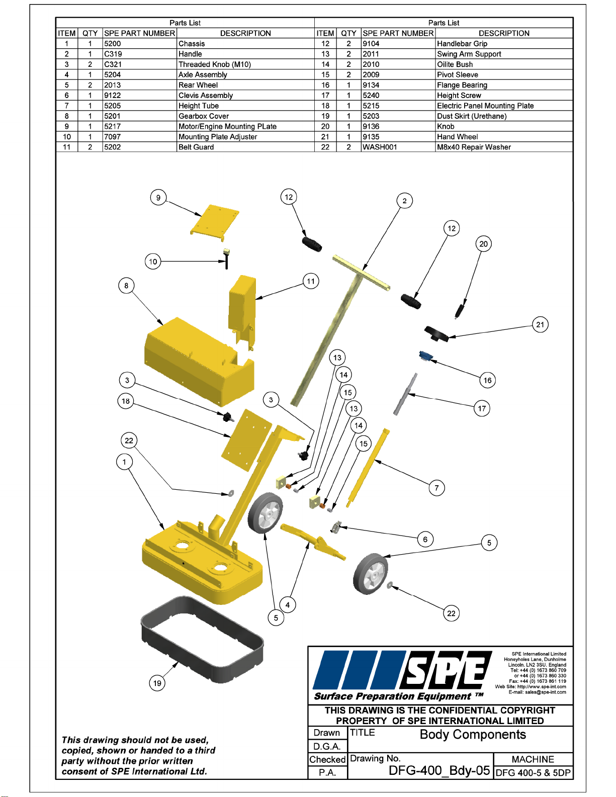
10 Body Components
11 Drive Components (DFG400-5)
12 Drive Components (DFG400-5DP)
13 Wiring Diagram
14 Electrical Components
15 Specifications
Electrical Requirements
16 Noise/Vibration Assessment
17 Warranty
18 Declaration of Conformity
19 Conditions of Sale

DFG400-5 & 5DP
COMPACT FLOOR GRINDER
Operating Manual
STARTING WORK
Check the following prior to starting the equipment.
Check all nuts and bolts for tightness
Check the drive belt condition and tension
Check the plugs and cables for damage
1. Before starting work, check that the set up of the machine and the grinding heads has
been completed as described below to ensure even wear to the heads.
2. It is vital at this stage that the machine should be set to grind the floor along the same
plane. Incorrect set up will result in uneven head wear, vibration and damage to the flexible
couplings that support the heads.
3. Raise the dust skirt by approximately 20mm and check that the grinding heads are in full
contact with the floor surface.
4. With the machine set on the floor surface to be ground, check the level of the floor with a
spirit level. Then place the spirit level on the side of the machine above the dust skirt.
Adjust the rear wheel height using the hand wheel (part no 9135), until the level of the
machine is the same as the floor level.
5. Push the dust extraction skirt down to the floor surface.
6. Connect the vacuum hose to the dust extraction port, if a dust control vacuum is being
used. We recommend the SPE VAC316 3 motor vacuum for dust control.
7. Ensure that the power supply is correct for the machine (see page 2 for further details).
Connect the machine to the power supply.
8. To start the machine
Lift the grinding heads slightly by tipping the machine onto its rear wheels.
Turn the switch (Part no 9254) on the electric panel, to the start position and hold for 2 - 3
seconds, then release the switch to the run ‘1’ position.
Lower the machine onto the floor, moving the heads evenly across the surface to ensure a
smooth ground finish.
9. To stop the machine, turn the switch on the panel to the off position.
Never allow the machine to stop moving whilst grinding heads are in contact with the
surface.
1

DFG400-5 & 5DP
COMPACT FLOOR GRINDER
Operating Manual
ELECTRICAL INSTRUCTIONS
The points raised are based on many years practical experience not on text book theory. If
you follow these guidelines your time on site will be productive rather than frustrating.
The DFG400 110v machine is supplied with a specifically commissioned electric motor and
starter switch assembly. Each unit is fully tested and the safety overload relays have been
calibrated and set according to the manufacturers specifications. In the event of the
malfunction on a new machine the owner should first check that the power supply on site is
suitable and adequate.
The motor ideally requires a 32 amp, 110v power supply.
To avoid voltage drop the cable must be a minimum of 4.0mm. The maximum length of
cable must not exceed 30 metres.
The transformer must have a continuous rated output of at least 3kva. In practice this can
mean that a 5kva transformer must be used. Manufacturers of transformers have different
methods of rating their equipment.
The transformer and all cables should be fitted with 32 amp 110v plugs and sockets.
All cables should be fully uncoiled and never left wrapped around cable reels or tied in
loops.
The 240v supply to the 110v transformer should be rated to at least 20 amp if supply
problems are to be avoided.
If the power is to be generated, the DFG400 110v requires a minimum 10kva generator.
The motor is protected with a safety trip in the panel which will cut out the motor if it is
overloaded. Should the trip be activated then you must wait for the motor to cool down
isolate the power supply, open the panel and reset the trip.
If the motor repeatedly cuts out then it will be damaged. The possible causes are either an
inadequate power supply, overloading of the machine, or an electrical fault.
2

DFG400-5 & 5DP
COMPACT FLOOR GRINDER
Operating Manual
CHANGING THE GRINDING BLOCKS
1. Disconnect from the power supply.
2. Tilt the machine backwards onto its handle. The machine must be secured and
supported.
3. Drive out the wooden wedge securing the grinding block and remove the remains of the
grinding block from the plate. Repeat this process for all the blocks.
4. Place a new block into the holder on the plate and hold whilst inserting a new wooden
wedge into the inside edge of the block. Drive in the wooden wedge to secure the block
firmly. Repeat this process for all the blocks.
5. Lower the machine back to the upright position.
6. Check machine level (see page 1) and carry out adjustments if necessary.
7. Reconnect to the power supply.
CHANGING THE GRINDING HEADS
1. Disconnect from the power supply.
2. Tilt the machine backwards on to its handle. The machine must be secured and
supported.
3. Make sure the grinding heads are cool to the touch.
4. Use an allen key to undo the countersunk screws securing the Grinding Heads to the
adaptor plates.
5. Remove the grinding head and replace.
6. Ensure the grinding heads are seated to the adaptor plates correctly prior to tightening
the countersunk screws diagonally.
7. Lower the machine back to the upright position.
8. Check machine level (see page 1) and carry out adjustments if necessary.
9.Reconnect to the power supply.
CHECK FOR CORRECT WEAR RATE AFTER QUARTER OF AN HOUR AND AGAIN AT
HALF AN HOUR INTERVALS - THIS WILL GIVE AN IDEA OF WEAR RATE
3

DFG400-5 & 5DP
COMPACT FLOOR GRINDER
Operating Manual
MAINTENANCE
Prior to any maintenance or adjustment disconnect the machine from the power supply.
AFTER USE:
-Clean the machine to remove all build up of dust and surface residue. If using a hose
pipe or pressure water take care that water is not directed onto electrical components
and switches. (Note: Motors and switches are not waterproof)
-Ensure the height adjustment thread is cleaned and then lightly oiled. Periodically it
should be removed and the female, threaded section cleaned out and oiled regularly to
maintain a light, smooth height adjustment.
-The drive belts will give a long and trouble free operating life if basic procedures are
followed. The drive belts are tensioned by adjusting the motor mounting plate. It is
important that the drive belts are not over tensioned. Serious damage could be caused
to the gearboxes and/or drive motor if the belts are excessively tight.
-All components should be checked daily for tightness and the drive belts for tension.
-The flexible drive couplings that support the grinding heads should be checked on a
weekly basis.
-Any excess vibration due to uneven head wear should result in the heads being
changed to eliminate damage to couplings.
4

DFG400-5 & 5DP
COMPACT FLOOR GRINDER
Operating Manual
BASIC MAINTENANCE CHECKLIST
DAILY:
Check all nuts and bolts for tightness.
Check the condition of the grinding heads
Check the belt tension and condition
Check the plugs and cables
WEEKLY:
All of the above with the following.
Grease all moving parts on the height adjustment mechanism
Check the flexible drive couplings
Check the support wheels and grease
MONTHLY:
All of the above with the following,
Strip down fully the winding mechanism
Clean all threads and re grease
Check gearbox flexi-coupling
Check gearbox oil seals
5

DFG400-5 & 5DP
COMPACT FLOOR GRINDER
Operating Manual
SAFETY
Only trained operatives should be allowed to work the DFG400 floor grinder.
All operatives should wear ear defenders, goggles and an effective dust mask. Note: It is
possible that the noise level produced by the DFG400 could exceed 90dbA. Personal
noise protection must be worn and the equipment must be used in line with guidelines laid
down by the Health & Safety Executive.
Never leave the DFG400 unattended whilst in use. Always stop the motor prior to leaving
the machine.
Always ensure that all power leads are disconnected before attempting to service the
machine. The service of electrical components should be carried out by authorised
personnel. Never tip the machine completely backwards until the grinding plates have
stopped rotating, just raise slightly.
Vibration will occur at various levels dependent on the attachments and work being
completed. However SPE have assessments conducted under test conditions detailed in
the operating manual (see page 16). It is recommended that additional tests are taken on
site to provide the operator with accurate information on using the equipment within the
guidelines laid down by the Health & Safety Executive.
Never operate the machine without a dust extraction skirt or with the dust extraction skirt
raised.
NOTE:
1. NEVER OPERATE THE COMPACT FLOOR GRINDER WITHOUT BELT GUARDS
FITTED
2. NEVER OPERATE THE COMPACT FLOOR GRINDER IN WET CONDITIONS AS
ELECTRICAL COMPONENTS ARE NOT WATERPROOF
6

DFG400-5 & 5DP
COMPACT FLOOR GRINDER
Operating Manual
ACCESSORIES
Part No
Description
Application
6401
Economy grade 250mm
10 segment (blue)
Economical removal of most types of
adhesives and surface contaminants.
Excellent for using on rougher surfaces
as a first grind. Can be used wet or dry.
6402
Super Agressive 250mm
10 segment (red)
Designed for the removal of S/L and
epoxy coatings in a commercially viable
way. Can be used for the majority of
aggressive grinding applications and will
give extended wear on heads.
Can be used wet or dry.
6403
Standard Grade 250mm
16 segment (blue)
Removal and grinding of most types of
concrete floor in preparing for follow on
coatings. General all purpose head for
most grinding works.
Can be used wet or day.
6404
High performance 250mm
20 segment (blue)
Fast removal and grinding of most types
of plain and painted concrete floors. Will
key floors for coatings, removal of high
spots, lip edges etc. Suitable for first and
second stage grinding to terrazzo and
aggregated seamless floors.
Can be used wet or dry.
6405
Button head 250mm
16 segment (blue)
For the removal of the thicker adhesive
on sand / cement screed whether open or
closed. Will cope with large volume areas
in a cost effective manner. To be used
with softer elastomeric and thin film
coatings.
6403C
Fine grit 250mm 16 segment
(purple)
Finishing and polishing of cementitious
polyurethane, epoxy based
terrazzo,terrazzo tiles and decorative
aggregated concrete flooring.
7

DFG400-5 & 5DP
COMPACT FLOOR GRINDER
Operating Manual
6435L
Carborundum grinding block holder
drive plate (L/H)
Drive plate for the carborundum grinding
blocks
6435R
Carborundum grinding block holder
drive plate (R/H)
Drive plate for the carborundum grinding
blocks
6416
6417
6418
Carborundum grinding blocks
Fine
Medium
Coarse
For economical polishing and grinding
removal of high spots, over watered
slabs, rain damaged slabs, lip edges etc.
6436
Standard grade Diamond block.
Diamond grinding block to be used on
DFG400. Removal of old coatings and
grinding most types of concrete floor.
Secured using wedge
P53534
Wooden wedge
To secure grinding blocks into DFG400
floor grinder
5064A
Adaptor plate
Drive adaptor plate for use of diamond
plates, etc.
8

DFG400-5 & 5DP
COMPACT FLOOR GRINDER
Operating Manual
9


DFG400-5 & 5DP
COMPACT FLOOR GRINDER
Operating Manual
ELECTRICAL COMPONENTS
QTY
DESCRIPTION
SPE PART NO.
1
Panel box
SP2518-11
1
Hinge kit
SP190005
1
Back plate
9249
1
Rotary switch
9254
1
Contactor
9255
1
Contact breaker
9256
1
Plug retaining plate
9250
1
Start capacitor
156MF@240V
1
Run capacitor
70MF@450V
2
Conduit gland
9258
1
Conduit (MTR)
9259
14

DFG400-5 & 5DP
COMPACT FLOOR GRINDER
Operating Manual
SPECIFICATION SHEET
Specifications
Type
Electric 1 Phase
Part Number
DFG400-5
DFG400-5DP
Power Output
2.2kw
Voltage
110v
Cycles
50hz
Head Speed r.p.m.
245
Engine motor speed r.p.m.
2800
Machine Dimensions (mm)
Length
Width
Height
Weight (kg)
820
560
700
86
Ballast Weight (kg)
-
Electrical Requirements
Volts
Plug Size
Cable Size (mm)
Norm Cable Length
Transformer
Generator
110v
32 Amp 3 Pin
4.0 - 3 Core
30 metres
5 kva
10 kva
15

DFG400-5 & 5DP
COMPACT FLOOR GRINDER
Operating Manual
RECORD OF NOISE AND VIBRATION ASSESSMENT
Manufacturer:
SPE
Type:
Compact Floor Grinder
Model No.
DFG400-5 Electric
Operation :
Concrete floor surface
Inserted Tool:
Carborundum blocks
HAV Note:
Operc
HAND-ARM VIBRATION
Frequency Weighted Energy Equivalent Accelerations (ah,w)
Measurement
Position
Acceleration (m/s2)
Vector Sum
Handle
1.2
NOISE LEVELS
Sound Power Level (LWA)
LWA at Octave Band Centre Frequency (Hz)
Sound
Power
Level
LWA
63
125
250
500
1000
2000
4000
8000
50.8
72.3
78.8
88.2
85.5
98.5
94.3
83.5
100.4
Operator's Ear
LAeq,T at Octave Band Centre Frequency (Hz)
Overall
Level
(LAeq,T)
LPeak
dB(C)
63
125
250
500
1000
2000
4000
8000
34.4
58.4
62.7
76.2
73.6
82.5
75.8
63.9
83.8
101.3
16
This manual suits for next models
2
Table of contents
Other SPE Floor Machine manuals


Popular Floor Machine manuals by other brands


Truvox
Truvox HYDROMIST 13 user manual

SAINT-GOBAIN ABRASIVES
SAINT-GOBAIN ABRASIVES Norton Clipper CG 250 E Operating intructions

Nilfisk-Advance
Nilfisk-Advance SC400 43E Instructions for use

Truvox International
Truvox International Multiwash Pro Series user manual

Husqvarna
Husqvarna BMG 780 Operator's manual

HAKO
HAKO Hakomatic E 10 instruction manual


