SPE DFG460-5 User manual

DFG460-5
Diamond Floor Grinder
Operating Manual
This manual is provided to persons purchasing an
SPE machine and may not be reproduced in part or full
without written permission of
SPE International Ltd.
This manual provides the basic information required
and is only to be used as a guideline.
The SPE machines are manufactured and covered by
SPE design registrations granted and pending.
SPE International Ltd reserves the right to alter the
equipment design and specification as required
without notice.
The SPE product range is subject to amendment and
improvement as a result of on going research
Honeyholes Lane, Dunholme, Lincoln LN2 3SU, England
Tel: +44 (0) 1673 860709 Fax: +44 (0) 1673 861119
Email: sales@spe-int.com

DFG460-5
Operating Manual
DFG460 Triple Head
Floor Grinder
OPERATING MANUAL
This manual covers to the best of our knowledge the operation and maintenance of the
DFG460-5 diamond floor grinder. Before operation of the equipment the manual should be
read and understood by the operator. The safety regulations must be followed at all times.
Service of electrical components should be carried out by authorised personnel.
WARNING
Failure to follow these instructions may result in serious personal injury ordeath. SPEdisclaims
all responsibility for damage to persons or objects arising as a consequence of incorrect
handling of the machine and failure to inspect the machine for damage or other faults that may
influence the operation prior to starting work.

DFG460-5
Operating Manual
INDEX
Page No
1 Starting Work
2 DFG460 Tooling
3 Maintenance
4 Safety
5 Spare Parts Breakdowns
6-7 Main Gearbox Assembly
8-9 Main Drive Assembly
10-11 Pivot Frame Assembly
12-13 Axle Frame Assembly
14-15 Adjustable Strut Assembly
16-17 Handle Assembly
18-19 Drive Gear Assembly
20-21 Intermediate Gear Assembly
22-23 Driven Gear Assembly
24 Electrical Components
25 Specification Sheet
26 Warranty
27 Declaration of Conformity
28 Conditions of Sale

DFG460-5
Operating Manual
STARTING WORK
1. BEFORE STARTING WORK ENSURE THAT THE GRINDING HEADS HAVE BEEN
FITTED, SEE PAGE 3
2. Ensure the power supply is correct for DFG460-5 - This should be a 110V 32 amp supply
from the mains or generated with a minimum of 8 kVA on 50 cycles. See Page 2 for further
details.
3. Connect a vacuum to the port at the rear of the machine to control the dust.
4. The height of the operating handle can be adjusted by using the hand-wheel at the rear of
the machine. Turning the hand-wheel anti-clockwise will raise the handle and clockwise will
lower the handle.
The grinding head of the machine can pivot and the movement can be altered by adjusting
the two grinding head stops at the front and rear of the frame.
5. Turn on the vacuum.
6. Start the machine by turning the switch on the panel to the start position. Hold for 2-3
seconds for the motor to start and then release. The switch will return to its run position.
7. To stop the machine, turn the switch to the off position.
The machine can be disassembled to enable it to fit into a small vehicle. Unplug the motor
lead from the electrical panel then take out the pins in the yokes at the base of the main
handle and also the one at the bottom of the height adjustment tube, lift the handle assembly
from the frame of the machine.
1

DFG460-5
Operating Manual
DFG460 TOOLING
The DFG460 is fitted with three drive plates that use a quick release tooling system. These
are fitted to the machine with three countersunk screws per plate. Ensure that these plates
are securely fastened to the machine prior to fitting any tools.
METAL GRINDING TOOLS
1. Disconnect the machine from the power supply.
2. Tip the DFG460 backwards onto the operator handle. The machine must be secured and
supported.
3. Fit the metal tools into the drive plates by locating the dovetail on the back of the tool into
the chamfered slot in the drive plate and slide outwards. Give the tool a tap outwards to lock
into position.
4. Repeat the above process to fit the other eight tools into the drive plates.
5. Removal of existing tools is the reverse of the above. Tap the tool inwards to unlock and
slide out of the slot in the drive plate.
6. After fitting the tools, gently lower the machine back onto the floor surface.
RESIN POLISHING TOOLS
The resin tools are fitted as a two piece system. Fitting will require a set of resin tool holders
(part no 5495 (x9)) with the Velcro backing that will accept most standard 60mm diameter
Velcro backed resin tools.
1. Disconnect the machine from the power supply.
2. Tip the DFG460 backwards onto the operator handle, the machine must be secured and
supported.
3. Fit the resin tool holders into the drive plates by locating the dovetail on the back of the
tool holder into the chamfered slot in the drive plate and slide outwards, give the tool a tap
outwards to lock into position.
4. Repeat the above process to fit the other eight tool holders into the drive plates.
5. Once all the tool holders are in place, press on the required resin tools onto the velcro
backing.
6. Changing resin tools only involves removing from the tool holder and replacing.
To remove the tool holders, tap inwards to unlock and slide out of the slot in the drive plate.
7. After fitting of the tools, gently lower the machine back onto the floor surface.
NOTE: Always use the same type and bond of tool on each of the three heads, equally worn
tools must be fitted as a set.
To ensure the correct tool is being used, check wear rates after quarter of an hour and again
at half hourly intervals, this will give an indication of total wear rates and cost per square
metres.
2

DFG460-5
Operating Manual
MAINTENANCE
AFTER USE:
Clean the machine to remove all build up of dust and surface residue. If using a hose pipe or
pressure washer, take care that water is not directed onto electrical components and switches.
(Note: Motors and switches are not waterproof)
Ensure the height adjustment thread is cleaned and then lightly oiled. Periodically it should be
removed and the female threaded section cleaned out and oiled regularly to maintain a light,
smooth height adjustment.
The flexible couplings that support the drive plates should be checked on a weekly basis, the
couplings should be firm without excessive movement.
The planetary gear case is sealed and should not require any maintenance, the internal gears
are lubricated with Lithium EPO grease.
All components should be checked daily for tightness.
All plugs, sockets and electrical leads should be checked for condition and damage.
Periodically check the oil level in the drive gearbox. Ensure that the machine is level and
remove the top blanking plug from the gearbox at the front of the machine. If oil comes out of
the hole when the plug is removed then the gearbox contains sufficient oil, if not then top up the
gear box using a SY320 grade gear oil.
3

DFG460-5
Operating Manual
SAFETY
Only trained operatives should be allowed to work the DFG460 range of floor grinders.
Note: It is possible that the noise level produced by the Diamond Floor Grinder could exceed
90dbA. Appropriate PPE must be worn and the equipment must be used in line with
guidelines laid down by the Health & Safety Executive.
Always ensure that all power leads and hoses are disconnected before attempting to service
the machine. Never tip the machine backwards until the grinding plates have stopped
rotating and the machine has been isolated at the main supply.
Noise and vibration will occur at various levels dependent on the grindingattachmentsand work
being completed. It is recommended that tests are taken on site to provide the operator with
accurate information on using the equipment within the guidelines laid down by the Health &
Safety Executive.
NOTE:
1. NEVER OPERATE THE DFG460 FLOOR GRINDER OUTDOORS IN WET CONDITIONS AS
THE ELECTRICAL COMPONENTS ARE NOT WATERPROOF
2. NEVER OPERATE THE DFG460 WITH THE HEADS RAISED FROM THE FLOOR
3. THE SERVICE OF ELECTRICAL COMPONENTS SHOULD BE CARRIED OUT BY
AUTHORISED PERSONNEL ONLY.
4

DFG460-5
Operating Manual
5

[
6HH1RWH
6HH1RWH
%RWK6LGHV
6HH1RWH
%RWK6LGHV
[
[
[
3ODQ(OHYDWLRQ2I*HDUER[
:LWK7RS3ODWH5HPRYHG
2Q$VVHPEO\*HDUV7R0HVK
6PRRWKO\$QG5XQ7RJHWKHU
:LWKRXW%LQGLQJ
,PSRUWDQW)LOO:LWKJ
2I(322/LWKLXP
*UHDVH2Q$VVHPEO\
5HPRYH6KDUS(GJHV&RUQHUV
$OO0DFKLQHG6XUIDFHV7R%H6TXDUH3DUDOOHO
1RWH6HDO*HDUER[2Q$VVHPEO\:LWK*DVWLWH0XOWL3XUSRVH6LOLFRQH6HDODQW&OHDU
5(9,6,216
5(9
'(6&5,37,21
'$7(
$33529('
,1,7,$/5(/($6(
%-
'21276&$/(
/LVWRI3DUWVDQG0DWHULDOV
$
'5$:,1*1R
7,7/(
')*0DLQ*HDUER[$VVHPEO\
')*
'$7(
*(1(5$/72/(5$1&(
0081/(66
27+(5:,6(67$7('
$//',0(16,216
,10081/(66
27+(5:,6(67$7('
7+,5'$1*/(
),1,6+
0$7(5,$/
47<
6&$/(
'5$:1%<
'5$:,1*1R
7,7/(
')*0DLQ*HDUER[$VVHPEO\
')*
7+,6'2&80(17,635,9$7($1'
&21),'(17,$/$1'7+(3523(57<
2)63(,17(51$7,21$//WG,70867
127%(&23,('2568%0,77('72
$1<7+,5'3$57<:,7+2877+(
&216(172)63(,17(51$7,21$//WG
685)$&(35(3$5$7,21(48,30(17
63(,QWHUQDWLRQDO/WG
+RQH\KROHV/DQH
'XQKROPH
/LQFROQVKLUH
/168
(QJODQG
7HO
)D[
:HE6LWHKWWSZZZVSHLQWFRP
(PDLOLQIR#VSHLQWFRP
*'&

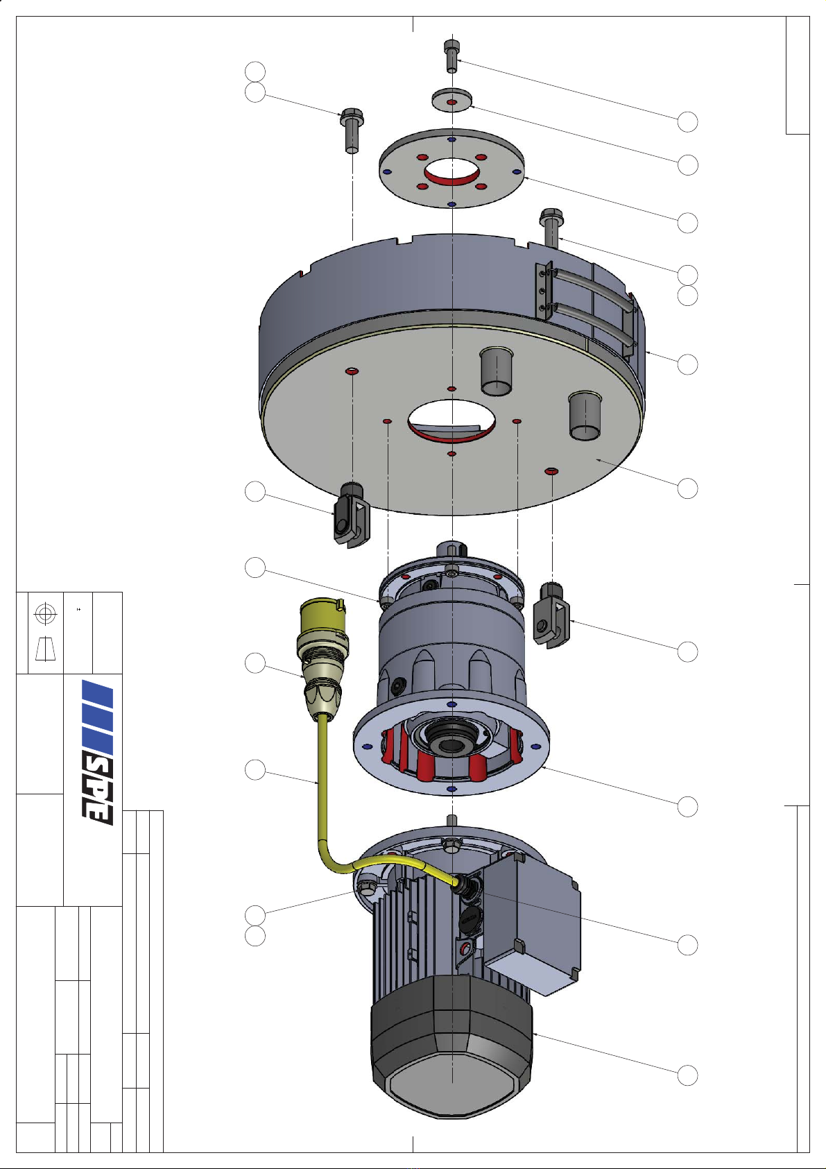
DFG460-5
Operating Manual
MAIN GEARBOX ASSEMBLY
ITEM
QTY
PART NUMBER
DESCRIPTION
1
1
5504
Upper Gear Plate
2
-
See drawing no. DFG-460-0066-1
Page 18-19
3
-
See drawing no. DFG-460-0067-1
Page 20-21
4
-
See drawing no. DFG-460-0068-1
Page 22-23
5
1
5525
Main Hub
6
1
5505
Upper Gear Ring
7
1
5506
Lower Gear Ring
8
1
5507
Lower Gear Plate
9
1
7424
Lip Seal
10
6
BOLT246
M8 x 16 Cap HD Skt Screw
11
6
WASHER004
M8 Flat Washer
12
6
WASHER024
M8 Spring Washer
13
6
BOLT226
M6 x 45 Cap HD Skt Screw
14
12
BOLT225
M6 x 40 Cap HD Skt Screw
15
6
BOLT224
M6 x 12 Cap HD Skt Screw
16
18
NUT043
M6 Nyloc Nut
17
24
WASHER003
M6 Flat Washer
7
1RWH$OO)DVWHQHUV7R%H6HFXUHG:LWK/RFNWLWH2Q$VVHPEO\
5(9,6,216
5(9
'(6&5,37,21
'$7(
$33529('
92/7$*(83'$7(
%-
'21276&$/(
/LVWRI3DUWVDQG0DWHULDOV
$
'5$:,1*1R
7,7/(
')*0DLQ'LYH$VVHPEO\
96LQJOH6SHHG
')*
'$7(
*(1(5$/72/(5$1&(
0081/(66
27+(5:,6(67$7('
$//',0(16,216
,10081/(66
27+(5:,6(67$7('
7+,5'$1*/(
),1,6+
0$7(5,$/
47<
6&$/(
'5$:1%<
'5$:,1*1R
7,7/(
7+,6'2&80(17,635,9$7($1'
&21),'(17,$/$1'7+(3523(57<
2)63(,17(51$7,21$//WG,70867
127%(&23,('2568%0,77('72
$1<7+,5'3$57<:,7+2877+(
&216(172)63(,17(51$7,21$//WG
685)$&(35(3$5$7,21(48,30(17
63(,QWHUQDWLRQDO/WG
+RQH\KROHV/DQH
'XQKROPH
/LQFROQVKLUH
/168
(QJODQG
7HO
)D[
:HE6LWHKWWSZZZVSHLQWFRP
(PDLOLQIR#VSHLQWFRP
*'&

DFG460-5
Operating Manual
MAIN DRIVE ASSEMBLY
ITEM
QTY
PART NUMBER
DESCRIPTION
1
1
5520
Gearbox Retaining Plate
2
1
5539
Gearbox Lock Washer
3
2
5513
Yoke & Clevis Pin
4
1
5511
Gearbox
5
1
7017
Electric Motor
6
1
5512
Dust Skirt
2
7331
Dust Skirt Spring
7
1
5503
Cowl
8
1
SPCG/LNM20
Cable Gland
9
1
SP230-404
32A 4Pin Trailing Plug
10
1
7513
4.0mm² Arctic Yellow Cable
11
2
BOLT094
M16 x 45 Set Screw
12
2
WASHER008
M16 Flat Washer
13
4
BOLT082
M12 x 40 Set Screw
14
1
BOLT282
M12 x 30 Cap HD Skt Screw
15
4
WASHER006
M12 Flat Washer
16
4
BOLT263
M10 x 30 Cap HD Skt Screw
9
5HPRYH6KDUS(GJHV&RUQHUV
$OO0DFKLQHG6XUIDFHV7R%H6TXDUH3DUDOOHO
1RWH$OO)DVWHQHUV7R%H6HFXUHG:LWK/RFNWLWH2Q$VVHPEO\
5(9,6,216
5(9
'(6&5,37,21
'$7(
$33529('
,1,7,$/5(/($6(
%-
'21276&$/(
/LVWRI3DUWVDQG0DWHULDOV
$
'5$:,1*1R
7,7/(
')*3LYRW)UDPH$VVHPEO\
')*
'$7(
*(1(5$/72/(5$1&(
0081/(66
27+(5:,6(67$7('
$//',0(16,216
,10081/(66
27+(5:,6(67$7('
7+,5'$1*/(
),1,6+
0$7(5,$/
47<
6&$/(
'5$:1%<
'5$:,1*1R
7,7/(
176
')*
7+,6'2&80(17,635,9$7($1'
&21),'(17,$/$1'7+(3523(57<
2)63(,17(51$7,21$//WG,70867
127%(&23,('2568%0,77('72
$1<7+,5'3$57<:,7+2877+(
&216(172)63(,17(51$7,21$//WG
685)$&(35(3$5$7,21(48,30(17
63(,QWHUQDWLRQDO/WG
+RQH\KROHV/DQH
'XQKROPH
/LQFROQVKLUH
/168
(QJODQG
7HO
)D[
:HE6LWHKWWSZZZVSHLQWFRP
(PDLOLQIR#VSHLQWFRP
*'&

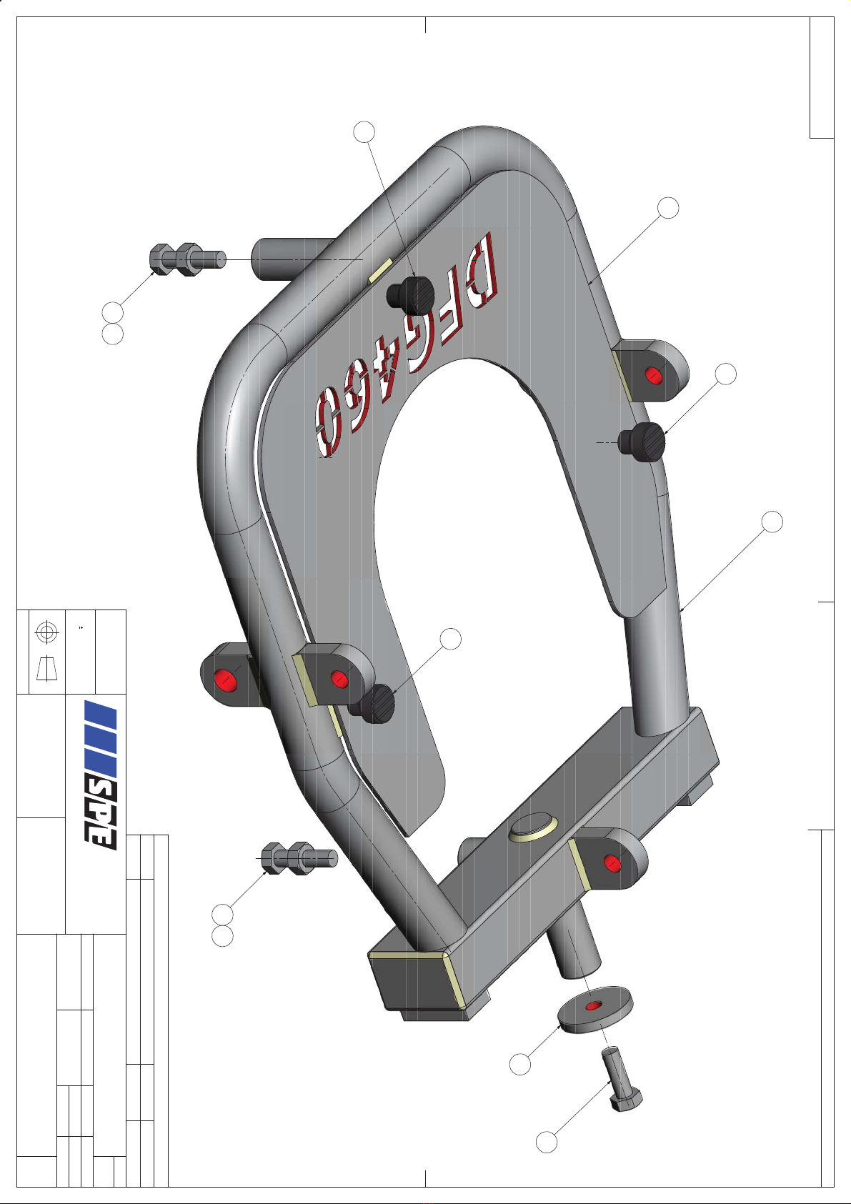
DFG460-5
Operating Manual
PIVOT FRAME ASSEMBLY
ITEM
QTY
PART NUMBER
DESCRIPTION
1
1
5501
Frame
2
1
5540
Frame Lock Washer
3
1
5508
Cover Plate
4
3
5515
Thumb Screw
5
2
BOLT064
M10 x 40 Set Screw
6
1
BOLT062
M10 x 30 Set Screw
7
2
NUT005
M10 Nut
11

2YHUDOO
5HI
5HI
5HI
5HI
1RWH$OO)DVWHQHUV7R%H6HFXUHG:LWK/RFNWLWH2Q$VVHPEO\
5(9,6,216
5(9
'(6&5,37,21
'$7(
$33529('
,1,7,$/5(/($6(
%-
'21276&$/(
/LVWRI3DUWVDQG0DWHULDOV
$
'5$:,1*1R
7,7/(
')*$[OH)UDPH$VVHPEO\
')*
'$7(
*(1(5$/72/(5$1&(
0081/(66
27+(5:,6(67$7('
$//',0(16,216
,10081/(66
27+(5:,6(67$7('
7+,5'$1*/(
),1,6+
0$7(5,$/
47<
6&$/(
'5$:1%<
'5$:,1*1R
7,7/(
176
')*$[OH)UDPH$VVHPEO\
')*
7+,6'2&80(17,635,9$7($1'
&21),'(17,$/$1'7+(3523(57<
2)63(,17(51$7,21$//WG,70867
127%(&23,('2568%0,77('72
$1<7+,5'3$57<:,7+2877+(
&216(172)63(,17(51$7,21$//WG
685)$&(35(3$5$7,21(48,30(17
63(,QWHUQDWLRQDO/WG
+RQH\KROHV/DQH
'XQKROPH
/LQFROQVKLUH
/168
(QJODQG
7HO
)D[
:HE6LWHKWWSZZZVSHLQWFRP
(PDLOLQIR#VSHLQWFRP
*'&

DFG460-5
Operating Manual
AXLE FRAME ASSEMBLY
ITEM
QTY
PART NUMBER
DESCRIPTION
1
1
5541
Axle Assembly
2
14
WASHER009
M20 Flat Washer
3
2
2013
Rear Wheel
4
1
5031
Oilite Bush
5
2
BOLT042
M8 x 20 Set Screw
6
2
WASHER053
M8 x 40 Repair Washer
13
$OWHUQDWLYHO\)LW
6SULQJ3LQ2Q$VVHPEO\
5HPRYH6KDUS(GJHV&RUQHUV
$OO0DFKLQHG6XUIDFHV7R%H6TXDUH3DUDOOHO
5(9,6,216
5(9
'(6&5,37,21
'$7(
$33529('
,1,7,$/5(/($6(
%-
'21276&$/(
/LVWRI3DUWVDQG0DWHULDOV
')*
')*$GMXVWDEOH6WUXW$VVHPEO\
7,7/(
'5$:,1*1R
$
7+,5'$1*/(
*'&
7HO
)D[
:HE6LWHKWWSZZZVSHLQWFRP
(PDLOLQIR#VSHLQWFRP
63(,QWHUQDWLRQDO/WG
+RQH\KROHV/DQH
'XQKROPH
/LQFROQVKLUH
/168
(QJODQG
7+,6'2&80(17,635,9$7($1'
&21),'(17,$/$1'7+(3523(57<
2)63(,17(51$7,21$//WG,70867
127%(&23,('2568%0,77('72
$1<7+,5'3$57<:,7+2877+(
&216(172)63(,17(51$7,21$//WG
')*
7,7/(
'5$:,1*1R
$
'5$:1%<
6&$/(
47<
0$7(5,$/
),1,6+
7+,5'$1*/(
'$7(
685)$&(35(3$5$7,21(48,30(17
$//',0(16,216
,10081/(66
27+(5:,6(67$7('
*(1(5$/72/(5$1&(
0081/(66
27+(5:,6(67$7('
176
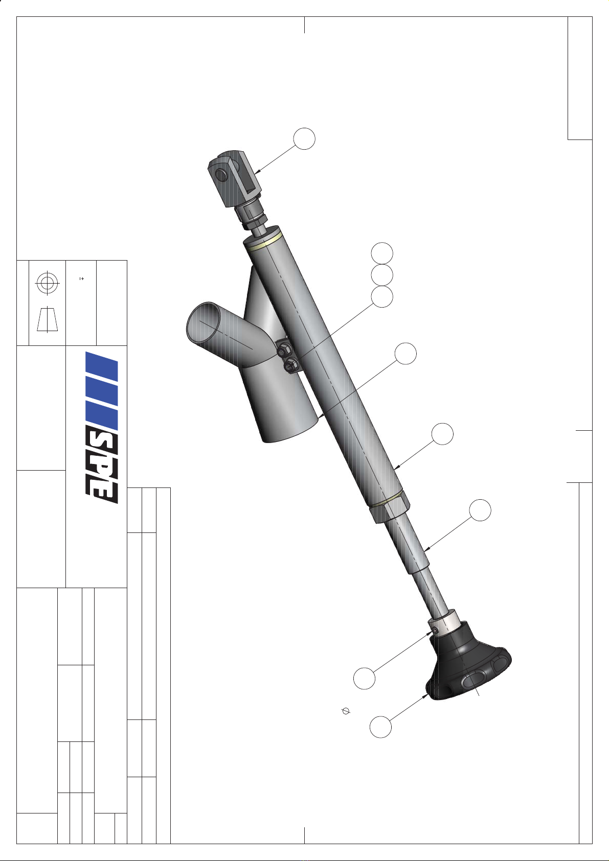
DFG460-5
Operating Manual
ADJUSTABLE STRUT ASSEMBLY
ITEM
QTY
PART NUMBER
DESCRIPTION
1
1
5509
Height Rod
2
1
5510
Hose Y Piece
3
1
5518
Height Screw
4
1
9122
Yoke & Clevis Pin
5
1
5519
Handwheel
6
2
BOLT227
M6 x 16 Cap HD Skt Screw
7
2
NUT043
M6 Nyloc Nut
8
2
WASHER003
M6 Flat Washer
9
1
BOLT302
M6 Grub Screw
15
5HI
5HI
1RWH$OO)DVWHQHUV7R%H6HFXUHG:LWK/RFNWLWH2Q$VVHPEO\
5(9,6,216
5(9
'(6&5,37,21
'$7(
$33529('
,1,7,$/5(/($6(
%-
'21276&$/(
/LVWRI3DUWVDQG0DWHULDOV
$
'5$:,1*1R
7,7/(
')*+DQGOH$VVHPEO\
')*
'$7(
*(1(5$/72/(5$1&(
0081/(66
27+(5:,6(67$7('
$//',0(16,216
,10081/(66
27+(5:,6(67$7('
7+,5'$1*/(
),1,6+
0$7(5,$/
47<
6&$/(
'5$:1%<
'5$:,1*1R
7,7/(
')*+DQGOH$VVHPEO\
')*
7+,6'2&80(17,635,9$7($1'
&21),'(17,$/$1'7+(3523(57<
2)63(,17(51$7,21$//WG,70867
127%(&23,('2568%0,77('72
$1<7+,5'3$57<:,7+2877+(
&216(172)63(,17(51$7,21$//WG
685)$&(35(3$5$7,21(48,30(17
63(,QWHUQDWLRQDO/WG
+RQH\KROHV/DQH
'XQKROPH
/LQFROQVKLUH
/168
(QJODQG
7HO
)D[
:HE6LWHKWWSZZZVSHLQWFRP
(PDLOLQIR#VSHLQWFRP
*'&

DFG460-5
Operating Manual
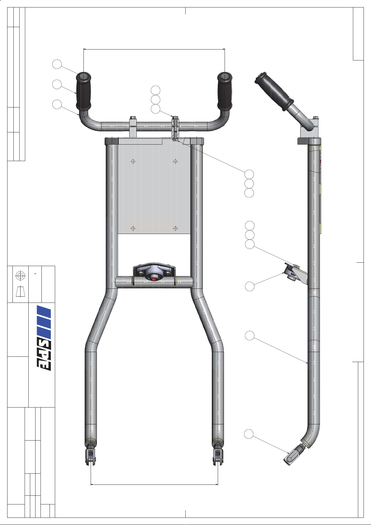
HANDLE ASSEMBLY
ITEM
QTY
PART NUMBER
DESCRIPTION
1
2
9122
Yoke & Clevis Pin
2
1
5502
Handle Assembly
3
2
5516
Handle Clamp
4
2
5516
Handle Clamp
5
1
5517
Handle Bar
6
1
9134
Bearing
7
2
9104
Hand Grip
8
2
TI/011
Tube End
9
4
BOLT045
M8 x 35 Set Screw
10
2
BOLT043
M8 x 25 Set Screw
11
4
BOLT042
M8 x 20 Set Screw
12
2
NUT044
M8 Nyloc Nut
13
12
WASHER004
M8 Flat Washer
17
This manual suits for next models
1
Table of contents
Other SPE Floor Machine manuals


