Speakman T-5001 User manual

800-537-2107 www.speakman.com
NEED HELP?
For additional assistance or service please contact:
INSTALLATION INSTRUCTIONS
T-5001
T-6000
One-Piece Toilet
92-T-6000-05
TOOLS & SUPPLIES NEEDED IMPORTANT
MAINTENANCE:
Your new Speakman Product is designed for
years of trouble-free performance. Keep it
looking new by cleaning it periodically with a
soft cloth. Avoid abrasive cleaners, steel wool,
and harsh chemicals as these will dull the finish
and void your warranty.
Your new Speakman Toilet includes a premium
fill valve with an internal filter designed to trap
impurities allowing for reliable operation of the
fill valve. Periodic removal and cleaning of the
filter is recommended for optimal performance.
Please see the “Fill Valve Filter Cleaning”
section of this document for more information.
SAFETY TIPS:
Be sure to read and understand all instructions
before beginning installation.
Inspect all connections after installation.
Be sure to wear proper eye protection.
NOTE:
This installation manual covers several
models of Toilets. While the appearance of your
Toilet may differ from those shown, the
installation method is the same.
WARNING
DO NOT OVER-TIGHTEN
CONNECTIONS OR DAMAGE MAY
OCCUR.
DO NOT USE CHLORINE OR ANY
CHEMICALLY RELATED
COMPONENTS AS THIS WILL
RESULT IN DAMAGE TO TANK
COMPONENTS AND MAY CAUSE
FLOODING AND PROPERTY
DAMAGE.
USE OF CHLORINE OR
CHEMICALLY RELATED
COMPONENTS WILL VOID
WARRANTY.
Phillips
Screwdriver
Adjustable
Wrench Level
Measuring
Tape
Supply Hose with
7/8” Ballcock End
VERIFY ROUGH-IN
1For your Toilet to fit correctly, the rough-in distance between the finished wall to the center of the
Closet Flange must be at least 12”
Finished
Wall
Water
Supply
Valve
12”
Closet
Flange
INSTALL SUPPLY LINE TO TOILET
2From behind, position the Supply Line up through the opening in Bowl. Connect the water supply
line to the fill valve threads as seen at the bottom of toilet tank. Tighten the connection.
CAUTION: Do not over-tighten or damage may occur.
3
INSTALL TOILET SEAT
Install the Toilet Seat using the
instructions included within the Toilet
Seat packaging. Mounting the Seat now
will allow easier access to Toilet Seat
Mounting Hardware prior to mounting the
Toilet to the Closet Flange.
4
CLOSET BOLT INSTALL
Clean any debris out of the Closet Flange and then install new Closet Bolts into the slots of the
Closet Flange. The head of the bolt should be inserted into the slot with its threads facing upward
as shown. Once the Closet Bolts are located properly, secure into position with a Washer and
Square Nut. Wrench tighten.
5
WAX RING INSTALL
Carefully lay to Toilet onto some padding.
Firmly press a Bowl Wax Ring onto the
circular recess around the Toilet Bowl’s
Horn.

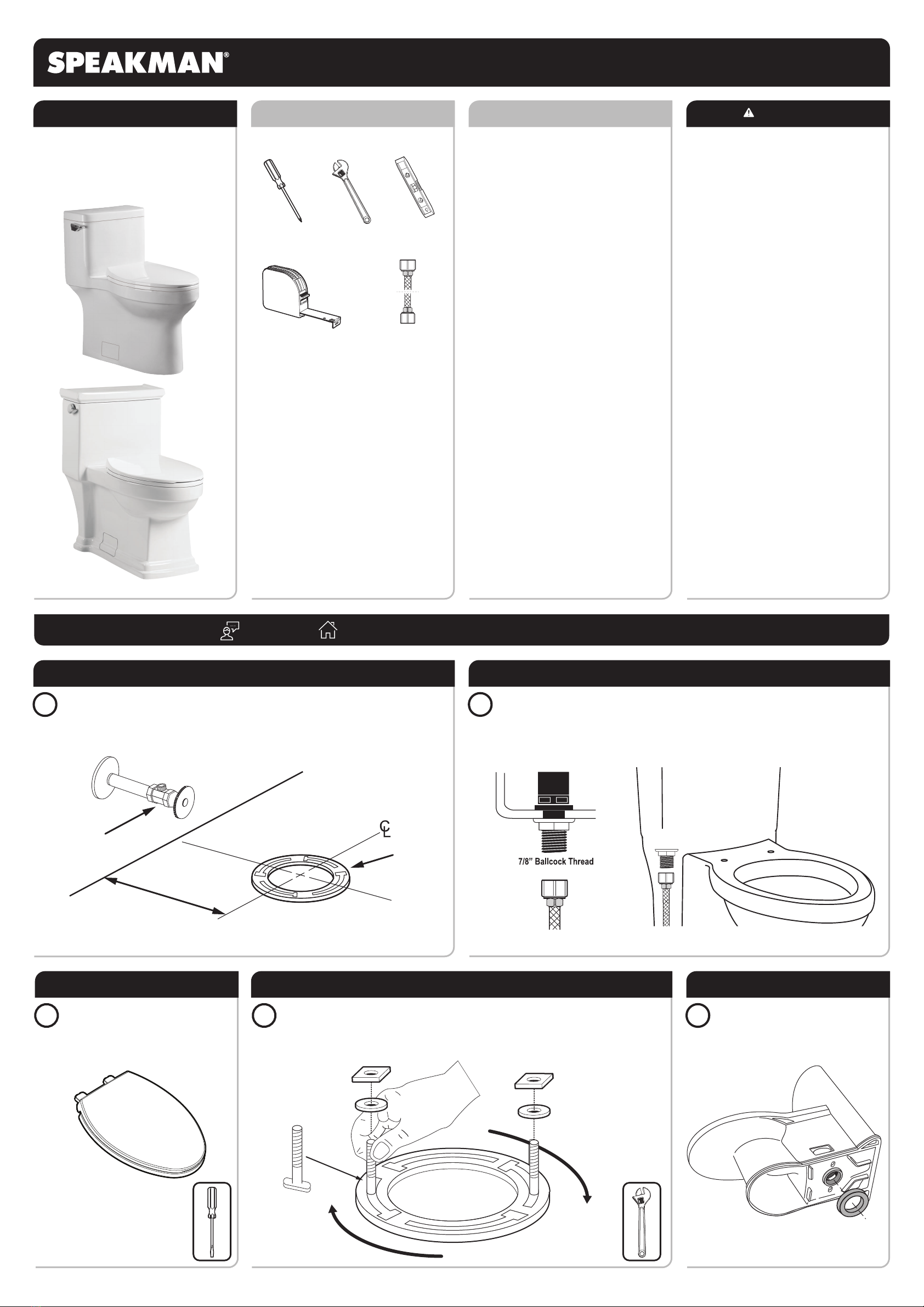
POSITION TOILET ONTO WAX RING
6Turn the Toilet upright and gently lower into position over the Closet Flange and Closet Bolts. With
the Toilet properly aligned, firmly press on both sides of Toilet Rim to set the Bowl Wax Ring.
Ensure Toilet is properly aligned.
CAUTION: Do not over-tighten or damage may occur.
SECURE BOWL INTO POSITION
7CAUTION: Do not move the Bowl after
the Bowl Wax Ring is set.
Position a Flat Washer over the Closet
Bolt. Secure into position with a Brass
Acorn Nut. Tighten evenly until the Bowl
is snug to the Closet Flange.
8
COVER PLATE INSTALL
Install Cover Plates over Closet Bolt
Access Panel.
3/8” COMPRESSION
9/16”-24 UNEF
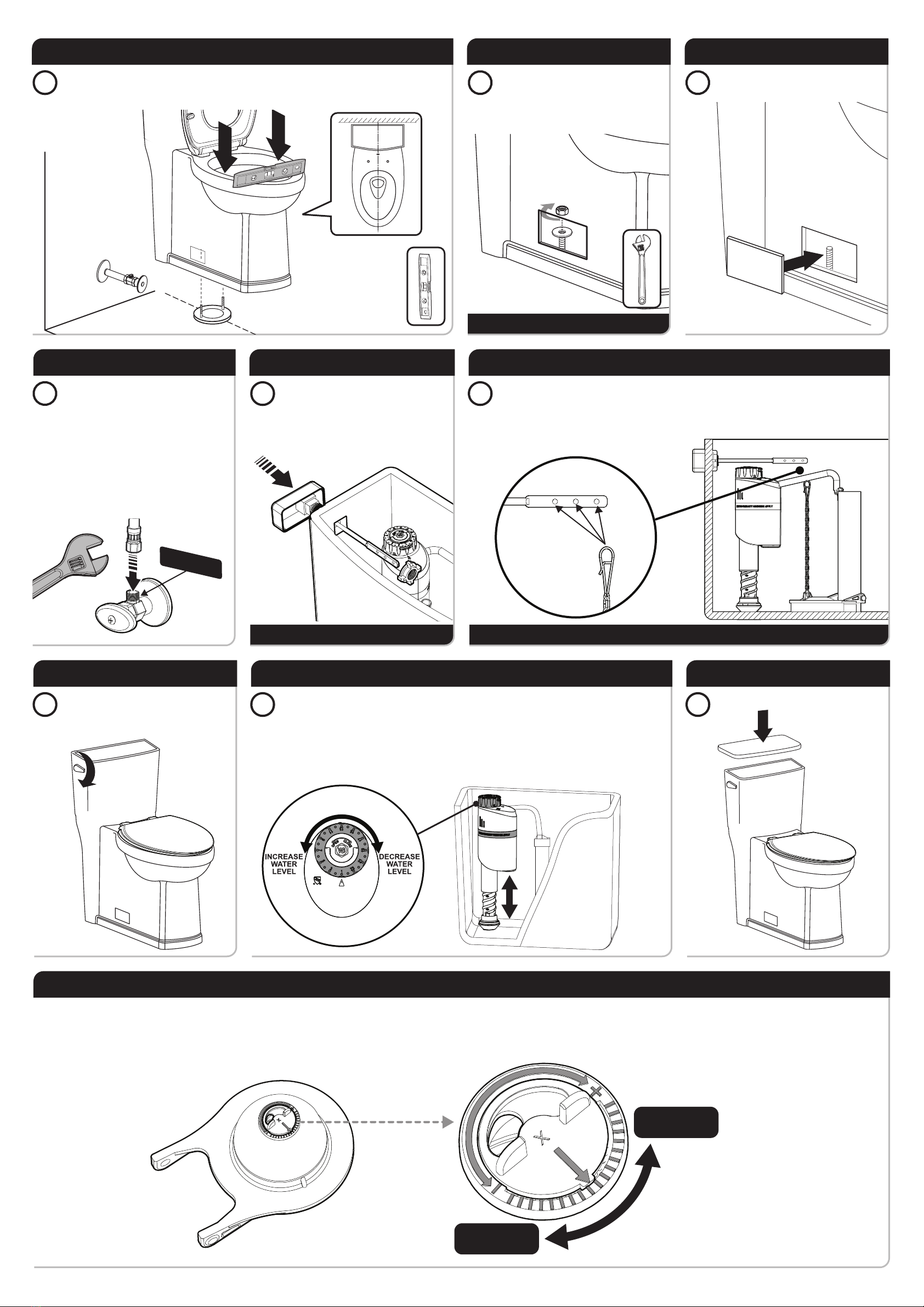
CONNECT TO WATER SUPPLY
9
Flush the water supply line for a few
seconds to remove any debris that may
enter the Fill Valve. (For new home
constructions and/or additions, flush the
water supply line for more than a minute
to help remove any residual PVC
adhesives, solder flux, and/ or pipe
sealants that were used for the new
plumbing.)
Install the Supply Line to the Supply Stop.
Wrench tighten into position. Turn ON the
Supply Stop.
CAUTION: Do not over-tighten or damage may occur.
VERIFY HANDLE INSTALLATION
10
Position the Handle through the opening
in the side of the Tank with the Trip Lever
facing forward. The square post on the
Handle stem should align with the square
opening within the Tank as shown below.
Secure into position with the included
Nut. Hand tighten.
CAUTION: Remove the Tape securing the Flapper in position if present.
VERIFY PROPER CHAIN LENGTH
11
Attach the Chain from the Flapper to one of the corresponding holes within the Handle Lever.
When correctly installed the Flapper should fully seal against the Flush Valve when the Handle is
in the resting position, yet open appropriately when the Handle is activated to flush the Toilet.
Additional adjustments to the length of the Chain may be required to achieve this.
12
TEST FLUSH
Flush toilet a few times to check for
issues and leaks. Make sure there are
NO WATER LEAKS.
WATER LEVEL ADJUSTMENT
13
The Fill Valve is factory pre-set. If adjustments are required:
To increase the water level, turn the Rotating Dial counterclockwise while holding the body of the
Fill Valve to prevent any unnecessary movement.
To decrease the water level, turn the Rotating Dial clockwise while holding the body of Fill Valve
to prevent any unnecessary movement.
There are 24 marked dots on the Rotating Dial. Each dot represents a level of adjustment in
regards to the water level in tank.
14
TANK LID INSTALL
Place the Tank Lid onto the Tank.
LESS WATER
PER FLUSH
MORE WATER
PER FLUSH
FLAPPER ADJUSTMENT
This Toilet includes an Adjustable Flapper that allows the installer to adjust the volume of water used per flush. This Adjustable Flapper comes pre-adjusted to use 1.28 gallons / 4.8 liters per
flush. If your installation requires a different volume of water per flush, access the underside of the Adjustable Flapper and rotate the adjustment wheel towards the minus symbol (-) for
MORE water used per flush, or towards the plus symbol (+) for LESS water used per flush.

1
B
C
OFF
A
Turn OFF water supplies (A). Lift handle of
Filter (B). Rotate Filter counter-clockwise
while holding the Rotational Dial stationary
(C).
2Once Filter is released, pull upward to
remove from the Fill Valve. 3Clean Filter by rinsing under running water. 4
A
B
ON
C
MAINTENANCE: FILL VALVE FILTER CLEANING
Insert the Filter into the Fill Valve while
aligning the Tabs (A). Rotate Filter
clockwise while holding the Rotational Dial
stationary until Filter locks into position
(B). Turn ON water supplies (C).
TROUBLESHOOTING
Issue: Water surface is too high or too low
Cause: Inlet Valve is not adjusted to the desired position.
Solution: Adjust water level by following the “Water Level Adjustment” section.
Issue: Inlet Valve does not turn on
Cause: Water Supply is off.
Solution: Turn on Water Supply. If Fill Valve is still not functional, turn off Water
Supply and clean Filter Screen by following the “Filter Cleaning” section
in this manual.
Issue: Inlet Valve does not turn off
Cause: Refill Tube wasn’t installed properly.
Solution: Re-install the Refill Tube by following Step 4 of the “Fill Valve Install”
section.
PRODUCT WARRANTY
Speakman will, at its election, repair, replace, or make appropriate adjustment where Speakman's inspection discloses any
such defects occurring in normal usage. Damage caused by accident, misuse, or abuse is not covered by this warranty.
Improper care and cleaning will void the warranty. Use of Chlorine or chemically related components will void the
warranty. Proof of purchase (original sales receipt) must be provided to Speakman with all warranty claims. Speakman is
not responsible for removal, installation, labor charges, or other incidental or consequential costs. In no event shall the
liability of Speakman exceed the purchase price of the toilet.
*Mechanical Component Limited Warranty varies based on component affected. Please call 1-800-537-2107 for additional information.
CALIFORNIA PROPOSITION 65
CALIFORNIA PROPOSITION 65:
WARNING: This product can expose you to chemicals including lead, which is known to
the State of California to cause cancer and birth defects or other reproductive harm. For
more information go to www.P65Warnings.ca.gov
Wash hands after installation, repair, or removal of this product.
COMPLIANCE
CONNECTIONS
ASME A112.19.2/CSA B45.1
cUPC certified
WaterSense certified
ADA compliant
3/8” Compression (Inlet Hose Connection - Included)
12” Rough-In to wall
T-5001 ROUGH-IN DIAGRAM
WALL
28-3/8” (720mm)
18-1/2” (470mm)
16-1/2”
(420mm)
12”
(305mm)
28-3/4”
(730mm)
16-3/8” (415mm)
SUPPLY
AS
REQ’D
8-5/8”
(220mm)
6”
(152mm)
COMPLIANCE
CONNECTIONS
ASME A112.19.2/CSA B45.1
cUPC certified
WaterSense certified
ADA compliant
3/8” Compression (Inlet Hose Connection - Included)
12” Rough-In to wall
T-6000 ROUGH-IN DIAGRAM
WALL
28-3/4” (730mm)
18-1/2” (470mm)
16-1/8”
(410mm)
12”
(305mm)
29-1/2”
(750mm)
18-1/8”(460mm)
SUPPLY
AS
REQ’D
8-5/8”
(220mm)
6”
(152mm)

REPAIR PARTS
87751
Finale ProSeries
Fill Valve with Brass Shank
39743
3” Flush Valve
with Adjustable Flapper
85532
Elongated
Slow-Close Toilet Seat
39744
3” Adjustable Flapper 59449W
Brass Closet Bolt Set
57665
16” Toilet Supply Line
51499
Wax Bowl Gasket
39747
Replacement Tank Lid
for Model # T-5001
39712
Porcelain Closet Bolt Cover Plate Pair
for Model # T-5001
39714
Porcelain Closet Bolt Cover Plate Pair
for Model # T-6000
39748
Replacement Tank Lid
for Model # T-6000
39749
Replacement Flush Handle
This manual suits for next models
1
Other Speakman Toilet manuals
Popular Toilet manuals by other brands

Toto
Toto Washlet C200 Connect+ Series manual

Geberit
Geberit AquaClean 8000 installation manual

noken
noken CITY 100235046 N399999686 manual

DURAVIT
DURAVIT SensoWash Starck f Lite operating instructions

American Standard
American Standard Champion PRO 211AA Series INSTALLATION INSTRUCTIONS CARE AND MAINTENANCE

Geberit
Geberit AquaClean Mera Comfort 146.210.11.1 installation manual