Specac Golden Gate GS10500 Series User manual

Quick Start Guide For Golden Gate™ ATR
Accessory P/N GS10500 Series
This Quick Start Guide is intended to help you through the steps required for the correct first time installation and
alignment of the Golden Gate™ ATR Accessory into your IR spectrometer system. This guide is a supplement to
the Instruction Manual provided for the accessory itself where more detailed information can e found.
Step 1 – nstall the Benchmark™ Baseplate into your spectrometer
The Benchmark™ aseplate supplied allows the Golden Gate™ ATR Accessory to e
positioned correctly in the sample compartment of your specific spectrometer.
Please consult the relevant page of the Benchmark™ Baseplate Installation Guide
instruction manual (2I-549-000-7) if you need more information.
Step 2 – Fit the Golden Gate™ ATR Top Plate to the Optical Unit
For any Golden Gate™ ATR Accessory that is supplied, the ATR crystal
Top Plate assem ly of choice (with diamond or germanium crystal option)
will normally already e fitted to the Optical Unit. If these parts are separate,
install the Top Plate onto the Optical unit using the two fixing thum s screws.
(The Top Plate will only fit to the Optical Unit one way evenly and flat
with the stud and pin fix fixings on the Optical Unit passing correctly
through the slot and circular holes on the Top Plate.)
Step 3 – Fit the Golden Gate ATR Accessory (Optical Unit) to the Baseplate
The Golden Gate™ ATR Accessory can now e fitted onto the
Benchmark™ aseplate. The Optical Unit is placed over the
aseplate support pillars and the fixing thum screw is
tightened into the central front pillar.
F
ixing Thumb
Sc
rew
of
Optical Unit to
Benchmark™ Baseplate
Top Plate
Fixing
Thumb Screws
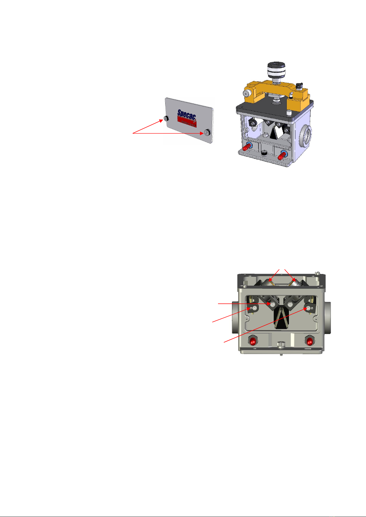
Step 4 – Remove the Front Cover of the Optical Unit
Undo the two captive screws on the front
cover plate of the Optical Unit and pull the
cover plate clear to gain access to the mirrors
and lens optical components for alignment.
Step 5 – Alignment Procedure
With the spectrometer in its energy monitoring mode, use the 3.0mm all driver (for rotation) and 2.0mm Allen key
(for tilt) tools supplied to adjust the alignment screws of the mirrors and lens assem lies in the Optical Unit. It is
important to know the source to detector eam direction of the spectrometer eing used - left to right or right to left –
as it passes through the sample compartment. This determines the input mirror and lens to the sample area and
output mirror and lens from the sample area to adjust.
For alignment start with the output adjusta le mirror for its rotate and then tilt position y turning of the respective
adjustment screws. O tain a maximum energy reading with a rotational adjustment of the mirror efore moving to the
tilt adjustment and then o tain a maximum reading from the tilt adjustment. Then adjust the focus position of the
output lens. The lens arrel locking screw is loosened y the 3.0mm all driver and the lens assem ly is slid in its
mount for focus holding the little tiller ar. When a maximum throughput is o tained from the output lens focal point
lock the screw again.
Repeat the rotate, tilt and focal point adjustment settings ut for the input
mirror and lens components to try and maximise the throughput. If the
energy has increased significantly after these adjustments for the input
mirror and lens components then repeat them again in the same order ut
for the output components once again only. This will ensure that the
accessory is at its optimum alignment settings.
Remem er, this alignment process only has to e
done once when first setting up the accessory in
the spectrometer – so it is worth spending a small
amount of time now in order to get the est
performance from it in the future.
Step 6 – Replace the Front Cover
Once aligned, the front cover can e replaced to maintain a sta le environment inside the accessory. To fit the purge
ellows or a dry air supply to purge the accessory, refer to page 23 of the Golden Gate™ ATR Accessory instruction
manual provided.
Step 7 – t’s Ready to Use!
For safety information and detailed instructions on getting the est from your Golden Gate™ ATR accessory please
refer to the Golden Gate ™ ATR Accessory instruction manual 2I-10500-17 supplied.
Specac Ltd
River House, 97 Cray Avenue,
Orpington
Kent BR5 4HE
Tel: +44 (0) 1689 873134
Fax: +44 (0) 1689 878527
www.specac.com
QS-10500-3
Captive
Screws
Front Cover Plate
Removed
L
ens Assembly
L
ens Assembly
Locking Screw
Mirror Tilt
Grub Screw
Mirror Rotation
Cap Head Screw
Other manuals for Golden Gate GS10500 Series
1
This manual suits for next models
1
Table of contents
Other Specac Industrial Equipment manuals


