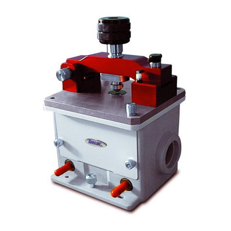
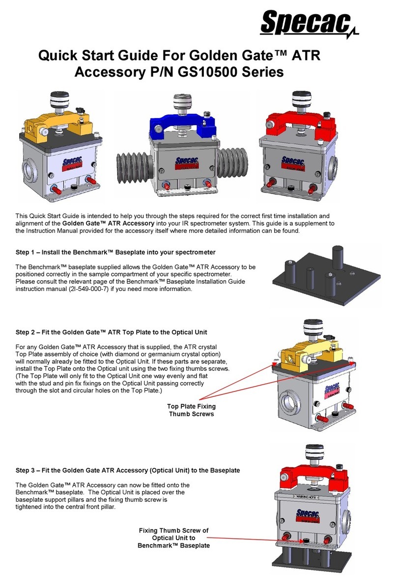
Specac Golden Gate User manual

Low Temperature
Golden GateTM Diamond ATR System
User Manual
2I-10590 Issue 10

2
List of Safety Symbols
Safety Symbol
ISO 7000 symbol m
eaning
CAUTION!
WARNING – Hot Surface
(Reference ISO 7010-W017)
For indoor use only
(Reference IEC 60417-5957)
WARNING – Low Temperature/Freezing
conditions
(Reference ISO 7010-W010)
CAUTION! Only use the configured temperature controller
supplied with this accessory.
CAUTION! This user instruction manual should be read in
conjunction with the temperature controller and Golden
Gatetm manuals provided separately with the respective
Specac accessory.

3
Low Temperature
Golden Gate™ Diamond ATR
User Manual
2I-10590 Issue 10

User Manual
4
Low Temperature Golden Gate™ Diamond ATR
Models GS10590 / GS10592
USER MANUAL
1. INTRODUCTION 5
2. PACKING AND CHECKLIST 5
3. SAFETY OF USE 6
4. INSTALLATION 7
FIXING OF P/N GS10590 TOP PLATE 8
5. OPERATION OF THE LOW TEMPERATURE GOLDEN GATE™
ATR TOP PLATE 11
IMPORTANT NOTE FOR OPERATION 11
DEWAR CAP (10) NITROGEN PURGE CONNECTION 11
REFRIGERANTS TO USE 13
PREPARATION FOR USE AND GENERAL OPERATION 14
PROCEDURE USING A HIGH THERMAL TRANSFER GASKET 15
OTHER EXAMPLES OF OPERATION 18
1) USE OF LIQUID NITROGEN TO -80°C 18
LIQUID SAMPLES 19
SOLID SAMPLES 23
2) USE OF CARDICE (DRY CO2) AND ACETONE AS
REFRIGERANT AT -30°C 24
6. OPERATING PARAMETERS FOR THE LOW TEMPERATURE
GOLDEN GATE™ ATR TOP PLATE 25
7. LEGEND - PART IDENTIFICATION OF LOW TEMPERATURE
GOLDEN GATE™ TOP PLATE 27
8. SPARE PARTS FOR LOW TEMPERATURE GOLDEN GATE
TOP PLATE 28
© April 2016 Specac Ltd. All rights reserved.
Golden Gate™ and Brilliant Spectroscopy™ are trademarks of
Specac Ltd. Other product names mentioned herein may be
trademarks of their respective owners.

Low Temperature Golden Gate™ ATR
5
1. Introduction
Thank you for purchasing a Specac Product.
The Low Temperature Golden Gate™ single reflection diamond ATR
top plate is designed for use on the Golden Gate™ ATR optical base
unit. It is used to study liquid or solid samples at temperatures from
minus 150C to +80C. Liquid samples are analyzed by simply
covering the diamond ATR crystal, and the standard Golden Gate
clamp bridge is used to provide pressure for solid samples, providing
excellent sample contact.
Fig 1. Sectional Front View of Low Temperature ATR
2 6
4
5
3
1
4

User Manual
6
Golden Gate™ Top Plate
The analysis area of the top plate is a heatable diamond crystal
bonded into a tungsten carbide support disk (1), surrounded by a
cooling jacket dewar assembly (2). The dewar assembly is clamped to
the heated diamond ATR top plate (3) by four clamping screws (4).
There is a heat transfer gasket (5) between the diamond/ tungsten
carbide disk (1) and the centre part of the dewar (2). (Please see Figs
1 and 2.)
Fig 2. Diamond/Tungsten Carbide Puck and Gasket detail area of
Low Temperature Golden Gate™ Top Plate
Using liquid nitrogen as an example refrigerant in the dewar chamber
(6) and from control of power to the heaters, temperatures below
ambient can be achieved. For temperatures above ambient, no
refrigerant is required and the heaters for the diamond crystal are used
alone. Power to the heaters is provided by a dedicated 4000 Series
Temperature Controller. A separate instruction manual is provided for
operation of the Temperature Controller with the Low Temperature
Golden Gate™ ATR top plate.
2 5
3
1

Low Temperature Golden Gate™ ATR
7
2. Packing and Checklist
On receipt of your Low Temperature Golden Gate™ ATR accessory
please check that the following have been provided.
Low Temperature Golden Gate™ single reflection diamond ATR
top-plate (P/N GS10590).
Golden Gate Optical unit with choice of ZnSe or KRS-5 lenses and
appropriate Benchmark baseplate (if ordered as a complete
Golden Gate system (P/N GS10592)).
4000 Series Temperature Controller, instruction manual and power
cables.
Flat “transfer load” anvil to sapphire tipped rod assembly.
Sapphire tipped rod assembly.
Liquid sample injector consisting of an insulated 16-gauge
hypodermic needle and glass syringe.
Plastic funnel
Allen key (2mm).
Allen key (3mm).
Hex head ball driver (3mm).
Long T bar type Allen key (5mm).
Packet of glass filled PTFE gaskets (5).
Packet of high thermal transfer gaskets (20)
Spare Viton ‘O’ ring seal.
An Essential Spares Kit of parts (P/N GS10550)
Carefully remove the equipment from their packaging and proceed to
install into your spectrometer system.

User Manual
8
3. Safety of Use
WARNING – Low Temperature / Freezing conditions
The Low Temperature Golden Gate™ ATR system requires the use of
liquid nitrogen (LN2) for operation at sub ambient temperatures. When
using refrigerants, ensure all local laboratory safety procedures are
followed and wear appropriate personal protective equipment (PPE).
Recommended PPE gloves and glasses should be worn at all times
when operating this equipment.
Always use a suitable plastic funnel assembly for filling of the dewar
with liquid refrigerant to avoid accidental spillage to other areas of the
equipment. The funnel supplied (7) can be used either for introduction
of a liquid refrigerant through the small hole (8) or the crescent shaped
cut out (9) in the dewar cap (10). (See Fig 2).
Fig 2. Dewar Cap and Funnel Parts of Low Temperature Golden
Gate™ ATR Accessory
7
10
9
8

Low Temperature Golden Gate™ ATR
9
CAUTION! It is important to read any associated safety
information in the accessory manual before operating this
equipment.
Caution: Always follow local laboratory safety protocols
and procedures when using potential toxic or flammable
substances with this equipment. The equipment is
intended for use by suitably trained personnel only.
Caution: If the equipment is used in a manner not
specified within this manual, the protection provided by
the equipment may be impaired
Only clean with a soft, lightly dampened cloth. Do not use harsh
and/or abrasive cleaners on any Specac product. Consult Specac or
their authorized agent if in any doubt.
Always check before use that the safety protection provided have not
been compromised or impaired. The temperature controller should be
made inoperative and secured against unintended operation if in any
doubt.
The protection is likely to be impaired if for example if:
• Shows visible damage.
• Fails to perform its intended use.
• Has been subjected to adverse storage conditions.
• Has been subjected to severe transport stresses.
End of Lifetime Equipment Use
If any parts have reached their limit of lifetime and need to
be replaced, use appropriate WEEE and other local
regulations for the safe disposal of electrical equipment
and toxic chemicals.

User Manual
10
4. Installation
For the Low Temperature Golden Gate™ ATR system, P/N GS10592
the system is fully assembled before shipping (See Fig.3).
Fig 3. Low Temperature Golden Gate™ ATR System
Once installed into the host spectrometer, connect the heater and
thermocouple cables to the 4000 Series Temperature Controller (Not
shown). Refer to the 4000 Series 150W temperature controller
instruction manual for further details.
10
4
11
13
14
2

Low Temperature Golden Gate™ ATR
11
For Low Temperature Golden Gate™ ATR top plate upgrade (P/N
GS10590), the heated top plate is attached to the dewar assembly
before shipment. The dewar assembly and will need to be separated
from the heated top plate to enable fitment of the Golden Gate™
optical unit. The dewar assembly is then re-installed to complete the
assembly.
Fig 4. Separation of Low Temperature Golden Gate™ Dewar
Assembly from Heated Top Plate and Optical Unit Assembly
Remove the dewar assembly fixing screws (4) (See Fig 4.) using the
long T bar type Allen Key (5mm) allowing separation of the dewar from
the Golden Gate™ heated top plate.
2
4
11
3 5

User Manual
12
The heated top plate assembly (3) attaches to the Golden Gate™
optical unit (11) with the two new M4 x 16mm screws (12) supplied
(See Fig 5.). The new screws replace of the original thumb screws and
are shorter in length to allow the fixing of the dewar assembly to the
flat stainless steel heated top plate (Refer to P/N GS10500 Golden
Gate™ instruction manual for further details).
Fig 5. Low Temperature Golden Gate™ Heated Top Plate
and Optical Unit
When the heated top plate assembly (3) has been fitted to Golden
Gate™ optical unit (11) with the two M4 x 16mm screws (12), the cold
dewar assembly (2) can be re-fitted using the four fixing screws (4).
When tightening down the dewar fixing screws (4) ensure that the two
surfaces between the cold dewar assembly (2) and heated top plate
(3) remain parallel and even to ensure the correct thermal contact and
sealing of the thermal transfer gasket (5) between the dewar assembly
(2) and the diamond tungsten carbide puck (1).
3
11
5
12

Low Temperature Golden Gate™ ATR
13
Caution! Before tightening the dewar assembly to the heated top plate
assembly ensure that the correct thermal transfer gasket (5) (choice of
a white glass filled PTFE or grey graphite gasket) has been placed
correctly into position over the diamond/tungsten carbide puck. In
addition, ensure the gasket (5) does not get dislodged and cover /
obscure the diamond crystal while fitting the dewar assembly (2) over
the heated top plate assembly (3).
Additional Information:
When conducting the alignment procedure on the optical components
(mirrors and lenses) within the Golden Gate™ optical unit, ensure that
the cold dewar assembly (2) and the thermal transfer gasket (5) has
been tightened/screwed down correctly to the heated top plate
assembly (11). The diamond/puck assembly (1) has been designed to
be supported under sprung loaded tension and may move slightly
when the cold dewar assembly (2) is placed into position. Therefore,
optimum light beam throughput is achieved when the cold dewar
assembly (2) is fixed correctly in the working position over the diamond
(1). See alignment procedure in the Golden Gate™ instruction manual
P/N GS10500 for further details.
When the Low Temperature Golden Gate™ ATR Accessory has been
supplied under P/N GS10592, a white glass filled PTFE thermal gasket
(5) fitted by default.

User Manual
14
5. Operation of the Low Temperature Golden
Gate™ ATR Top Plate
Important Note for Operation
When using the Low Temperature Golden Gate™ ATR accessory at
temperatures below the ambient dew point, it is essential to use and
establish a nitrogen purge within the Golden Gate™ optical unit (11)
before any refrigerant is poured into the dewar chamber (6). This is to
prevent condensation or frost forming on the internal optics of the
Golden Gate™ optical unit. The purge can be established by using a
spectrometers own purge facility (if available) by using the purge
bellows (P/N GS10707) to bridge the gap between the Golden Gate™
apertures (13) and the input and output ports of the Spectrometer.
(See Purging the Golden Gate in the P/N GS10500 manual.)
Alternatively, with the purge bellows fitted to the aperture ports (13),
the optical unit (11) can be purged via the two, purge port hose
connectors (14) on the front of the Golden Gate™ optical unit (11)
using a dedicated dry nitrogen gas supply. (See Fig 3.)
Dewar Cap (10) Nitrogen Purge Connections
A nitrogen purge that is required to prevent frosting of the optical
components in the Golden Gate™ optical unit (11) during low
temperature operation is also needed for the central internal area of
the dewar assembly (15) above the diamond/tungsten carbide puck (1)
when taking reference background spectra for sub-ambient
temperature conditions. See Fig 6.
When the dewar cap (10) is placed into position, to cover the dewar
chamber (6), a supply of nitrogen gas can be introduced through one
of the 3.5mm diameter purge gas flow holes (16) in the dewar cap (10).
Similar to the optical unit (11) gas purge requirement, a purge gas
though the dewar cap (10) must be established before introduction of
any refrigerant. The inner chamber area (15) below the cap (10) will be
filled with the nitrogen gas and a flow of the gas will minimize any risk

Low Temperature Golden Gate™ ATR
15
of condensation forming and possibly freezing to the surface of the
diamond ATR crystal. See Fig 7.
Fig 6. Low Temperature Golden Gate™ Dewar area with
Dewar Cap removed. (Inner and Outer Dewar Chambers)
Fig 7. Low Temperature Golden Gate™ Dewar Cap Purge Holes
6
15
16

User Manual
16
CAUTION! Use of alternative refrigerants
The minimum recommended operating temperature is -150°C when
used in combination with liquid nitrogen (LN2) and the graphite high
thermal transfer gasket. Other types of refrigerant mixture are listed in
the table below.
Table of Refrigerant types
Refrigerant Type
Mixed Temperature
(a)
Main Hazard
C
K
Ice Water 0 273 Cold surfaces
Sodium Chloride/Ice (33g salt/81g ice) -21 252 Cold surfaces
Calcium Chloride/Ice (100g salt/81g ice) -40 233 Cold surfaces
Chloroform/Liquid Nitrogen (slush)
-64 209 Cold surfaces
(b)Solid CO2/Ether -78 195 Fire/Explosion
(b)Solid CO2/Acetone -78 195 Fire/Explosion
(b)Solid CO2/Isopropanol -78 195 Fire/Explosion
(b)
Toluene/Liquid Nitrogen (slush)
-95 178 Fire/Explosion
(b)
Pentane/Liquid Nitrogen (slush) -130 143 Fire/Explosion
Liquid Air (<21% oxygen)
-147 126 Cold surfaces
(b)
Isopentane/Liquid Nitrogen (slush) -160 113 Fire/Explosion
(b)Liquid Oxygen -182 91 Fire/Explosion
Liquid Nitrogen (LN2) -196 77 Cold surfaces,
Asphyxiation
(a) These figures are approximate as actual mixture temperatures are
affected by impurities.
(b) Appropriate safety risk assessments and laboratory procedures
need to be implemented before use of other alternative refrigerants.

Low Temperature Golden Gate™ ATR
17
For optimum temperature control in operation, you should choose the
refrigerant mix closest to the temperature you wish to study. From the
examples above, the natural freezing point of LN2 is -196°C, but the
lowest temperature achievable for the system overall is -150°C using
this refrigerant with an appropriate grey coloured graphite high thermal
transfer gasket (5). It will be a matter of experimentation for the best
choice of a refrigerant and gasket (5) combination, depending upon the
minimum and maximum temperatures to be achieved and the
temperature degree of control required.
In general, for temperature operation between -100°C and -150°C the
high thermal transfer graphite gasket (5) must be used. This gasket
material allows for these low temperatures to be reached but does not
have the same degree of temperature control offered by the low
thermal transfer white PTFE gasket (5).
For temperature operation between ambient and -100°C the low
thermal transfer white PTFE gasket (5) should be used, if a finer
degree of temperature control and thermal stability is required.
Preparation for Use and General Operation
The successful use of the Low Temperature Golden Gate™ ATR
accessory depends on the correct balancing of a specific refrigerants
“heat removing” capability against the energy (heat) input from the
electrical block heaters (17), built into the heated top plate assembly
(3) at the base of the dewar assembly (2). See Fig 8. The type of
experiment being carried out also determines a method of use and,
most importantly, the choice of thermal transfer gasket (5) between the
dewar assembly (2) and the diamond/tungsten carbide puck (1).
Note: In any experiment it is advisable to take a reference background
Spectrum (or spectra) at the same actual temperature
conditions when collecting a spectrum (or spectra) for the
sample. This is to obtain the optimum spectral results when the
background spectrum is subtracted from the sample spectrum.

User Manual
18
Fig 8. Low Temperature Golden Gate™ Heated Top Plate
Assembly underside view
If it is a requirement to obtain spectra for a sample at two different
physical states, solid and liquid, depending upon the freezing point of a
liquid sample it may be preferable to use the graphite high thermal
transfer gasket (5) in position. This gasket material will permit
operation down to the minimum temperature obtainable with this
accessory to -150ºC. By using this high thermal transfer gasket (5) the
sample can be quickly frozen using only a small amount of LN2
refrigerant, allowing it to boil off as soon as the desired temperature is
reached. This will minimize condensation and icing on the dewar (2).
Procedure Using a High Thermal Transfer Gasket
To ensure freezing of the LN2 refrigerants lowest temperature
capability (circa -150°C with a graphite high thermal transfer gasket (5)
being used), the block heaters (17) must be switched off by selecting a
lower set temperature on the controller (e.g. at least 10°C less than the
value showing for any actual temperature from the LN2 refrigerants
cooling action). Therefore, a suggested set temperature at the start of
experimentation is -150°C on the controller, as the accessory overall
will never get colder than this temperature value.
17
3

Low Temperature Golden Gate™ ATR
19
Reference Spectrum Collection
For collection of a background reference spectrum, at room
temperature conditions, establish the nitrogen purge gas conditions in
the optical unit (11) and within the internal sample chamber area (15)
from connection of the purge gas via a suitable flow pipe or tubing
through one of the dewar cap purge gas holes (16), before any
refrigerant is added.
Introduce some LN2 into the dewar chamber (6) using the funnel (7)
through the funnel hole (8) or crescent shaped cut out (9) in the dewar
cap (10). Initially, there will be some fuming of the LN2 as it boils off
when contacting with a warmer environment, but by adding small
amounts of LN2, after time the actual temperature on the controller
display will begin to drop fairly, quickly indicating the effect of the LN2
refrigerant action to the sample area for temperature measurement.
When the actual temperature has dropped to a value that is to be used
for study, stop adding any further LN2 refrigerant. If only small
amounts of LN2 have been added, once the remaining residual LN2
has boiled off from the dewar chamber (6), and because the heaters
(17) will still be inactive as the actual temperature will be higher than
the set temperature (-150°C), the accessory will start to warm up
naturally from the general ambient surroundings. At this stage when
the temperature value becomes relatively stable, a background ATR
spectrum can be collected and stored for use against an ATR
spectrum taken for a sample at the same temperature and conditions
of use.
If the refrigerant effect of the LN2 in combination with a high thermal
transfer graphite gasket (5) is causing the temperature to be too low in
value, (i.e. towards the minimum -150°C value), then the heaters (17)
may need to be activated to balance the cooling effect and raise the
temperature to the value desired. Therefore, if say a temperature of
-100°C is required, change the set temperature value to -100°C on the
controller. If the actual temperature is indicating a temperature value
lower than -100°C, the heaters (17) will activate (the heater light pulses
on the controller display) and the temperature will rise.

User Manual
20
Note: It is important for this type operation at very low temperatures to
ensure the LN2 refrigerant level is kept topped up to provide the
“balancing effect” against the power from the heaters (15).
Sample Spectrum Collection
When a reference spectrum at a particular low temperature value has
been collected the procedure of operation needs to be repeated, but
with some subtle changes.
To place a sample into position on the diamond crystal (1) after
collection of a reference spectrum, the Low Temperature Golden
Gate™ ATR accessory must be allowed to warm up to ambient
conditions. When the accessory is near to, or has reached room
temperature, dry off any external condensation using tissues. It may be
easier to dry the unit thoroughly by disconnecting the 4000 Series
Temperature Controller and removing the Low Temperature Golden
Gate™ accessory from the spectrometer and to place it on a
workbench.
When cleaned and dried, and re-installed in the spectrometer, at room
temperature conditions establish the nitrogen purge gas conditions in
the optical unit (11) and within the internal sample chamber area (15),
before any refrigerant is added, a liquid sample is placed in position to
cover the diamond of the diamond/tungsten carbide puck (1). Included
with the accessory is a liquid sample injector consisting of an insulated
16 gauge hypodermic needle and glass syringe that can be used for
delivery of a liquid sample at the base of the internal chamber area
(16) and over the diamond (1).
When the liquid sample is in place, re-position the dewar cap (10) and
you may then wish to re-establish a nitrogen purge flow to the internal
chamber (15) by use of a nitrogen flow tube through one of the dewar
cap holes (16). It depends upon the stability of the liquid sample to be
analysed (its relative volatility), if this nitrogen purge over the sample
may be necessary.
Introduce some LN2 into the dewar chamber (6) using the funnel (7)
through the funnel hole (8) or crescent shaped cut out (9). Initially,
Other manuals for Golden Gate
1
Table of contents
Other Specac Industrial Equipment manuals
Popular Industrial Equipment manuals by other brands
ABB
ABB HT575817 Operation manual
Graco
Graco LineLazer V Standard Series Installation
ABB
ABB TPS52 Series Operation manual

Beijer Electronics
Beijer Electronics iX Panel K100 installation manual
Allied Systems
Allied Systems LONG REACH CR Series Installation maintenance and service manual
Siemens
Siemens SIMATIC NET RUGGEDCOM RX5000 Equipment manual

Genie
Genie RAIL EXTENSION KIT Supplement Instructions
Alipa
Alipa CODIPRO QLR instruction manual

nystrom
nystrom PTX Installation, operation & maintenance manual

Milwaukee
Milwaukee 4792 Operating instructions and parts list

KAKA Industrial
KAKA Industrial TR-60 Operation manual
ABB
ABB HT563009 Operation manual
