Specac Gateway ATR User manual

Gateway™ ATR
Flow Through Top Plate
User Manual
2I-11116-5


Gateway™ ATR
Flow Through Top Plate
User Manual
2I-11116-5

User Manual
2
Gateway™ ATR Flow Through Top Plate
P/N GS11116
CONTENTS
1. INTRODUCTION .................................................................................3
2. SAFETY CONSIDERATIONS ................................................................5
3. UNPACKING AND CHECKLIST .............................................................6
4. ALIGNMENT OF THE GATEWAY™ATR FLOW THROUGH TOP PLATE ....7
FITTING THE GATEWAY™ATR FLOW THROUGH TOP PLATE ..............8
5. INTRODUCING THE LIQUID SAMPLE ..................................................10
6. ATR CRYSTAL REMOVAL AND REPLACEMENT ..................................12
CRYSTAL REMOVAL FROM THE FLOW THROUGH TOP PLATE .............12
CHANGING THE ISOLAST GASKET SEAL............................................14
REPLACING THE CRYSTAL IN THE TOP PLATE ASSEMBLY..................15
CLEANING THE GATEWAY™ATR FLOW THROUGH TOP PLATE
ASSEMBLY INTACT..........................................................................17
NOTES ON CLEANING.....................................................................17
DATA SHEET FOR ZINC SELENIDE....................................................19
DATA SHEET FOR GERMANIUM........................................................20
DATA SHEET FOR SILICON ..............................................................21
7. GATEWAY™ATR FLOW THROUGH TOP PLATE "BUBBLE NUMBER"
PART IDENTIFICATION LIST..............................................................22
8. GATEWAY™ATR FLOW THROUGH TOP PLATE SPARE PARTS..........22
9. GATEWAY™ATR TECHNICAL SPECIFICATIONS................................23
10.GATEWAY™ATR FLOW THROUGH TOP PLATE SERIAL NUMBER ....24
© April 2016 Specac Ltd. All rights reserved.
Brilliant Spectroscopy is a trademark of Specac Ltd.
Other product names mentioned herein may be trademarks
of their respective owners.

Gateway™ ATR Flow Through Top Plate
3
1. Introduction
Thank you for purchasing a Specac Product.
This user instruction manual for the Gateway™ ATR Flow Through
Top Plate P/N GS11116 is to be used in conjunction with the user
instruction manual provided for the Gateway™ 6 Reflection ATR
Accessory against P/N GS11165 (2I-11165-4). Understanding of the
Gateway™ ATR Accessory itself helps in usage of any alternative ATR
Top Plates that are compatible with this ATR system.
The Gateway™ ATR Flow Through Top Plate P/N GS11116 is an
alternative Top Plate that can be used on the optical unit (P/N
GS11170) of the Gateway™ ATR Accessory. The Gateway™ ATR
Accessory supplied as standard for a kit of parts under P/N GS11165,
provides for an optical unit (GS11170), a trough top plate assembly
fitted with a 45° ZnSe crystal (GS11166), a flat top plate assembly
fitted with a 45° ZnSe crystal (GS11133) and a clamp assembly
(GS11171). (See user instruction manual 2I-11165-4).
Note: Any Gateway™ ATR Top Plate assembly can also be used on
older Benchmark™ ATR optical units, P/N’s GS11160, GS11110
and GS11180.
Using the Gateway™ ATR Flow Through Top Plate in conjunction with
any of the above optical unit systems, a liquid sample can be flowed or
held static over a 6 Reflection event ATR crystal to be studied at
ambient temperatures. Chemical interactions for the mixing of sample
species in a flowing environment may also be monitored. (e.g. a solid
sample can be deposited onto the ATR crystal and a fluid can be
flowed over the sample to observe any changes spectroscopically.)
A liquid sample is introduced to the ATR crystal analysis area via
connection of tubing to the inlet and outlet sample flow ports on the top
section of the Gateway™ ATR Flow Through Top Plate. The liquid
sample flows through a cavity with a volume of 550 microlitres, when
covering over the entire top surface area of the crystal. The liquid
sample can be kept flowing using a suitable flow tubing (clear silicone
User Manual
4
rubber –as supplied) combined with a peristaltic liquid pumping
system, or held static over the crystal when the pump is turned off.
The Gateway™ ATR Flow Through Top Plate has been designed with
the capability to remove the ATR crystal for thorough cleaning or using
a replacement ATR crystal material in the Top Plate if desired. Any of
the crystal materials usable with the Gateway™ATR system –ZnSe,
germanium or silicon –can be placed into the Gateway™ ATR Flow
Through Top Plate.
As a standard offering for P/N GS11116, a 45° angle ZnSe crystal (P/N
GS11145) is fitted. The ATR crystal options are:
P/N GS11145 - Gateway™ ZnSe crystal, 45° angle.
P/N GS11146 - Gateway™ Silicon crystal, 45° angle.
P/N GS11147 - Gateway™ Germanium crystal, 45° angle.
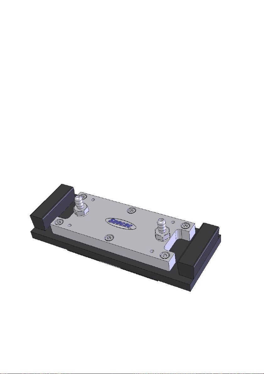
Fig 1. Gateway™ ATR Flow Through Top Plate

Gateway™ ATR Flow Through Top Plate
5
2. Safety Considerations
With use of any spectroscopic accessory that involves the study of a
wide range of chemical samples, the associated risk in handling may
mostly be attributed to the specific sample type to be handled itself. As
far as it possible you should follow a procedure for safe handling and
containment of the type of sample to be used.
With respect to safety of use specifically to the Gateway™ ATR
Accessory, this uses different crystal materials for the ATR crystal
Trough, Flat and Flow Through Top Plate assemblies where a sample
is bought into contact for analytical spectroscopic study. As standard,
Zinc Selenide (ZnSe), germanium (Ge) and Silicon (Si) are the three
crystal materials of choice that can be used.
Caution: Out of these three different crystal types, ZnSe is
the most potentially hazardous material with respect to
toxicity risk in use and handling.
Both Ge and Si crystal materials can be considered relatively safe to
use, although Ge may be harmful to the body if it is ingested in
significant quantity. The general rule when working with any crystal
material (and sample) is to always wear gloves and safety gear (e.g.
safety spectacles) when handling to obviate the risk of contact with the
skin.
Provided with each ATR crystal version of top plate assembly is a
window material safety data sheet for the crystal material itself that can
be consulted for safe handling. A copy of each of these datasheets can
also be found in the Gateway™ ATR instruction manual (2I-11165-4) in
the Notes on Cleaning Section found on pages 42, 43 and 44.

User Manual
6
3. Unpacking and Checklist
The Gateway™ ATR Flow Through Top Plate is supplied packed in a
black plastic carry case. The carry case contains the following:
•Flow Through ATR Top Plate
with Zinc Selenide crystal
(or as specified from
germanium and silicon options)
•ATR spectrum of the crystal as fitted to the Top Plate assembly to
show its background throughput.
•Clear silicone tubing for sample flow connection, 1/4” OD, 1/8” ID.
•Combination (open ended and ring) spanner 3/8” A/F.
•Allen Key (2.5mm A/F)
Remove the Gateway™ ATR Flow Through Top Plate from the
portable carry case and unwrap it from the protective polythene cover.

Gateway™ ATR Flow Through Top Plate
7
4. Alignment of the Gateway™ ATR Flow
Through Top Plate
The Gateway™ ATR Flow Through Top Plate is to be installed onto
the optical unit (GS11170) of the Gateway™ ATR Accessory for
operation in the study of flowing or static liquids at room temperature
conditions. The Flow Through Top Plate should be optimised for its
energy light throughput from a particular alignment of the mirrors on
the optical unit when installed for use.
If the Gateway™ ATR Accessory (as the Kit GS11165) is available for
use please follow the instruction manual supplied (2I-11165-4) for the
alignment procedure to optimize the liqht energy throughput of the ATR
system on your particular spectrometer using either the Trough Top
Plate (GS11166) or Flat Top Plate (GS11133) assembly as supplied.
The input and output mirror settings for their rotation and tilt angles will
be established on the optical unit (GS11170) from the alignment
procedure using either of these two Top Plates.
When subsequently placing the Flow Through Top Plate onto the
optical unit as a replacement for either the Trough (GS11166) or Flat
(GS11133) Top Plate assembly, a signal throughput will be registered,
but it is possible the mirrors in the optical unit may require slight re-
adjustment for an optimum throughput to be established in use of this
alternative Flow Through Top Plate. Therefore, follow the alignment
procedure with the Flow Through Top Plate in position to obtain the
best throughput energy signal for the spectrometers system.
Note: If just the Gateway™ optical unit (GS11170) and a Flow
Through Top Plate are available to use, unless the optical unit
has been pre-aligned to register some energy throughput with a
Top Plate in position, then it may be difficult to gain an optimum
alignment using the FTIR spectrometer systems energy source
and detection system. A rough pre-alignment is to be
established with the optical unit and Flow Through Top Plate in
position using a visible light source such as the Laser Alignment
Accessory (P/N GS24500).

User Manual
8
Fitting the Gateway™ ATR Flow Through Top Plate
The Gateway™ ATR Flow Through Top Plate fits onto the top of the
Gateway optical unit via alignment of the round hole (1) and slot hole
(2) on the underside of the Top Plate over the two fixing location pins
(3) on the optical unit. (See Fig 2 and Fig 3.)
Fig 2. Round and Slot Location Holes on Underside of
Gateway™ ATR Flow Through Top Plate
The Gateway™ ATR Flow Through Top Plate is fitted and positioned
the correct way around on the optical unit when the round hole (1) is
placed over the right side location pin (3R) and the slot hole (2) is
placed over the left side location pin (3L) as viewed from the front of
the optical unit. The main body plate (4) of the Top Plate should be
sitting flush and even all the way around its edge onto the top surface
of the optical unit when properly located.
Note: To maintain a correct optical alignment for consistency of optical
throughput energy of the Gateway™ ATR Flow Through Top
Plate, it should always be placed onto the optical unit the same
way around after removal for cleaning or crystal replacement
etc, with the round (1) and slot (2) holes fitting over their correct
and respective fixing location pins (3R) and (3L).
2
1
4

Gateway™ ATR Flow Through Top Plate
9
Fig 3. Fitting of Gateway™ ATR Flow Through Top Plate to the
Gateway™ Optical Unit
1
2
4
3L
3R
R
User Manual
10
5. Introducing the Liquid Sample
When the Gateway™ ATR Flow Through Top Plate has been correctly
installed onto the optical unit and aligned, then operation for collection
of a background spectrum and then a sample spectrum can begin.
(Please see Spectral Collection Using the Gateway™ ATR Accessory
from the instruction manual 2I-11165-4).
When using the Gateway™ ATR Flow Through Top Plate for liquid
sampling it is essential that the tubing connections are well secured to
the sample flow inlet and outlet ports (5) of the Top Plate assembly.
Important: The tubing connected to the ports (5) on the Top Plate
should be tested initially for liquid flow away from
installation on to the optical unit. This avoids any
accidental spillage of fluid onto the optical unit should the
flow tubes not happen to be well secured. The 3/8”
spanner supplied can be used to tighten the flow port
fittings (5) if any leaks occur at these positions.
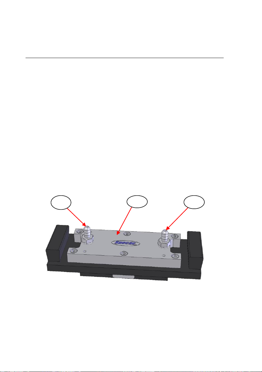
Fig 4. Liquid Connection Ports on Gateway™ ATR
Flow Through Top Plate
The clear silicone flow tubing supplied with the Gateway™ ATR Flow
Through Top Plate is connected to the flow ports (5) on the top section
5
6
5

Gateway™ ATR Flow Through Top Plate
11
plate (6). (See Fig 4). It does not matter which of the flow ports (5) is
the inlet or outlet connection for flow. The clear silicone tubing
supplied has dimensions of 1/4" O.D. and 1/8” I.D. and is pushed over
the barbed hose type connectors on the flow ports (5). Tie wraps can
be placed around the tubing at the flow port connections to prevent the
tubing from separating under a liquid sample flow.
Connect the other ends of the clear silicone tubing that has been
attached to the Flow Through Top Plate to a liquid sample supply and
follow the instructions for operation of a liquid sample pumping system
if this is being used to circulate the sample flow. The liquid sample
passes through the Flow Through Top Plate across the top surface of
the ATR crystal (7) contained within, for 6 ATR reflection measurement
events. (See Fig 5. for a cross section cutaway view of the Flow
Through Top Plate). There is an Isolast gasket (8) that seals between
the ATR crystal (7) top surface and the underside of the top section
plate (6) that creates the cavity for sample flow with a volume of 550
microlitres.
Fig 5. Cross Section Cutaway View Showing Internal Features of
the Gateway™ ATR Flow Through Top Plate
Note: When the liquid is flowing, the recommended normal pressure
usage is 60 psi maximum. A liquid can be measured in a static
mode if the flow system is switched off whilst the liquid is
contained within the Flow Through Top Plate cavity.
5
6
5
2
4
7
10
1
8
11

User Manual
12
6. ATR Crystal Removal and Replacement
The design of the Gateway™ ATR Flow Through Top Plate allows for
the ATR crystal (7) to be removable for easier cleaning or if damage
occurs and the crystal needs to be replaced.
Crystal Removal from the Flow Through Top Plate
If it is necessary to remove the crystal (7) for thorough cleaning of the
Top Plate assembly of parts or to replace any damaged parts etc, the
following procedure should be adopted.
Note:It is normally easier to work on the Top Plate assembly having
disconnected the silicone flow tubing from the inlet and outlet
sample flow ports (5).
Important: For safety precautions wear gloves when carrying out
the following procedure.
1) Lay the Top Plate assembly on to a clean workspace area and
proceed to remove the four M3 x 16mm cap head screws (9) from
the black, anodized lower clamp plate (10) on the underside of the
Top Plate assembly using the 2.5mm A/F Allen key supplied.
Turn the screws (9) anticlockwise to remove. (See Fig 6.)
Fig 6. Underside of Flow Through Top Plate Assembly
9
9
10

Gateway™ ATR Flow Through Top Plate
13
2) Between the underside of the clamp plate (10) and the ATR crystal
(7) there is a protective lead pad (11). Carefully remove the clamp
plate (10) away to gain access to the lead pad (11). (See Fig 7.) The
lead pad (11) may be stuck close to the underside of the crystal (7)
and so it needs to be removed very carefully away from the crystal.
Note: The lead pad (11) will be needed in any re-assembly after
cleaning of parts or if replacing with a new crystal (7).
Fig 7. Lead Pad on Underside of ATR Crystal
3) If the lead pad (11) has adhered to the crystal (7), then it may be
easier to remove it carefully away from the crystal when the crystal
(7) itself has been removed from its centralised position in its
recess of the main body plate (4). Therefore, support the crystal (7)
and the lead pad (11), with one hand and turn over the Top Plate
assembly so that the crystal (7) can fall out to drop into the palm of
your hand. If the crystal (7) is also stuck in the main body plate (4)
because of good sealing to the Isolast gasket (8) between the top
(sampling) surface of the crystal (7) and the top section plate (6),
then put a soft pad or tissue on the work bench area and lay the Top
Plate assembly onto it the same way up as it would be used when
fitted to the optical unit. Block one of the sample flow ports (5) and
connect the other port (5) to a clean, dry compressed air line and
allow a little pressure into the system. This should dislodge the
crystal (7) from the body plate (4) to fall onto the soft pad or tissue.
7
4
11

User Manual
14
When the crystal (7) and the lead pad (11) have been removed, it may
now be easier to separate the lead pad (11) from the crystal. If the
crystals (7) top sampling surface looks OK and can be cleaned
carefully, then it may not be necessary to remove the lead pad (11)
away for further cleaning prior to re-assembly and use. However, if the
lead pad (11) is to be removed, it may be necessary to immerse the
whole crystal (7) and lead pad (11) assembly in a beaker of water or
methanol solvent and apply a gentle “sonication cleaning”of the items.
The action of the sonic agitation of the solvent may help to loosen the
lead pad (11) away from the crystal such that when the items are
removed from the solvent they can be easily and safely separated
without any damage to the lead pad (11) or crystal (7) parts.
Clean the ATR crystal (7) by following the Notes on Cleaning
instructions on page 17.
Changing the Isolast Gasket Seal
When the ATR crystal (7) has been removed from the Top Plate
assembly, access can be gained to the Isolast gasket seal (8) for
cleaning or replacement with new if necessary. (See Fig 8.)
Fig 8. Isolast Gasket Seal in the Gateway™ ATR
Flow Through Top Plate
8
6
4

Gateway™ ATR Flow Through Top Plate
15
The Isolast gasket seal (8) is supplied already pre-cut to fit and is
purchased against P/N GS11150. Should the Isolast gasket (8) be
worn or damaged after inspection then replace with a new example. If
changing for a new gasket (8), ensure that all parts of the old gasket
are removed from the surface of the stainless steel top section plate
(6) to provide a good surface for resealing. It does not matter which
surface side of the Isolast gasket (8) is placed into contact with either
the underside of the top section plate (6) or the top surface of the
crystal (7).
Replacing the Crystal in the Top Plate Assembly
1) Having cleaned all of the parts sufficiently and whether installing a
new crystal (7) and/or new Isolast gasket (8), re-assemble the
Gateway™ ATR Flow Through Top Plate first by aligning correctly
and centrally the Isolast gasket seal (8) into the underside channel
recess of the main body plate (4). (See as for Fig 8.)
Important: Ensure that the sample port introduction holes (5) through
the top section plate (6) are not blocked or covered by an
incorrect positioning of the gasket (8).
2) Insert the ATR crystal (7) into the recess channel of the main body
plate (4) with the longer top surface of the crystal pressing against
the installed Isolast gasket (8) and the angled faces of the crystal (7)
pointing upwards. Ensure that the ends of the crystal (7) line up with,
or are equidistant from, the alignment marks on either side of the
recess channel in the main body plate (4) so that the crystal (7) is
sitting flat in the recess and not resting on an inclined chamfer face.
Note: If the crystal (7) is not placed flat and centrally against the
Isolast gasket (8) it will break when being pressure sealed from
repositioning and screw tightening of the underside clamp plate
(10).
3) Place the lead pad (11) carefully and centrally on the underside
face of the crystal (7), making sure that it does not obscure the input
or output angled faces of the crystal. (See as for Fig 7.)

User Manual
16
4) Carefully replace the lower clamp plate (10) over the lead pad (11)
and crystal (7) and refit the four screws (9). Ensure that the lead
pad (11) and crystal (7) are not dislodged from their central
positioning. (See as for Fig 6.)
5) Exert a pressure at the middle of the lower clamp plate (10) with
your thumb and tighten the four screws (9) a little at a time, in a
rotational sequence, to apply the pressure to the lead pad (11),
crystal (7) and Isolast gasket (8) assembly. The objective is to bring
the lower clamp plate (10) into contact evenly and levelly to the main
body plate (4) for tightening of the components together to avoid any
sample fluid leakage in operation.
Important: Do not over-tighten! All of the ATR crystal (7) material
types, but particularly ZnSe, are brittle crystal materials
and uneven pressure or over-tightening may fracture the
crystal (7).
6) Stand the re-assembled Flow Through Top Plate on a tissue
covering a work surface and test for leaks. Do not put it onto the
optical unit until tested. Test with a suitable solvent or mixture of
solvents at 70 psi for 30 minutes. (Note that the recommended
normal usage pressure is 60 psi maximum.)
If leaks occur, wipe the Top Plate area with a soft, lint-free tissue and
tighten the four screws (9) in the lower clamp plate (10) by about one
sixth of a turn for each screw and re-test.
Possible Causes of Leaks
Assembly not tightened sufficiently.
Lower clamp plate (10) and top section plate (6) surfaces not
sufficiently cleaned.
Isolast gasket seal (8) not lying flat.
Isolast gasket seal (8) is old/worn and requires replacement.
ATR crystal (7) is defective (e.g. chipped, dirty, warped).
ATR crystal (7) not symmetrically located.

Gateway™ ATR Flow Through Top Plate
17
Cleaning the Gateway™ ATR Flow Through Top Plate Intact
The procedure for cleaning of the crystal (7) with its removal from the
Top Plate assembly needs possibly to be carried out only very
occasionally. To avoid the need for cleaning the crystal outside of the
Top Plate assembly it is important to flush out any sample remaining
within the sampling area cavity by cleaning through with a suitable
solvent before storage. Clean, distilled water, methanol or acetone are
all suitable solvents to flush through for cleaning. After flushing through
with a cleaning solvent, any last vestiges of solvent may be sucked out
of the cavity by applying a light vacuum line attached to one of the flow
port connections (5) leaving the other flow port (5) open to allow for a
flow of air through the Top Plate and to pass over the ATR crystal (7).
Test that the crystal (7) is suitably clean by taking a spectral
measurement before storage of the Top Plate assembly in a clean, dry
cabinet, for example the Specacabinet (P/N GS19100), at about 40-
50°C.
Notes On Cleaning
When cleaning a ZnSe, Ge or Si crystal (7) of the Gateway™ ATR
Flow Through Top Plate assembly in preparation for a new sample, it
is very important to take care to avoid damage to the crystal
materials. As also mentioned in the Safety Considerations (Section 2,
page 5), of the three crystal materials ZnSe is potentially the most
hazardous in terms of risk of toxicity if it comes into contact with the
skin.
Note: Always wear gloves to protect yourself and the
ATR crystal material.
A useful feature of the Gateway™ ATR Accessory is the capability for
removal of any of the ATR crystal top plate assemblies away from the
optical unit, such that any sample can be prepared remotely and
safely, if desired, onto the ATR crystal (7) surface and then the ATR
crystal top plate assembly can be bought for fitting onto the optical unit
whilst installed in the spectrometer. Similarly for cleaning, it may be

User Manual
18
useful to remove any Top Plate assembly from the optical unit and
carry it to a safe area for solvent cleaning and wiping with a tissue and
therefore minimise any risk of contamination being carried over to
other components of the Accessory whilst in situ.
Solvents such as water, methanol and acetone are suitable to use for
cleaning purposes. Sample solutions that fall within the pH range of
pH5 to pH9 are tolerated by the ZnSe crystal material. Stronger acids
and bases will damage ZnSe irreparably. This range is intended as a
guide only, please ensure your samples are compatible with your
crystal choice
When wiping away any solid or liquid sample residues, use very soft
lens tissues to avoid scratches being caused on the surface of the ATR
crystals, particularly if using ZnSe material as this crystal type is
not as resilient as germanium or silicon crystals. Scratches and
blemishes to the ATR crystal (7) surface will result in poor light
throughput for the ATR technique and an overall degradation in the
Accessory performance.
In common and general usage of the Gateway™ ATR Flow Through
Top Plate it may only be necessary to flush through with a solvent to
clean away at the top surface of any Gateway™ ATR crystal (7) within,
between samples. If possible, try to avoid any solvent or cleaning
solution materials from getting to the underside of the Top Plate
assembly. There is a risk that any dried solution components that have
been introduced to this underside of the Top Plate assembly could be
seen as an “impurity” against the ATR crystal in any “background”
spectrum to be collected, and so this contaminant would need to be
removed before any further sampling can continue. Removal of such a
contaminant may require complete removal of the ATR crystal (7) from
the Gateway™ Flow Through Top Plate assembly and employment of
a suitable cleaning regime.
Other manuals for Gateway ATR
2
Table of contents
Other Specac Industrial Equipment manuals


Popular Industrial Equipment manuals by other brands


Global Industrial
Global Industrial B237006 Assembly instructions

M-system
M-system M8DY1 instruction manual

SJE Rhombus
SJE Rhombus 312 Installation and operation manual

Fröling
Fröling T4e operating instructions

FRANKLINWH
FRANKLINWH aPbox Installation and operation manual

movomech
movomech EASYCRANE Original instructions


