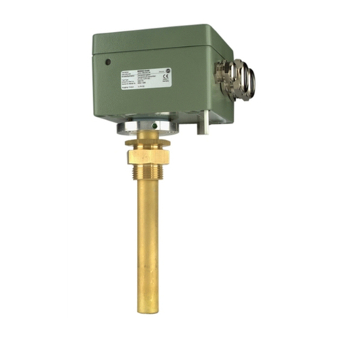
MR MESSKO combi well User manual

Operating instructions
MESSKO® combi well
8122419/01 EN
THE POWER BEHIND POWER.

© All rights reserved by Maschinenfabrik Reinhausen
Dissemination and reproduction of this document and use and disclosure of
its content are strictly prohibited unless expressly permitted.
Infringements will result in liability for compensation. All rights reserved in
the event of the granting of patents, utility models or designs.
The product may have been altered since this document was published.
We reserve the right to change the technical data, design and scope of
supply.
Generally the information provided and agreements made when processing
the individual quotations and orders are binding.
The original operating instructions were written in German.

8122419/01 EN . Table of contents 3
Table of contents
1 Introduction ................................................................... 5
1.1 Manufacturer ...........................................................................................5
1.2 Safekeeping .............................................................................................5
1.3 Notation conventions.............................................................................5
1.3.1 Hazard communication system.............................................................5
1.3.2 Information system.................................................................................6
1.3.3 Instruction system ..................................................................................7
1.3.4 Typographic conventions.......................................................................7
2 Security.......................................................................... 9
2.1 Appropriate use.......................................................................................9
2.2 Fundamental safety instructions.........................................................10
2.3 Personnel qualification .........................................................................12
2.4 Personal protective equipment ........................................................... 13
3 Product description.......................................................15
3.1 Function description and design .........................................................15
3.2 Nameplate ............................................................................................. 17
4 Packaging, transport and storage ................................ 18
4.1 Purpose ..................................................................................................18
4.2 Suitability, structure and production...................................................18
4.3 Markings.................................................................................................19
4.4 Transportation, receipt and handling of shipments ..........................19
4.5 Storage of shipments ...........................................................................21
5 Mounting...................................................................... 22
5.1 Electromagnetic compatibility .............................................................22
5.1.1 Wiring requirement of installation site ..............................................22
5.1.2 Wiring requirement of operating site .................................................23
5.2 Cable recommendation....................................................................... 24
5.3 Mounting and connecting the combi well ......................................... 24
6 Commissioning ............................................................ 33
6.1 Performing a dielectric test ..................................................................33
6.2 Performing comparison measurements.............................................33
Table of contents . 8122419/01 EN
4
7 Maintenance, inspection and care................................ 34
8 Disposal ....................................................................... 35
9 Technical data.............................................................. 36
9.1 Basic materials.......................................................................................36
9.2 Pt100 output..........................................................................................36
9.3 Current output (combi TT) ...................................................................36
9.4 Operating conditions and ambient conditions ..................................37
10 Drawings...................................................................... 38
10.1 10149547................................................................................................39
Glossary .......................................................................40

8122419/01 EN . Introduction 5
1 Introduction
This technical file contains detailed descriptions on the safe and proper in-
stallation, connection, commissioning and monitoring of the product.
This technical document is intended solely for specially trained and autho-
rized personnel.
1.1 Manufacturer
Maschinenfabrik Reinhausen GmbH
Falkensteinstrasse 8
93059 Regensburg
Germany
Tel.: +49 941 4090-0
E-mail: [email protected]
Internet: www.reinhausen.com
MR Reinhausen customer portal: https://portal.reinhausen.com
Further information on the product and copies of this technical file are avail-
able from this address if required.
1.2 Safekeeping
Keep this technical file and all supporting documents ready at hand and ac-
cessible for future use at all times.
1.3 Notation conventions
This section contains an overview of the symbols and textual emphasis used.
1.3.1 Hazard communication system
Warnings in this technical file are displayed as follows.

Introduction . 8122419/01 EN6
1.3.1.1 Warning relating to section
Warnings relating to sections refer to entire chapters or sections, sub-sec-
tions or several paragraphs within this technical document. Warnings relating
to sections have the following format:
WARNING
Type of danger!
Source of the danger and its consequences.
Action
Action
1.3.1.2 Embedded warning information
Embedded warnings refer to a particular part within a section. These warn-
ings apply to smaller units of information than the warnings relating to sec-
tions. Embedded warnings use the following format:
DANGER! Instruction for avoiding a dangerous situation.
1.3.1.3 Signal words
Depending on the product, the following signal words are used:
Signal word Meaning
DANGER Indicates a hazardous situation which, if not avoided, will result in
death or serious injury.
WARNING Indicates a hazardous situation which, if not avoided, could result in
death or serious injury.
CAUTION Indicates a hazardous situation which, if not avoided, could result in
minor or moderate injury.
NOTICE Indicates measures to be taken to prevent damage to property.
Table1: Signal words in warning notices
1.3.2 Information system
Information is designed to simplify and improve understanding of particular
procedures. In this technical file it is laid out as follows:

8122419/01 EN . Introduction 7
Important information.
1.3.3 Instruction system
This technical file contains single-step and multi-step instructions.
Single-step instructions
Instructions which consist of only a single process step are structured as fol-
lows:
Aim of action
Requirements (optional).
1. Step 1 of 1.
Result of step (optional).
Result of action (optional).
Multi-step instructions
Instructions which consist of several process steps are structured as follows:
Aim of action
Requirements (optional).
1. Step 1.
Result of step (optional).
2. Step 2.
Result of step (optional).
Result of action (optional).
1.3.4 Typographic conventions
Typographic convention Purpose Example
UPPERCASE Operating controls,
switches
ON/OFF
[Brackets] PC keyboard [Ctrl] + [Alt]
Bold Software operating controls Press Continue button
…>…>… Menu paths Parameter > Control param-
eter

Introduction . 8122419/01 EN8
Typographic convention Purpose Example
Italics System messages, error
messages, signals
Function monitoring alarm
triggered
[► Number of pages] Cross reference [► Page41].
Dotted underscore
.............................................
Glossary entry, abbrevia-
tions, definitions, etc.
Glossary entry
........................
Table2: Typographic conventions used in this technical file

8122419/01 EN . Security 9
2 Security
–Read this technical file through carefully to familiarize yourself with the
product.
–This technical file is a part of the product.
–Read and observe the safety instructions provided in this chapter in partic-
ular.
–Observe the warnings in this technical file to avoid function-related dan-
gers.
–The product is manufactured based on state-of-the-art technology. Never-
theless, danger to life and limb for the user or impairment of the product
and other material assets may arise in the event of improper use.
2.1 Appropriate use
The combi well is used for the remote transmission of a measured tempera-
ture value and is used in combination with a pointer thermometer or an eval-
uation instrument.
The product is designed solely for use in stationary large-scale systems.
If used as intended and in compliance with the requirements and conditions
specified in this technical file as well as the warning notices in this technical
file and attached to the product, then the product does not present any dan-
ger to people, property or the environment. This applies throughout the ser-
vice life of the product, from delivery, installation and operation to removal
and disposal.
The following is considered intended use:
–Only use the product for transformers.
–Operate the product in accordance with this technical documentation, the
agreed-upon delivery conditions and the technical data.
–Ensure that all necessary work is performed by qualified personnel only.
–Use the equipment and special tools supplied solely for the intended pur-
pose and in accordance with the specifications of this technical file.

Security . 8122419/01 EN10
2.2 Fundamental safety instructions
To prevent accidents, malfunctions and damage as well as unacceptable ad-
verse effects on the environment, those responsible for transport, installa-
tion, operation, maintenance and disposal of the product or parts of the
product must ensure the following:
Personal protective equipment
Loosely worn or unsuitable clothing increases the danger of becoming
trapped or caught up in rotating parts and the danger of getting caught on
protruding parts. This results in danger to life and limb.
–All necessary devices and personal protective equipment required for the
specific task, such as a hard hat, safety footwear, etc. must be worn. Ob-
serve the "Personal protective equipment" [►Section 2.4, Page 13] sec-
tion.
–Never wear damaged personal protective equipment.
–Never wear rings, necklaces or other jewelry.
–If you have long hair, wear a hairnet.
Work area
Untidy and poorly lit work areas can lead to accidents.
–Keep the work area clean and tidy.
–Make sure that the work area is well lit.
–Observe the applicable laws for accident prevention in the relevant coun-
try.
Explosion protection
Highly flammable or explosive gases, vapors and dusts can cause serious ex-
plosions and fire.
–Do not install or operate the product in areas where a risk of explosion is
present.

8122419/01 EN . Security 11
Safety markings
Warning signs and safety information plates are safety markings on the prod-
uct. They are an important aspect of the safety concept. Safety markings are
depicted and described in the chapter "Product description".
–Observe all safety markings on the product.
–Make sure all safety markings on the product remain intact and legible.
–Replace safety markings that are damaged or missing.
Ambient conditions
To ensure reliable and safe operation, the product must only be operated un-
der the ambient conditions specified in the technical data.
–Observe the specified operating conditions and requirements for the in-
stallation location.
Modifications and conversions
Unauthorized or inappropriate changes to the product may lead to personal
injury, material damage and operational faults.
–Only modify the product after consultation with Maschinenfabrik Rein-
hausen GmbH.
Spare parts
Spare parts not approved by Maschinenfabrik Reinhausen GmbH may lead to
physical injury, damage to the product and malfunctions.
–Only use spare parts that have been approved by Maschinenfabrik Rein-
hausen GmbH.
–Contact Maschinenfabrik Reinhausen GmbH.
Working during operation
You must only operate the product when it is in a sound operational condi-
tion. Otherwise it poses a danger to life and limb.
–Regularly check the operational reliability of safety equipment.
–Perform the inspection tasks described in this technical document regu-
larly.

Security . 8122419/01 EN12
2.3 Personnel qualification
The person responsible for assembly, commissioning, operation and inspec-
tion must ensure that personnel are sufficiently qualified.
Electrically skilled person
The electrically skilled person has a technical qualification and therefore has
the required knowledge and experience, and is also conversant with the ap-
plicable standards and regulations. The electrically skilled person is also profi-
cient in the following:
–Can identify potential dangers independently and is able to avoid them.
–Is able to perform work on electrical systems.
–Is specially trained for the working environment in which (s)he works.
–Must satisfy the requirements of the applicable statutory regulations for
accident prevention.
Electrically trained persons
An electrically trained person receives instruction and guidance from an elec-
trically skilled person in relation to the tasks undertaken and the potential
dangers in the event of inappropriate handling as well as the protective de-
vices and safety measures. The electrically trained person works exclusively
under the guidance and supervision of an electrically skilled person.
Operator
The operator uses and operates the product in line with this technical file.
The operating company provides the operator with instruction and training
on the specific tasks and the associated dangers arising from improper han-
dling.
Technical Service
We strongly recommend having repairs and retrofitting carried out by our
Technical Service department. This ensures that all work is performed cor-
rectly. If repair work is not carried out by our Technical Service department,
please ensure that the personnel who carry out the repairs are trained and
authorized to do so by Maschinenfabrik Reinhausen GmbH.

8122419/01 EN . Security 13
Maschinenfabrik Reinhausen GmbH
Technical Service
P.O. Box 12 03 60
93025 Regensburg
Germany
Phone: +49 941 4090-0
E-mail: [email protected]
Internet: www.reinhausen.com
2.4 Personal protective equipment
Personal protective equipment must be worn during work to minimize risks
to health.
–Always wear the personal protective equipment required for the job at
hand.
–Never wear damaged personal protective equipment.
–Observe information about personal protective equipment provided in the
work area.
Protective clothing Close-fitting work clothing with a low tearing strength,
with tight sleeves and with no protruding parts. It mainly
serves to protect the wearer against being caught by mov-
ing machine parts.
Safety shoes To protect against falling heavy objects and slipping on
slippery surfaces.
Safety glasses To protect the eyes from flying parts and splashing liquids.
Visor To protect the face from flying parts and splashing liquids
or other dangerous substances.

Security . 8122419/01 EN14
Hard hat To protect against falling and flying parts and materials.
Hearing protection To protect against hearing damage.
Protective gloves To protect against mechanical, thermal and electrical haz-
ards.
Table3: Personal protective equipment

8122419/01 EN . Product description 15
3 Product description
This chapter contains an overview of the design and function of the product.
3.1 Function description and design
The combi well is a mounting well with additional measurement resistor for
oil pointer thermometers and is used for the remote transmission of mea-
sured temperature values. Depending on the device type, the electrical tem-
perature measurement can be transmitted remotely as follows:
–Combi well (standard): Connection via the integrated Pt100 measurement
resistor
–Combi TT: Connection via an analog 4...20mA output

Product description . 8122419/01 EN16
The terminal connections for the evaluation devices as well as a cable gland
for the immersion pipe for the temperature sensor of the pointer thermome-
ter are located in the connection head. The combi well can be combined with
various pointer thermometers and evaluation instruments. Read the operat-
ing instructions for these.
Figure1: Combi well
1 Connection head 2 Cable gland
3 Double screw connection G1 4 Immersion pipe
5 Integrated Pt100 resistor 6 Temperature sensor
7 Pressure equalization element

8122419/01 EN . Product description 17
3.2 Nameplate
The nameplate is on the rear of the device.
Figure2: Nameplate

Packaging, transport and storage . 8122419/01 EN18
4 Packaging, transport and storage
4.1 Purpose
The packaging is designed to protect the packaged product during transport,
loading, unloading and during periods of storage in such a way that no detri-
mental changes occur. The packaging must protect the goods against per-
mitted transport stresses such as vibration, knocks and moisture (rain, snow,
condensation).
The packaging also prevents the packaged goods from moving impermissibly
within the packaging.
4.2 Suitability, structure and production
The goods are packaged in a sturdy cardboard box or solid wooden crate.
These ensure that the shipment is secure when in the intended transporta-
tion position and that none of its parts touch the loading surface of the
means of transport or touch the ground after unloading.
Inlays inside the box or crate stabilize the goods, preventing impermissible
changes of position and protecting them from vibration.

8122419/01 EN . Packaging, transport and storage 19
4.3 Markings
The packaging bears a signature with instructions for safe transport and cor-
rect storage. The following symbols apply to the shipment of non-hazardous
goods. Adherence to these symbols is mandatory.
Protect against
moisture
Top Fragile Attach lifting
gear here
Center of mass
Table4: Shipping pictograms
4.4 Transportation, receipt and handling of shipments
In addition to vibrations, jolts must also be expected during transportation.
To prevent possible damage, avoid dropping, tipping, knocking over and col-
liding with the product.
If the packaging tips over or falls, damage is to be expected regardless of the
weight.
Every delivered shipment must be checked for the following by the recipient
before acceptance (acknowledgment of receipt):
–Completeness based on the delivery slip
–External damage of any type.
The checks must take place after unloading when the cartons or transport
container can be accessed from all sides.

Packaging, transport and storage . 8122419/01 EN20
Visible damage
If external transport damage is found upon receipt of the shipment, proceed
as follows:
–Immediately record the transport damage found in the shipping docu-
ments and have this countersigned by the carrier.
–In the event of severe damage, total loss or high damage costs, immedi-
ately notify the sales department at Maschinenfabrik Reinhausen GmbH
and the relevant insurance company.
–After identifying damage, do not modify the condition of the shipment fur-
ther and retain the packaging material until an inspection decision has
been made by the transport company or the insurance company.
–Record the details of the damage immediately on site together with the
carrier involved. This is essential for any claim for damages.
–If possible, photograph damage to packaging and packaged goods. This
also applies to signs of corrosion on the packaged goods due to moisture
inside the packaging (rain, snow, condensation).
–Be absolutely sure to also check the sealed packaging.
Hidden damage
When damage is not determined until unpacking after receipt of the ship-
ment (hidden damage), proceed as follows:
–Make the party responsible for the damage liable as soon as possible by
telephone and in writing, and prepare a damage report.
–Observe the time periods applicable to such actions in the respective
country. Inquire about these in good time.
With hidden damage, it is very hard to make the transportation company (or
other responsible party) liable. Any insurance claims for such damage can
only be successful if relevant provisions are expressly included in the insur-
ance terms and conditions.
Table of contents
Other MR Industrial Equipment manuals

MR
MR ECOTAP VPD 3 30D-24 User manual

MR
MR VACUTAP VMS User manual

MR
MR MESSKO MTRAB User manual

MR
MR TAPCON User manual

MR
MR TAPCON 230 basic User manual

MR
MR VACUTAP VV-Ex Series User manual

MR
MR VACUTAP VR User manual

MR
MR VACUTAP VR Installation and operation manual

MR
MR VACUTAP VV Installation and operation manual

MR
MR VACUTAP VR User manual

MR
MR VACUTAP User manual

MR
MR MESSKO MPREC User manual

MR
MR VACUTAP VR Series Installation and operation manual

MR
MR TAPMOTION ED Series User manual

MR
MR VACUTAP RMV-II User manual

MR
MR MESSKO ZT-F2.1 User manual

MR
MR ComTroll 115C User manual

MR
MR CEDASPE VP Series User manual

MR
MR VACUTAP VR I HD-Ex Installation and operation manual

MR
MR ECOTAP VPD I User manual