Specac GS15051 User manual

Low Tonnage Gauge Kits for
Atlas™ Manual Hydraulic Presses
User Manual
2I-15051-8


Low Tonnage Gauge Kits for
Atlas™ Manual Hydraulic Presses
User Manual
2I-15051-8

User Manual
2
Low Tonnage Gauge Kits for Atlas™ Manual
Hydraulic Presses P/N’s GS15051/52/55
CONTENTS –USER MANUAL
1. INTRODUCTION .................................................................................3
2. UNPACKING AND CHECKLIST .............................................................5
3. INSTALLATION OF THE LOW TONNAGE GAUGE KIT TO THE ATLAS™
MANUAL HYDRAULIC PRESS..............................................................6
PROCEDURE FOR FITTING.................................................................6
4. OPERATION OF THE ATLAS™MANUAL HYDRAULIC PRESS WITH A
LOW TONNAGE GAUGE FITTED........................................................10
SAFETY WARNINGS WHEN OPERATING THE PRESS ..........................10
BLEEDING AIR FROM THE LOW TONNAGE GAUGE KIT .......................10
SWITCHING ON AND OFF THE LOW TONNAGE GAUGE.......................13
5. LEGEND -BUBBLE NUMBER PART IDENTIFICATION ...........................14
6. SPARE PARTS FOR THE LOW TONNAGE GAUGE KITS........................14
© April 2016 Specac Ltd. All rights reserved.
Brilliant Spectroscopy is a trademark of Specac Ltd.
Other product names mentioned herein may be trademarks
of their respective owners.

Low Tonnage Gauge Kits for Atlas™ Manual Hydraulic Presses
3
1. Introduction
Thank you for buying a Specac product.
The Low Tonnage Gauge Kits enable a standard Atlas™ 15T or 25T
Manual Hydraulic Press (P/N GS15011 and P/N GS25011
respectively) to be used more accurately for the reading of a low
tonnage load that has been applied during a pressing. The low
tonnage gauge conversion kits for a 0 to 1 tons range (P/N GS15051),
0 to 2 tons range (P/N GS15052) and 0 to 5 tons range (P/N GS15055)
provide an ADDITIONAL low tonnage load gauge to be used along
with the standard 15 or 25 ton load gauge fitted on the press.
The appropriate low tonnage gauge kit is fitted by the user to allow
both gauges to be connected to the press and used in-line to register
an applied tonnage load. The lower tonnage gauge that has been fitted
in this way to a press can be independently switched off from the
pressure system, but any pressure of oil in the system will always be
registered as an appropriate applied tonnage load at the 15 or 25 ton
gauge fitted.
The lower tonnage load gauge has finer divisions for reading of an
applied load, so, for example, if it is important to know that you are
applying say 4.1 tons as opposed to possibly 4.5 tons, then the low
tonnage gauge kit for a 0 to 5 ton load range would be required for
fitting to the press.
Beware! When a low tonnage gauge kit option is fitted to a press, the
press itself can only be operated up to the maximum load
allowable when the particular low tonnage gauge is switched
on line for reading the load. (e.g. 2 tons maximum load for the
0 to 2 tons load gauge kit P/N GS15052).
As an operating safety precaution, to prevent accidental over-
pressurisation of a lower tonnage gauge when fitted (if it has not been
switched off-line when higher tonnage loads are to be applied),
Specac recommend that the pressure relief valve assembly situated
underneath the standard load gauge of the press is adjusted to vent off

User Manual
4
at the maximum tonnage load capability of the low tonnage gauge
fitted. Higher tonnage loads than the low tonnage gauge maximum can
still be obtained on the 15T or 25T press if they are to be applied, but
then the pressure relief valve assembly will have to be readjusted to
allow for a higher tonnage load to be hand pumped and contained on
the system and therefore the low tonnage load gauge control valve
MUST also be turned off.
As an example for use of the 0 to 5 ton low tonnage gauge kit P/N
GS15055 when fitted to an Atlas™ 15T Manual Hydraulic Press P/N
GS15011 (which can be operated to apply up to a 15 ton maximum
load), set the pressure relief valve accordingly such that a maximum
load for 5 tons can be hand pumped on the press. This maximum load
is indicated on both the standard 0 to 15 ton load gauge and 0 to 5 ton
low tonnage load gauges that have been fitted. Any further pulls on the
pump handle of the press results in an excess pressure being vented
off at the pressure relief valve. In this way the pressure relief valve acts
as a safety device to not only prevent overloading of and damage to
the low tonnage gauge mechanism, but also to any sample or die
assembly in the pressing area of the press itself.
If a tonnage load higher than 5 tons is needed for application, switch
off the low tonnage load gauge at its control valve and re-adjust the
pressure relief valve assembly for a higher tonnage load to be applied
and contained.
Therefore, use of an Atlas™ 15T Manual Hydraulic Press allows for
any tonnage load up to 15 tons to be applied to a sample or an
evacuable pellet die in the pressing area. However, if a finer reading of
the load applied up to a maximum of 5 tons is required, then the low
tonnage gauge kit P/N GS15055 can be fitted to the press and the
additional low tonnage gauge provided is switched on-line.
Low Tonnage Gauge Kits for Atlas™ Manual Hydraulic Presses
5
2. Unpacking and Checklist
On receipt of your Low Tonnage Gauge Kit please check that the
following parts have been supplied.
● 1 Manifold body (square tube) assembly
with 0 to 1, 0 to 2, or 0 to 5 tons
load gauge fitted.
● 1 Fixing bolt. (Fixing bolt with two Dowty
seals is already in position at base of
manifold body with a little red cap seal).
● 1 Open ended spanner (18mm A/F and 19mm A/F).
● 1 Spare (Dowty) seal for gauge connection part of press.
● 1 Instruction manual.
Carefully remove the parts from packaging and prepare the parts for
fitting to the Atlas™ Manual Hydraulic Press.

User Manual
6
3. Installation of the Low Tonnage Gauge Kit to
the Atlas™ Manual Hydraulic Press
The Low Tonnage Gauge Conversion Kit is an additional assembly
of parts that a user can fit to an Atlas™ 15T or 25T Manual Hydraulic
Press to provide a facility of a finer reading for any tonnage load being
applied, up to the maximum load capability of the particular low
tonnage gauge fitted.
Note: Specac recommend to test that the press you are using and
would wish to adapt with a low tonnage gauge kit is functioning
correctly to apply a tonnage load, before having to partially
dismantle some of the parts from the pump block assembly of
the press and rebuild it from the parts supplied with the low
tonnage gauge kit. If a subsequent fitting of new parts introduces
a problem of non-functionality (e.g. an airlock in the oil), you may
be able to pinpoint more readily what is needed to correct and to
get the new system operational.
Procedure for Fitting
To help in the explanation of the procedure for fitting a low tonnage
gauge kit to an Atlas™ manual hydraulic press, relevant parts in the
following diagrams (Figs.) have been identified with a “bubble” part
number that corresponds directly to the same part number as indicated
in the Atlas™ Manual Hydraulic Press’s own user instruction manual.
New parts from the low tonnage gauge kits have been “bubble” part
numbered accordingly for consistency with the press numbering
system.
The original load gauge (31) (15 or 25 tons) of the press is removed
from the pump block assembly of the press and fitted to the manifold
body (74) of the low tonnage gauge kit that already has the low
tonnage gauge (75) option (1 ton, 2 tons or 5 tons range) fitted. The
whole assembly of parts is then fitted onto the press at the pump block
assembly from where the 15 or 25 tons load gauge has been removed.

Low Tonnage Gauge Kits for Atlas™ Manual Hydraulic Presses
7
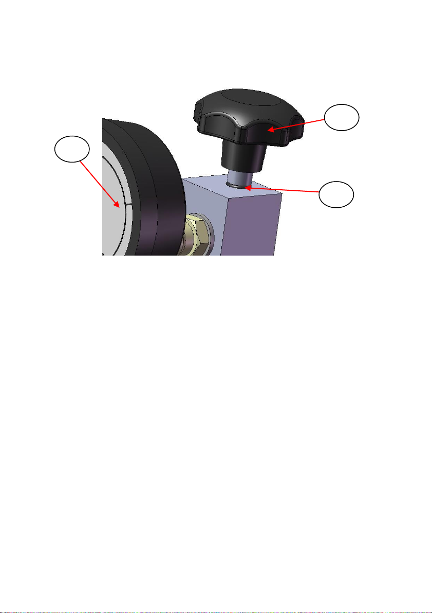
Loosen the gauge connector (39) fitting to the load gauge (31) by
unscrewing the top nut (N1) connection (see Fig 1.) using the 19mm
A/F end of the spanner supplied.
Note: The connection (39) nut at (N1) must be turned clockwise,
using the 19mm A/F spanner and holding the gauge (31) with
your other hand to separate the threaded parts.
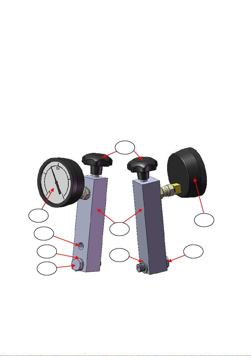
Fig 1. Load Gauge Connector Part of Press
Carefully remove the load gauge (31) and put it by for safe keeping.
(See Fig 2.)
Fig 2. Removal of 15/25 Ton Load Gauge from Manual Press
31
39
48
N1
N2
39
30
User Manual
8
The gauge connector (39) is then removed from the pump block
assembly by unscrewing the lower nut (N2) connection by the “Dowty”
seal (48). (See Fig 1. and Fig 2.) (Unscrew - turn (N2) anticlockwise.)
Transfer the gauge connector (39) and Dowty seal (48) parts for fitting
to the bore opening (76) of the manifold body (74) by tightening of the
lower nut connection (N2). (See Fig 1. and Fig 3.) If the removed
Dowty seal (48) from the press is not suitable for re-use, then use the
spare seal provided with the low tonnage gauge kit.
Note: The bore opening (76) on the manifold body (74) will be plugged
with a transport screw to prevent dust from entering. Remove
this screw before fitting of the gauge connector (39) and Dowty
seal (48) parts.
Fig 3. Front and Rear View of Low Tonnage Gauge Kit
Remove the dust cover cap from the fixing bolt (77) and Dowty seal
(78) parts at the base of the manifold assembly (74). (See Fig 3.)
75
76
78
79
74
78
75
77
77
Low Tonnage Gauge Kits for Atlas™ Manual Hydraulic Presses
9
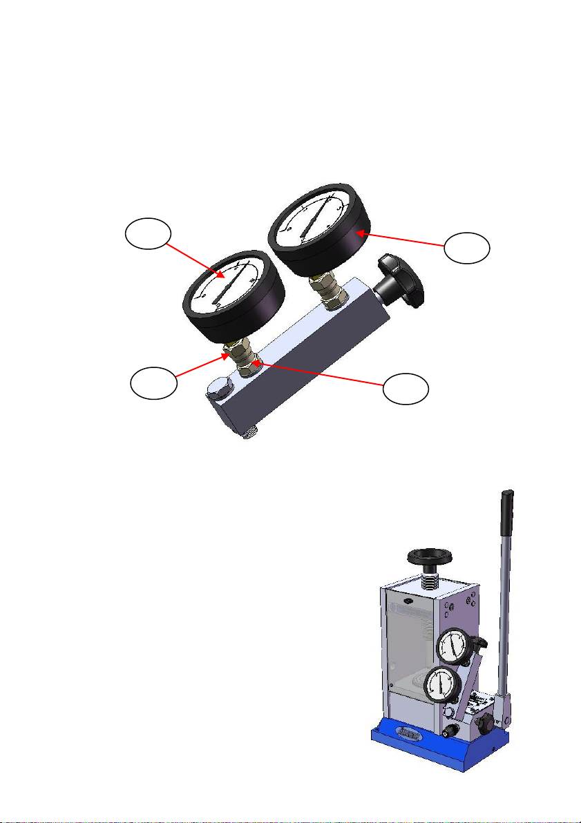
When the gauge connector (39) has been fitted to the manifold tube
(74), fit the 15 or 25 ton load gauge (31) to the gauge connector by
tightening of the top nut (N1) connection. (See Fig 4.) Tighten together
by turning (N1) anticlockwise and holding the load gauge (31).
Fig 4. Both Gauges Fitted to the Manifold Block
Proceed to fit the complete manifold tube
assembly with the two gauges via the fixing
bolt (77) and Dowty seal (78) into position
on the pump block assembly of the press,
from where the original gauge (31) and
gauge connector (39) have been removed.
Tighten the fixing bolt (77) using the 19mm
A/F end of the spanner supplied. The
completed assembly of parts for a low
tonnage gauge kit as fitted to an Atlas™
manual hydraulic press is shown as Fig 5.
Fig 5. Complete Kit Assembly Fitted
to a Manual Press
39
75
31
N1

User Manual
10
4. Operation of the Atlas™ Manual Hydraulic
Press with a Low Tonnage Gauge Fitted
Safety Warnings When Operating the Press
Important: As mentioned in the Introduction, it is extremely important
that the Atlas™ manual hydraulic press is restricted to the
maximum load limit of any low tonnage gauge fitted
before use. Instructions how to set the load limit using the
pressure relief valve assembly are found in the user
instruction manual for the Atlas™ manual hydraulic press.
This setting will prevent any over-pressurisation to the low
tonnage load gauge (75) that would damage the gauge if
the open/close valve tap (79) for the low pressure gauge is
accidentally left open when higher tonnage loads are
wished to be pumped on the press.
Bleeding Air from the Low Tonnage Gauge Kit
Before the Atlas™ manual hydraulic press can be used to apply a
tonnage load with the fitting of a low tonnage gauge kit, any possibility
of air that might be trapped in the oil, preventing a pressure build up,
must be bled from the manifold body (77).
To bleed any trapped air from the oil, carry out the following procedure:
Place an “unyielding” sample/work (e.g. a cylindrical block of metal) to
press in the usual way, within the pressing area of the Atlas™ manual
hydraulic press. Ensure that the the metal block to press is loosely
clamped between the lead screw top bolster pressing face and the
lower bolster pressing piston face.
Ensure the open/close valve tap (79) on the manifold body (77) is
closed. Closing the valve tap (79) isolates the low tonnage gauge (75)
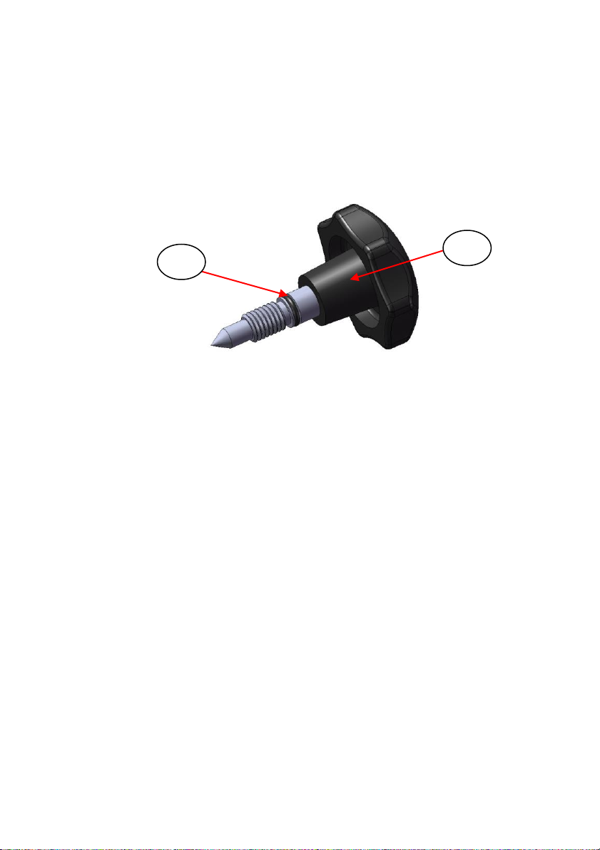
Low Tonnage Gauge Kits for Atlas™ Manual Hydraulic Presses
11
that has been fitted, to stop any oil pressure pumped on the system
from reaching it. The valve tap (79) is a tapered “needle” type fitting
and will be closed when the tap handle (79) is turned hand tight in a
clockwise direction. There is an O-ring (80) on the valve tap assembly
that makes an oil-tight seal when fully closed. (See Fig 6.)
Fig 6. Low Tonnage Gauge Open/Close Valve Tap Assembly
Close the pressure release handle (30) of the press by turning
clockwise (see Fig 2.) and begin to hand pump the press (slowly) in
the usual way. Oil will be pressurized and forced from the press
reservoir up and into the manifold body (77) to register at the higher
load tonnage gauge (31) fitted at the base of the manifold body (77)
and towards the shut off valve tap assembly (79). Pump to apply a
tonnage load of about 1 (one) ton (no more) against the metal block to
be registered at the higher tonnage load gauge (31) as fitted.
Now, very slowly open the valve tap (79) by anti-clockwise rotation of
the handle until the O-ring (80) is just beginning to emerge from the top
of the manifold body (77). (See Fig 7.) Any air that may be trapped in
the manifold body (77) will be forced out at the top past the opened
valve tap (79) and by the O-ring seal (80) from the oil pressure that has
been pumped on the system. When air and oil is observed at the valve
tap (79) by the O-ring (80), a slight decrease in the tonnage load that
has been applied at the higher tonnage load gauge (31) and a
registering of a low tonnage load at the low tonnage gauge (75) fitted
will also be observed.
80
79
User Manual
12
Fig 7. Opening of Valve Tap for Bleed of Air Procedure
Note: Be very careful when opening the valve tap (79). It is not
necessary to open it any further than when the O-ring appears
and any air bubbles emerge with release of some pressurised
oil. Applying a low tonnage reading of 1 ton to the metal block,
ensures there is sufficient oil pressure in the system to allow the
air to be bled off at this point of the manifold body (77) assembly.
It is also a safe load to apply if the LOWEST tonnage gauge of 0
to 1 tons range has been fitted to the manifold body (77) and
this gauge is switched on line to register an oil pressure from
the bleed of air procedure.
When the oil flows freely and no more air bubbles are observed,
tighten the valve tap (79) clockwise to close it fully again. The newly
fitted low tonnage gauge kit with twin gauges fitted to the press should
now have been successfully bled free of air.
Release the overall pressure in the system and hence load from the
metal block in the press by opening slowly and slightly (turn anti-
clockwise) the pressure release valve (30) on the press.
75
79
80
Open Valve Tap
Until O-ring Just
Shows

Low Tonnage Gauge Kits for Atlas™ Manual Hydraulic Presses
13
Now, still with the valve tap (79) closed, follow the procedure to adjust
the pressure relief valve assembly on the press to set a maximum
tonnage load achievable on the press that corresponds to the
maximum load capability of the low tonnage gauge (75) as fitted.
(1 ton, 2 tons or 5 tons range.) The procedure to adjust the pressure
relief valve is found in the user instruction manual for the Atlas™
manual hydraulic press.
Switching On and Off the Low Tonnage Gauge
To bring the low tonnage gauge “on line” for load reading, the valve tap
(79) on the manifold body (77) is opened. (79) is a needle type valve
(See Fig 6.) and the tap handle only needs a quarter to half turn
maximum anti-clockwise to open for the low tonnage gauge (75) to be
switched on to register a tonnage load.
Beware: If the valve tap (79) is opened too far from turning the handle
anti-clockwise for operation of the low tonnage gauge, there
is a risk that the O-ring (80) will not seal effectively and so oil
pressure in the system will be lost and there will be no
effective build-up of a tonnage load that can be applied to any
work/sample being held in the press.
The following table shows the situation relating to which gauge is
working when the pressure release valve (30) on the press and the
valve tap (79) on the manifold body (77) are either open and/or closed.
Valve
Status of Valve
Gauge Being Used
(30)
(79)
Open
Open
Neither
(30)
(79)
Closed
Open
(31)
(75)
(30)
(79)
Closed
Closed
(31)
(30)
(79)
Open
Closed
Neither

User Manual
14
5. Legend –Bubble Number Part Identification
(30) Pressure release handle (valve) on press.
(31) Original 15 or 25 ton load gauge on press.
(39) Load gauge connector fitting on press.
(48) Dowty seal for gauge connector fitting on press.
(74) Manifold body of low tonnage gauge kit.
(75) Low tonnage gauge (0 to 1, 0 to 2, or 0 to 5 ton range option).
(76) Bore opening on manifold body.
(77) Manifold body fixing bolt.
(78) Dowty seal (2 off) for manifold body fixing bolt.
(79) Open/close valve tap assembly for low tonnage gauge.
(80) O-ring seal on valve tap assembly for low tonnage gauge.
6. Spare Parts for the Low Tonnage Gauge Kits
P/N GS15051 0 to 1 ton Low Tonnage Gauge Kit.
P/N GS15052 0 to 2 ton Low Tonnage Gauge Kit.
P/N GS15055 0 to 5 ton Low Tonnage Gauge Kit.

Notes for Use of Low Tonnage Gauge Kit

Notes for Use of Low Tonnage Gauge Kit

Worldwide Distribution
France
Eurolabo - Paris.
Tel.01 42 08 01 28
Fax 01 42 08 13 65
email: contact@eurolabo.fr
Germany
L.O.T. - Oriel GmbH & Co,
KG - Darmstadt
Tel: 06151 88060
Fax: 06151 880689
email:info@LOT-Oriel.de
Website: www.LOT-Oriel.com/de
Japan
Systems Engineering Inc. -Tokyo
Tel: 03 3946 4993
Fax: 03 3946 4983
email:systems-eng@systems-eng.co.jp
Website: www.systems-eng.co.jp
Spain
Teknokroma S.Coop C. Ltda
Barcelona
Tel: 93 674 8800
Fax: 93 675 2405
email: comercial@teknokroma.es
Switzerland
Portmann InstrumentsAG
Biel-Benken
Tel: 061 726 6555
Fax: 061 726 6550
email: info@portmann-instruments.ch
Website:www.portmann-instruments.ch
USA
SPECAC INC.
414 Commerce Drive
Suite 175,
Fort Washington,
PA 19034, USA
Tel: 215 793 4044
Fax: 215 793 4011
United Kingdom
Specac Ltd. - London
Unit 12, Science & Innovation Centre
Halo Business Park
Orpington
Kent BR5 3FQ
Tel:+44 (0) 1689 873134
Registered No. 1008689 England

Brilliant Spectroscopy™
www.specac.com
SPECAC INC.
414 Commerce Drive
Suite 175,
Fort Washington,
PA 19034, USA
Tel: 215 793 4044
Fax: 215 793 4011
SPECAC LTD.
Unit 12, Science & Innovation Centre
Halo Business Park
Orpington
Kent BR5 3FQ
Tel: +44 (0) 1689 873134
Registered No. 1008689 England
This manual suits for next models
1
Table of contents
Other Specac Industrial Equipment manuals


Popular Industrial Equipment manuals by other brands

Festo
Festo YXC Series Description, Mechanical Installation

Balluff
Balluff BOS R254K-UUI-RH11-S4 Configuration guide

STABILUS
STABILUS ACE FRT-F2 Operating and mounting instructions

Big Daishowa
Big Daishowa KAISER CK PRESETTER Operation manual

ABB
ABB Relion 615 series manual

AMK
AMK SPINDASYN Device description


