Speck pumpen BADU BADUJET Turbo Pro Owner's manual
EN
EN Translation of ori
g
inal operation manual
Submerged counter swim unit

2 EN 08|2020
BADU
®
is a trademark of
SPECK Pumpen Verkaufsgesellschaft GmbH
Hauptstraße 3
91233 Neunkirchen am Sand, Germany
Phone +49 9123 949-0
Fax +49 9123 949-260
info@speck-pumps.com
www.speck-pumps.com
All rights reserved.
Contents may not be distributed, duplicated, edited or
transferred to third parties without the written
permission of SPECK Pumpen Verkaufsgesellschaft
GmbH.
This document and all attached documents are not
subject to update service!
Subject to technical modifications!

Table of contents
08|2020 EN 3
Table of contents
1About this document......................................................................... 6
1.1Using this manual ....................................................................... 6
1.2Target group ............................................................................... 6
1.3Other applicable documents....................................................... 6
1.3.1Symbols and means of representation ................................... 6
2Safety.................................................................................................. 8
2.1Intended use ............................................................................... 8
2.1.1Possible misuse...................................................................... 8
2.2Personnel qualification................................................................ 8
2.2.1Cardiac pacemakers............................................................... 9
2.3Safety regulations ....................................................................... 9
2.4Protective equipment .................................................................. 9
2.5Structural modifications and spare parts .................................... 9
2.6Signs ........................................................................................... 9
2.7Residual risk ............................................................................... 9
2.7.1Falling parts ............................................................................ 9
2.7.2Rotating parts ....................................................................... 10
2.7.3Electrical energy ................................................................... 10
2.7.4Hot surfaces.......................................................................... 10
2.7.5Suction danger...................................................................... 10
2.7.6Body traps............................................................................. 11
2.7.7Magnetic forces .................................................................... 11
2.7.8Magnetic Field ...................................................................... 11
2.7.9Risk of injury at the inflow nozzle ......................................... 11
2.7.10Danger of drowning .......................................................... 11
2.8Faults ........................................................................................ 11
2.8.1Seized drive unit ................................................................... 11
2.9Preventing material damage..................................................... 12
2.9.1Leakage at the installation housing ...................................... 12
2.9.2Water splashes over the edge of the pool ............................ 12
2.9.3Dry running ........................................................................... 12
2.9.4Overheating .......................................................................... 12
2.9.5Blockage of the drive ............................................................ 12
2.9.6Wrong rotation direction of the turbines................................ 13

Table of contents
4 EN 08|2020
2.9.7Risk of frost ...........................................................................13
2.9.8Water temperature ................................................................13
2.9.9Safe use of the product.........................................................13
2.9.10Contamination of the unit ..................................................13
3Description .......................................................................................14
3.1Components..............................................................................14
3.2Function ....................................................................................14
4Transport and intermediate storage ..............................................16
4.1Transport...................................................................................16
4.2Packing .....................................................................................16
4.3Storage......................................................................................16
4.4Return .......................................................................................16
5Installation........................................................................................17
5.1Installation site (Qualified specialist).........................................17
5.1.1Installation point ....................................................................17
5.1.2There must be ground drainage ...........................................17
5.1.3Ventilation and aeration ........................................................17
5.1.4Structure-borne and airborne noise transmission.................17
5.1.5Space requirements..............................................................17
5.1.6Fastening elements...............................................................17
5.1.7Swimming pool with overflow gutter .....................................17
5.1.8Frequency converter installation instructions........................18
5.2Installation (Qualified specialist) ...............................................19
5.2.1Installation tip concrete pool .................................................19
5.2.2Installation note stainless steel/foil pool................................24
5.2.3Cable protective tube ............................................................26
5.2.4System shaft .........................................................................26
5.2.5Electrical control....................................................................26
5.3Final assembly (Qualified specialist) ........................................27
5.3.1Installing the piezo buttons ...................................................27
5.3.2Installing the nozzle unit........................................................28
5.3.3Fitting the cover panel...........................................................29
5.3.4Installing the stainless steel panel ........................................29
5.3.5Installing the drive unit ..........................................................29
5.3.6Installing the motor unit.........................................................30

Table of contents
08|2020 EN 5
5.3.7Possibilities for using the connection nozzle (rear wall) ....... 30
5.3.8Installation example .............................................................. 31
5.4Electrical connection (Qualified specialist) ............................... 31
5.4.1Electrical connection of the countercurrent system.............. 32
5.4.2Connection diagram.............................................................. 33
5.4.3Preparation of the control cable............................................ 33
5.4.4Control cable wiring diagram ................................................ 34
5.4.5Preparation of the motor cable ............................................. 35
5.4.6Wiring diagram 3-phase 400/230V 50 Hz............................. 37
5.4.7On/off board circuit diagram ................................................. 38
5.4.8Terminal box connections..................................................... 38
5.4.9Displays on the frequency converter .................................... 39
5.4.10Segment display, green and orange LED, fuse................ 39
5.4.11DIP switch settings ........................................................... 40
5.5Dismantling ............................................................................... 40
6Commissioning/Decommissioning ............................................... 41
6.1Commissioning ......................................................................... 41
6.1.1Switching on the system ....................................................... 41
6.2Operation .................................................................................. 41
6.2.1Switching on/off .................................................................... 41
6.2.2Volume regulation................................................................. 42
6.2.3Ball nozzle............................................................................. 43
6.3Shutting down ........................................................................... 43
6.3.1Wintering over....................................................................... 43
7Faults ................................................................................................ 44
7.1Overview ................................................................................... 44
8Maintenance..................................................................................... 46
8.1Warranty ................................................................................... 46
8.1.1Safety-relevant spare parts................................................... 46
8.2Service addresses .................................................................... 46
9Disposal............................................................................................ 47
10Technical Data.............................................................................. 48
10.1Dimensional drawing ................................................................ 48
10.2Exploded drawing ..................................................................... 49
11Index.............................................................................................. 50
About this document
6 EN 08|2020
1 About this document
1.1 Using this manual
This manual is a component of the pump/unit. The pump/unit was
manufactured and tested according to the generally accepted
rules of technology. However, if the pump/unit is used incorrectly,
not serviced enough or tampered with, danger to life and limb or
material damage could result.
Read the manual carefully before use.
Keep the manual during the service life of the product.
Provide access to the manual for operating and service
personnel at all times.
Pass the manual on to any future owners or operators of the
product.
1.2 Target group
This instruction manual is aimed both at qualified specialists and
the end customer. Descriptions aimed only at qualified specialists
are indicated accordingly (qualified specialist). This indication
applies to the whole point. All other points are universally valid.
1.3 Other applicable documents
• Packing list
• Technical documents frequency converter
1.3.1 Symbols and means of representation
Warnings are used in this manual to warn you of personal injury.
Always read and observe warnings.
DANGER
Danger for people.
Non-observance results in death or serious injury.
WARNING
Danger for people.
Non-observance can result in death or serious injury.
CAUTION
Danger for people.
Non-observance can result in li
g
ht to moderate in
j
ur
y
.

About this document
08|2020 EN 7
NOTICE
Notes to prevent material damage, for better understanding or to
optimise the workflow.
Important information and technical notes are specially marked to
explain correct operation.
Symbol Meaning
Instructions for a one-step action.
1.
2.
Directions for a multi-step action.
Observe the order of the steps.

Safety
8 EN 08|2020
2 Safety
2.1 Intended use
For installation in swimming pools as an attraction, for fitness, as
a wave pool, for swimming without turning.
Observing the following information is vital for intended use:
• This manual
The pump/unit may only be operated within the application limits,
as specified inthis manual. Use in water with a salt content
exceeding 0.66 g/l must be authorised by the manufacturer/
supplier.
Any other use or use exceeding this is not an intended use and
must first be authorised by the manufacturer/supplier.
2.1.1 Possible misuse
• Insufficient fastening and sealing of the system.
• Opening and servicing of the pump/unit by unqualified
personnel.
• Operation for too long in the upper speed range.
2.2 Personnel qualification
This unit can be used by children aged 8 and over as well as by
persons with limited physical, sensory or mental capacity or by
people with a lack of experience or knowledge, provided that they
are supervised or have been instructed in the safe use of the unit
and understand the resulting dangers. Children may not play with
the unit. Cleaning and user maintenance may not be carried out
by children without supervision.
Ensure that the following work is only performed by trained
professionals with the following qualifications:
• For mechanical work, for example replacing ball bearings
or mechanical seals: qualified mechanics.
• For work on the electric system: electricians.
Ensure that the following requirements are fulfilled:
• Personnel who do not yet have the appropriate
qualifications must receive the required training before
being allowed to work on the system.
• The personnels' responsibilities, for example working on
the product, electric equipment or hydraulic systems, are
set based on their qualifications and the job description.
• The personnel have read this manual and understand the
necessary working steps.

Safety
08|2020 EN 9
2.2.1 Cardiac pacemakers
Magnets can interfere with and stop cardiac pacemakers and
implanted defibrillators.
– The magnetic field can cause cardiac pacemakers to switch
to standard mode and therefore cause cardiovascular
problems.
– The defibrillator can potentially stop functioning or cause
dangerous electric shocks.
Those affected may not set up, maintain or operate magnetic
pumps.
2.3 Safety regulations
The operator of the system is responsible for the adherence to all
relevant statutory regulations and guidelines.
Observe the following regulations when using the pump/unit:
• This manual
• Warning and information signs on the product
• Other applicable documents
• The valid national regulations for accident prevention
• The internal occupational, operational and safety
regulations of the operator
2.4 Protective equipment
Reaching into moving parts, e.g. coupling and/or impeller fan, can
cause serious injury.
Never operate the pump/unit without protective covers.
2.5 Structural modifications and spare parts
Alterations or modifications can affect operational safety.
Never modify or alter the pump/unit without the
manufacturer's permission.
Only use original spare parts and accessories authorised by
the manufacturer.
2.6 Signs
Ensure that all the signs on the complete pump/unit remain
legible.
2.7 Residual risk
2.7.1 Falling parts
Only use hoisting and load-bearing equipment which is
suitable and technically sound.
Do not stand under suspended loads.

Safety
10 EN 08|2020
2.7.2 Rotating parts
There is a risk of shearing and crushing due to exposed rotating
parts.
Only perform servicing when the pump/unit is not in
operation.
Prior to servicing, ensure the pump/unit cannot be switched
back on.
Immediately after finishing servicing, reattach or reactivate all
protective equipment.
2.7.3 Electrical energy
There is an increased risk of electric shock when working on the
electrical system due to the humid environment.
Electrical protective earth conductors which were not installed
correctly can also result in electric shocks, for example due to
oxidation or cable breakage.
Observe VDE and utility company regulations.
Build swimming pools and their protection according to
DIN VDE 0100-702.
Before working on the electrical system, take the following
measures:
• Disconnect system from the power supply.
• Attach a warning sign: “Do not switch on! The system is
being worked on.”
• Ensure that the system is free of voltage.
Check the electrical system regularly to ensure it is in proper
working condition.
2.7.4 Hot surfaces
The electric motor can reach temperatures of up to 80 °C. There
is a risk of being burned.
Do not touch the motor during operation.
Allow the pump/unit to cool down before servicing it.
2.7.5 Suction danger
The following dangers can lead to drowing:
• Wrong outflow direction/rotation direction. See point 2.9.6 on
page 13.
• Sucking towards, sucking in or jamming of the body or body
parts, clothing and jewellery
• Knotting of the hair
Never operate the system without suction guards.
Do not wear loose swimwear.
Use a bathing cap if you have longer hair.

Safety
08|2020 EN 11
Check and clean the suction openings regularly.
2.7.6 Body traps
If openings between 25 mm and 110 mm are unavoidable for
constructional reasons, this is only permissible when the installer
warns the customer of the potential risk.
The owner of the system must alert users to the potential risk
of body traps.
2.7.7 Magnetic forces
Risk of injury from magnetic forces when assembling/dismantling
the motor unit and drive unit.
Pay attention to magnetic forces when working on the unit.
2.7.8 Magnetic Field
Avoid contact between magnets and all devices and objects
which could be damaged or obliterated due to strong
magnetic fields.
2.7.9 Risk of injury at the inflow nozzle
The inflow nozzle operates with a high volume flow rate. This can
cause injuries to the eyes or other sensitive parts of the body.
Avoid direct contact of these parts of the body with the water
jet from the inflow nozzle.
2.7.10 Danger of drowning
Danger of drowning due to strong current for persons of limited
swimming ability and physical strength.
Adapt the system power to the swimmer.
Children and persons with physical and mental disabilities
must be supervised.
2.8 Faults
In case of a fault, immediately switch the pump off and
remove it from operation.
Have all faults repaired immediately.
2.8.1 Seized drive unit
Switching on a seized drive unit several times in succession can
damage the motor. Observe the following points:
Do not switch the unit on repeatedly.
Turn the propeller by hand.
Clean the drive unit.

Safety
12 EN 08|2020
2.9 Preventing material damage
2.9.1 Leakage at the installation housing
Non-observance of the curing time of the ABS bonding can result
in leaks and flooding
Observe the curing time of at least 12 hours for the ABS
bonding
Provide sufficient ground drainage
Install the unit in a manner which reduces structure-borne
and airborne noise transmission. When doing so, observe
relevant regulations.
In the event of leakage, the system may not be operated and
must be disconnected from the mains.
2.9.2 Water splashes over the edge of the pool
Water splashing over the edge of the pool can have the following
reasons:
• Wrong dimensioning of the pool.
• Overflow gutters and splash-water tank too small.
2.9.3 Dry running
Slide bearings and plastic parts can be destroyed within a few
seconds when running dry.
Do not allow the unit to run dry. This also applies to checking
the rotation direction.
Only start the system when the water level is 350 mm above
the system centre.
2.9.4 Overheating
The following factors can lead to overheating of the system:
• Water level too low.
• Ambient temperature which is too high.
• Motor overload switch set incorrectly.
• Blockage of the suction guard by fibres, items of clothing,
hairs, leaves, bathing towel etc.
Raise the water level.
Do not exceed the permitted ambient temperature of 40 °C.
Avoid blockages and/or clear existing blockages.
2.9.5 Blockage of the drive
Particles of dirt can block the system. This leads to dry running
and overheating.
Avoid blockages by fibres, items of clothing, hairs, leaves,
bathing towel, etc.

Safety
08|2020 EN 13
2.9.6 Wrong rotation direction of the turbines
Wrong rotation direction due to:
• Wiring not according to the circuit diagram (e.g. wire labelling
not observed)
• Water outflow direction at the nozzle not checked.
The installer must check the outflow direction with a
swimming object.
2.9.7 Risk of frost
It is recommended to remove the drive unit during the frost period
and store it in a dry room.
Drain the unit and pipes at risk of freezing in plenty of time.
2.9.8 Water temperature
The water temperature must not exceed 35 °C.
2.9.9 Safe use of the product
Safe use of the product is no longer guaranteed in the following
instances:
• When the front panel is blocked.
• When the drive unit is seized.
• When protective devices, e.g. front panel, are damaged or
missing.
• When the electrical installation is defective.
2.9.10 Contamination of the unit
Pay attention to clean work stations when working on the unit. No
magnetisable metallic particles may be kept in the vicinity of the
magnetic coupling.

Description
14 EN 08|2020
3 Description
3.1 Components
Fig. 1
1 Installation housing 2/3 Drive uni
t
4 Suction nozzle 5 Panel
20 Motor 33 Propeller wheel
42 Ball nozzle 46 Screws
47
A
djustment aid 55 Front panel
64 Piezo button 66 Remote control unit
3.2 Function
The system (1) is designed for installation in a concrete pool and
in a sturdy steel or plastic pool with a smooth wall in the assembly
area.
It is driven by a motor (20), the power of which can be adjusted in
different stages by a frequency converter.
It is switched on and off and controlled by piezo buttons (64) in
the front panel (55) and can also be adjusted by a remote control
unit (66).
The power is transmitted by a magnet-coupled drive unit (2/3) to
the propeller wheel (33).
The water is sucked in at the panel gratings (5) through a suction
nozzle (4) to the propeller wheel (33) and fed back into the pool
with a powerful volume flow.

Description
08|2020 EN 15
The flow direction can be set by swivelling a ball nozzle (42) 5° in
all directions using the adjustment aid (47). The powerful volume
flow thus created gives the swimmer a personally adapted
swimming experience.

Transport and intermediate storage
16 EN 08|2020
4 Transport and intermediate storage
4.1 Transport
Check the delivery conditions:
• Check the packaging for transport damage.
• Determine damages, document them with photographs
and contact the distributor.
4.2 Packing
Remove the partly pre-assembled system from the packing.
Remove the respective pre-assembled parts by undoing the
tapping screws and store in a safe place.
4.3 Storage
NOTICE
Corrosion is possible due to storage in humid conditions with
fluctuating temperatures!
Condensation can corrode windings and metal parts.
Store the drive unit in a dry place at constant temperature if
possible.
NOTICE
Damage or loss of individual parts!
Do not open the original packaging until installation or keep
individual parts in the original packaging until installation.
4.4 Return
Empty the drive unit completely.
Clean the drive unit.
Pack the drive unit in a cardboard box and send it to the
dealer or manufacturer.

Installation
08|2020 EN 17
5 Installation
5.1 Installation site (Qualified specialist)
5.1.1 Installation point
• The system is normally installed at the narrow side of the
pool with a recommended minimum pool size of 3.5 x 6 m.
• It cannot be installed in a round or oval pool.
5.1.2 There must be ground drainage
Calculate the size of the ground drain according to the
following criteria:
• Size of the swimming pool.
• Circulation flow rate.
5.1.3 Ventilation and aeration
Ensure sufficient ventilation and aeration. The ventilation and
aeration must ensure the following conditions:
• Prevention of condensation.
• Minimum distance from motor to the wall: min. 300 mm.
• Cooling of the motor and other system components, for
example switch cabinets and control units.
• Limitation of the ambient temperature to maximum 40 °C.
5.1.4 Structure-borne and airborne noise transmission
Observe the regulations for constructional noise protection,
for example DIN 4109.
Install the system so that the structure-borne noise and
airborne noise are reduced. Use vibration-absorbing
materials such as blanket insulators for example.
5.1.5 Space requirements
Leave enough space to be able to remove the motor and drive
unit from the rear of the housing.
5.1.6 Fastening elements
Fasten the system parts with screws.
5.1.7 Swimming pool with overflow gutter
Pay attention to adequate dimensioning of the overflow
gutter, piping and splash-water tank when planning the
swimming pool.

Installation
18 EN 08|2020
5.1.8 Frequency converter installation instructions
NOTICE
The frequency converter should only be installed by a qualified
electrician.
See the enclosed original operating instructions for full
information about the frequency converter.
The converter may only be installed vertically.
It must be installed on a suitable level and flame-retardant
surface.
Never store inflammable materials in the vicinity of the
converter.
The installation site should be vibration-free.
Never install the converter in areas with excessive moisture,
aggressive chemicals or potentially dangerous dust particles
in the air.
Do not install the converter in the vicinity of heat sources with
high radiation.
Protect against direct sunlight. Install sun protection if
necessary.
The installation site must be free from risk of frost.
The air flow through the converter may not be obstructed.
The heat from the converter must dissipate naturally.
A suitable pressure compensation valve must be installed in
the feed-through plate in case of heavy fluctuations in the
ambient pressure and temperature.
NOTICE
If the converter has been in storage for longer than 2 years, the
intermediate circuit capacitors must be freshly reformed before it
is put back into operation. See the manufacturer’s documentation
for this.

Installation
08|2020 EN 19
5.2 Installation (Qualified specialist)
5.2.1 Installation tip concrete pool
Concrete pool with foil
Fig. 2
Tiled concrete pool
Fig. 3
Installation
20 EN 08|2020
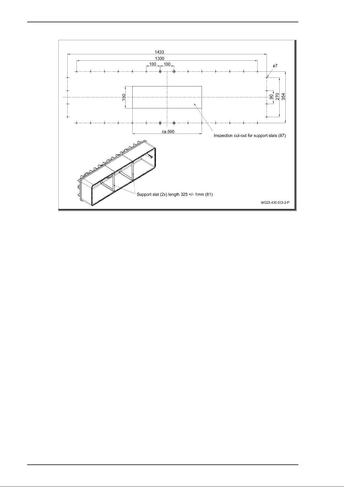
Pool cutout for concrete pools/formwork
Fig. 4
Table of contents
Other Speck pumpen Lighting Equipment manuals


Popular Lighting Equipment manuals by other brands


WAC Lighting
WAC Lighting LED-350MA03-RB instructions

Photonic
Photonic HPRL operating manual

Signtex
Signtex RAE-REC Series Installation instructions & user manual

Metz
Metz mecastudio TL-600 Operating instruction

RANCEO
RANCEO See Snake CL15 instruction manual

Honeywell
Honeywell MultiLED PRO Combi SET-10 instructions

unios
unios Echo Quick installation guide

ecolight
ecolight UC1034-BR2-12LF0-E instruction manual

Conrad
Conrad 31 82 73 operating instructions

Clas Ohlson
Clas Ohlson XY-BL3-20BT6 instruction manual

Cooper Lighting
Cooper Lighting WaveLinx Lite User and programming manual

Cooper Lighting
Cooper Lighting Corelite Class R2R installation instructions