manuals.online logo
Brands
  1. Home
  2. •
  3. Brands
  4. •
  5. Speco
  6. •
  7. Speakers System
  8. •
  9. Speco Nexus Contractor SP-5NXC/T User manual

Speco Nexus Contractor SP-5NXC/T User manual

SP-4NXC/T
SP-5NXC/T
SP-6NXC/T
Owner’s Manual for Models:
70/25V
Commercial
Speaker
Systems
200 New Highway Amityville, New York 11701 • Outside Metro NY: 1-800-645-5516
631-957-8700 • www.specotech.com
8.04
™™
Congratulations on your purchase of Speco Technologies’
Nexus Contractor™ 70/25 Volt Commercial Speaker
Systems!
Speco Technologies’ Nexus Contractor™ Commercial Speaker System Line offers premium quality
components and strong specification providing a network of sound and paging for the most
demanding commercial environments.
The high-end NXC Series features heavy-duty, industrial metal back cans that provides component
protection and safety while at the same time enhancing the speakers’ full-range bass sound as does
the speakers’ ported design.
Quick-snap terminal connects provide easy access and optimal angles for connecting speaker wire to
the NXC Series as a wattage selector dial makes transformer wattage setting as easy as a quick turn.
Added security loops mounted to the back can of the speakers allow for a support cable run.
Provided ceiling support brackets will complete a secure installation that will lend itself to countless
years of performance and reliability.
Nexus Contractor™ Commercial Speaker System Specifications:
Pre-construction:
Choosing Your Speaker Location and Pre-wiring the Job:
Carefully select areas of the ceiling where there are no obstructions, plumbing, heating/AC apparatus or
electrical wiring.
For sheetrock ceilings, use the enclosed C-Bracket as a cut out guide, tracing the inner dimensions of this
bracket on your sheetrock ceiling, then proceed to cut out the circle to establish mounting hole.
On drop ceiling installations where the ceiling tiles will not support the weight of the speaker, use
the accompanying pre-mounted brackets to support the weight of the speaker. Each bracket has two
elongated support brackets and a center C-Bracket that have dog-eared sides that rest on the elongated
support brackets and then are secured by the enclosed screws.
After selecting your brackets location, cut holes through the ceiling tile that line up perfectly with the
placement and diameter of the C-Brackets.
Upon finalizing speaker location and cutting holes, pre-run speaker wire through ceiling to be available
upon speaker installation.
Specifications:
• 4” Polypropylene Coated Woofer
with Rubber Surround
• 3/4” PEI Tweeter
• Frequency: 60Hz –20kHz
• 10 Watt RMS/ 30 Watt Max
• Sensitivity: 86 db 1w/1m
• Impedance: 8 ohms
• Transformer:
70/25 Volt Transformer Dial
• Transformer Settings:
10w/ 5w/2.5w/ 1.2w & 8 ohms
• Dimensions: 8” Dia x 8 1/2“ D
• Cut Out Dimension: 7” Dia
• Weight: 4.6 lbs.
• Quick-Snap Terminal Connects
• Metal Safety Loop for Securing
• Mounting Brackets Included
Specifications:
• 5.25” Polypropylene Coated Woofer
with Rubber Surround
• 3/4” PEI Tweeter
• Frequency: 50Hz –20kHz
• 60 Watts RMS/ 120 Watts Max
• Sensitivity 89 db 1w/1m
• Impedance: 8 ohms
• Transformer:
70/25 Volt Transformer Dial
• Transformer Settings:
60w/ 30w/ 10w/ 5w/ 2w & 8 ohm
• Dimensions: 9 3/4” Dia x 8 1/8 “ D
• Cut Out Dimension: 8 1/2” Dia
• Weight: 6.8 lbs.
• Quick-Snap Terminal Connects
• Metal Safety Loop for Securing
• Mounting Brackets Included
Item Code: SP-5NXC/T
5.25” 70/25V Commercial
Speaker System
Item Code: SP-6NXC/T
6.5” 70/25V Commercial
Speaker System
Specifications:
• 6.5” Polypropylene Coated Woofer
with Rubber Surround
• 3/4” PEI Tweeter
• Frequency: 50Hz –20kHz
• 60 Watts RMS/ 140 Watts Max
• Sensitivity: 90 db 1w/m
• Impedance: 8 ohms
• Transformer:
70/25 Volt Transformer Dial
• Transformer Settings:
60w/ 30w/ 10w/ 5w/ 2w & 8 ohm
• Dimensions: 10” Dia x 8 1/8 “ D
• Cut Out Dimension: 9” Dia
• Weight: 7.1 lbs.
• Quick-Snap Terminal Connects
• Metal Safety Loop for Securing
• Mounting Brackets Included
Item Code: SP-4NXC/T
4” 70/25V Commercial
Speaker System
Connecting and Mounting Your Speakers:
Please follow these directions for connecting and mounting your
Nexus Contractor™ Commercial Speaker System:
Easy Mount Tabs Quick-Snap
Terminal
Connect
3/4”
Punch
Out
Hole
Strain
Protector
Wattage
Tap Dial
Easy Mount Tabs
Adjusting Screws
Silver Wattage
Tap Dial Indicator
Terminal
Metal
Cover
Paint
Shield
™
Installation:
Wattage Selection
Note: It is important that before making any connections with the speaker terminals on your NXC Series
that your power source, amplifier and/or receiver, is completely turned off.
First, determine the purpose that your NXC Series will be used for by determining whether it will be
used in a 70 Volt, 25 Volt or 8 ohms application.
Remove your speaker systems from the carton and remove the paint shield that is over the face of each
speaker.
Once you have removed the paint shield and determined that your application is either is for 70 Volt or 25
Volt commercial use, you must determine which wattage tap setting best meets the need of the sound
environment your speaker will be utilized in.
Usually, a wattage tap dial sets at “1.2W” – “2.0W” will be utilized for background music in a quiet office
setting. The higher wattage taps “5.0W” – 60W” are utilized when a higher volume for the speaker is
needed to offset a louder environment. After determining your need, gently turn the wattage tap dial on
the faceplate of each speaker with a small flathead screwdriver so that the silver-colored indicator is
aligned with the desired wattage tap on the corresponding “70V” or “25V” side of the transformer dial.
Your transformer setting is then set and the NXC speaker will intuitively know whether it is receiving a
70 or 25 Volt run.
For an 8 ohms speaker requirement, turn dial tap so that the silver indicator aligns with the 8 ohms
indication on the dial. This automatically overrides the transformer within the unit.
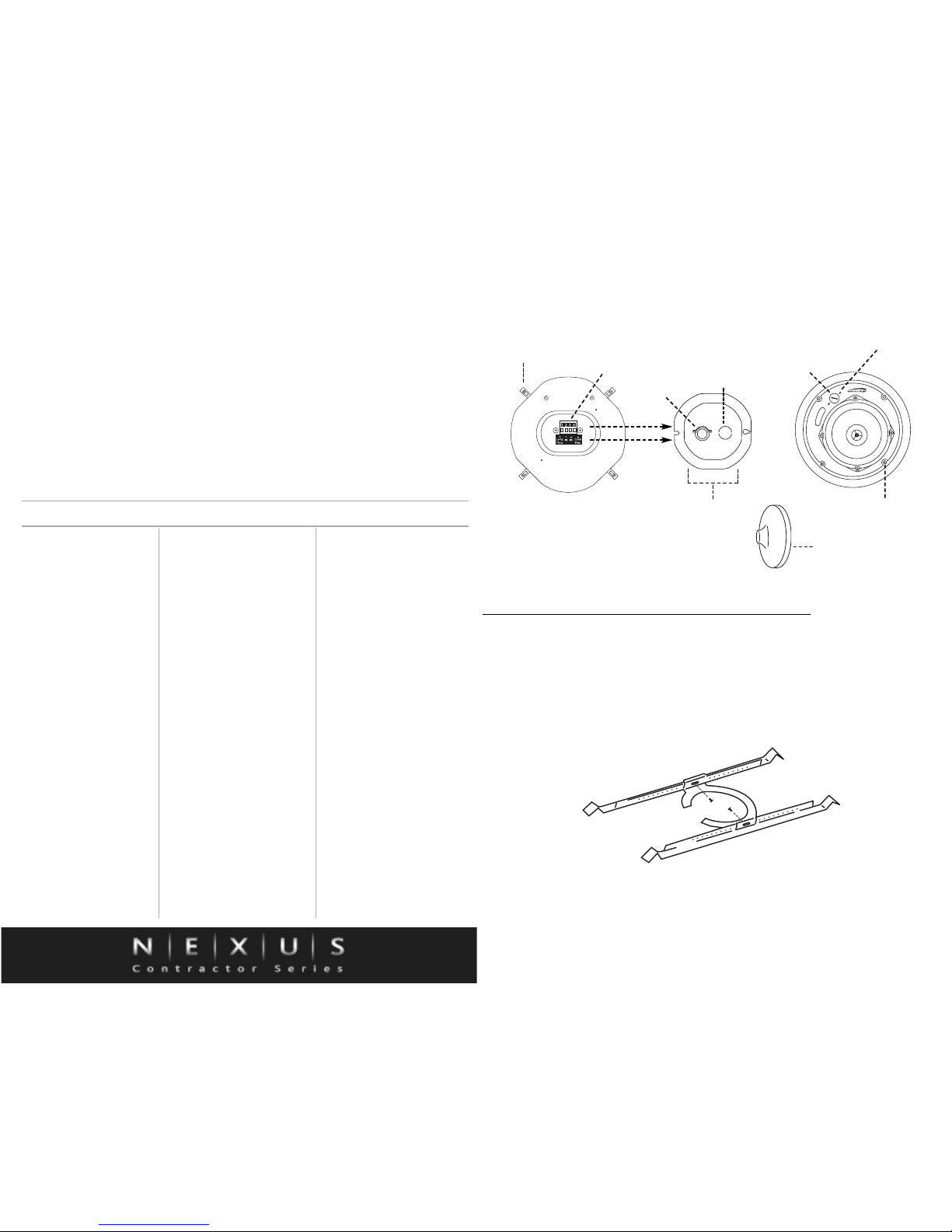
Connecting Speaker Wire
To correctly wire your speaker systems, carefully remove the terminal metal cover protecting the terminals
on the back of your speakers by unscrewing the fastened screws in each of the two corners. When the
terminal metal cover is removed, loosen the screws on the strain-protector portion of the terminal cover
and pass the speaker wire through the strain-protector.
After passing the pre-laid wire through the strain-protector, remove the gray-numbered quick-snap
terminal connect from the back of the speaker by slowly pulling it straight out of the terminals.
On desired Parallel Runs, use the positive wire entering from the amplifier to enter and leave through
terminal #2. The common wire running back to the amplifier should enter and leave through terminal #3
to wire your run as shown in the following example:
On desired Loop Through Runs, have the positive wire from amplifier enter through terminal # 2 and exit
through terminal #1, then have common wire running from other speakers in the run enter through termi-
nal #4, eventually heading back to the amplifier through terminal #3. See following diagram:
Once the wires are in, firmly tighten the small screws above each terminal until the wires are firmly
secured.
Upon securing, gently snap the quick-snap terminal connects back into place making sure it is lined up
properly and the text of the numbers on the quick-snap terminal connects match the same direction as the
text of the positive/negative indications on the back of the speaker for proper fitting.
Once the quick-snap terminal connect is in place, re-cover and the terminals section by securing the ter-
minal metal cover to its original location. Upon securing the terminal metal cover, faster the screws on the
strain-protector to secure and clamp down on the wires to prevent loosening during installation and
post-installation.
A 3/4” diameter punch out hole is also available on the terminal metal cover for installations where solid
conduit or flex pipe is needed. A pipe clamp is included as well for this purpose.
In addition, a metal safety loop accompanies the back of each speaker and is recommended for securing
a speaker run with a supporting cable.
After connecting each speaker, it is recommended that you quickly check the connections with sound prior
to final mounting installation to ensure that everything is installed properly and functioning well.
Installation:
Upon determining you have a strong wire connection with your NXC Series speakers, they must be
flush-mounted.
To install in a sheetrock ceiling, turn easy-mount tabs inward to the body of the speaker, carefully place
speaker in the diameter of the pre-cut whole and tighten the four mounting screwing on the outer rim of
the speaker faceplate until secure. This will cause the easy-mount tabs to clamp down behind the
sheetrock and secure the speaker.
On installations with drop ceilings, make sure your provide speaker brackets are firmly secure and
assembled in the ceiling, then insert the wired speakers with easy mount tabs by following the directions
in the preceding paragraph.
Please make absolutely certain that all speakers are securely mounted and that your selected site of
mounting can support the speaker weight indefinitely. SPECO TECHNOLOGIES ASSUMES NO
LIABILITY FOR MIS-INSTALLED OR MISPLACED SPEAKERS.
+
-
+
-
From Amplifier
Previous Speaker
To Next
Speaker
+
-
+
-
From Amplifier
Previous Speaker
To Next
Speaker
* Through this wiring method, if the quick-snap terminal connect is pulled out in the middle
of a speaker run, subsequent speakers will stay connected.
™
* Through this wiring method, if the quick-snap terminal connect is pulled out in the middle
of a speaker run, subsequent speakers will stay connected.
Painting:
If the need to paint your speaker is present, separately paint the speaker grilles letting thoroughly dry, and
use the paint guard shield to protect the face of the speaker while painting the speakers’ flush-mounted
rim.
Upon securing your speaker systems, replace the grilles back on the faceplate and you are finished to
enjoy your high-quality Nexus Contractor™ Series speakers.
Warranty:
Speco Technologies offers a limited 15-year warranty on their indoor speakers. Please reference the
enclosed warranty card for complete details of warranty.
Speco Technologies
200 New Highway
Amityville, New York 11701
631-957-8700
www.specotech.com
NOTES
30 or 60 Watt 4 Zone Amplifiers with
AM/FM Tuner and CD Player
Item Codes: P-30FACD, P-60FACD
(Also available in cassette version)
15, 30, 60, 120 Watt RMS Contractor
Series Amplifiers
Item Codes: PBM-15, PBM-30,
PBM-60 or PBM-120
Desktop MIC with XLR Connector
Item Code: MHL-5S
70/25V MA Series ABS Plastic
Enclosure Speakers
Item Codes: SP-5MA/T, SP-6MA/T
70/25V Commercial Speakers
Item Codes: G86TG, G86TCG (with
Volume Control)
70/25V 30 Watt Weatherproof Horn
Item Code: SPC-30RT
70/25 5.25" Outdoor Speakers
Item Codes: SP-5AWD/T (Black),
SP-5AWD/T-W (White)
Available in 6.5” also
70/25V Rock Speakers
Item Code: SP-RK65CB/T
(Brown), SP-RK65CG/T (Granite)
Speco Technologies’Top Selling Commercial Items

This manual suits for next models

7

Other Speco Speakers System manuals

Speco SP-100 User manual

Speco

Speco SP-100 User manual

Speco CSi/SPECO SP-RK65CB/T User manual

Speco

Speco CSi/SPECO SP-RK65CB/T User manual

Speco SP-625BB User manual

Speco

Speco SP-625BB User manual

Speco SP-5MA User manual

Speco

Speco SP-5MA User manual

Speco SP-300 User manual

Speco

Speco SP-300 User manual

Speco NXC Series User manual

Speco

Speco NXC Series User manual

Speco CSi/SPECO SP-250W User manual

Speco

Speco CSi/SPECO SP-250W User manual

Speco SP-RK65CG/T User manual

Speco

Speco SP-RK65CG/T User manual

Speco DMS-2 User manual

Speco

Speco DMS-2 User manual

Speco MA Series User manual

Speco

Speco MA Series User manual

Speco DMS-3TS User manual

Speco

Speco DMS-3TS User manual

Speco SPCDC6 User manual

Speco

Speco SPCDC6 User manual

Speco SP-5MA/T User manual

Speco

Speco SP-5MA/T User manual

Speco SP6MAT User manual

Speco

Speco SP6MAT User manual

Popular Speakers System manuals by other brands

iLive ITBSW397 user guide

iLive

iLive ITBSW397 user guide

OSD Audio NERO SB42 user guide

OSD Audio

OSD Audio NERO SB42 user guide

Alpine SPX-Z18T owner's manual

Alpine

Alpine SPX-Z18T owner's manual

Gogen TAS 930 user manual

Gogen

Gogen TAS 930 user manual

Pioneer PDP-S58 operating instructions

Pioneer

Pioneer PDP-S58 operating instructions

Arion ET-AR504LR-BK User instructions

Arion

Arion ET-AR504LR-BK User instructions

JVC CA-TD55R instructions

JVC

JVC CA-TD55R instructions

LG MUSIC FLOW SJ8 installation guide

LG

LG MUSIC FLOW SJ8 installation guide

JVC SP-X103 instructions

JVC

JVC SP-X103 instructions

Impecca S6 manual

Impecca

Impecca S6 manual

AEG BSS 4807 instruction manual

AEG

AEG BSS 4807 instruction manual

MAJORITY BOWFELL Instruction guide

MAJORITY

MAJORITY BOWFELL Instruction guide

Advanced Native Technologies BHS Series user manual

Advanced Native Technologies

Advanced Native Technologies BHS Series user manual

Ibiza sound Port9CD-VHF user manual

Ibiza sound

Ibiza sound Port9CD-VHF user manual

VESTEL OPS-KL756V user manual

VESTEL

VESTEL OPS-KL756V user manual

LG LAS160B owner's manual

LG

LG LAS160B owner's manual

AUDAC IMEO2/B user manual

AUDAC

AUDAC IMEO2/B user manual

Samsung HW-Q70T Full manual

Samsung

Samsung HW-Q70T Full manual

manuals.online logo
manuals.online logoBrands
  • About & Mission
  • Contact us
  • Privacy Policy
  • Terms and Conditions

Copyright 2025 Manuals.Online. All Rights Reserved.