Spectec XP2 Series User manual
THUNDERBIRD INTERNATIONAL CORPORATION
P.O. Box 360, Emigrant, MT 59027-0360
406-333-4967 ∙ FAX 406-333-4259
INSTRUCTION MANUAL
XP2 Series, Conduit Style
Active Speed Sensors 85047X
Engineering Approval: Date: 03-18-2019 Revision: 1
PROPRIETARY, COPYRIGHTED INFORMATION DO NOT DUPLICATE OR DISTRIBUTE TO THIRD PARITES UNLESS AUTHORIZED BY SPECTEC
Approval agency controlled document. Do not alter without authorization. Page 1 of 3
Introduction
SPECTEC's Explosion Proof / Flame Proof sensors are designed for
installation in hazardous locations. They are offered in a wide
variety of configurations. See the XP2 Bulletin for specifications
and configuration options.
Marking
Unit Type No.: XP2-xxxxxx
Date Code: WW/YY (Week/Year)
Conduit Size: 1/2- NPT or M20x1.5
Electrical Rating: xx to xx V DC @ ≤xx mA (marked according to
sensor type, see XP2 Bulletin)
Codes: CL I DIV 1 GP ABCD T6...T3
CL I ZN 1 AEx/Ex db IIC T6...T3 Gb
T3@ Ta = -50°C...+140°C (marked)
T4@ Ta = -50°C...+112°C
T5@ Ta = -50°C...+77°C
T6@ Ta = -50°C...+62°C
II 2 G Ex db IIC T6...T3 Gb
T3@ Ta = -55°C...+140°C (marked)
T4@ Ta = -55°C...+112°C
T5@ Ta = -55°C...+77°C
T6@ Ta = -55°C...+62°C
Certificate No.: FM16US0288X & FM16CA0147X
FM16ATEX0086X & IECEx FMG 16.0035X
CE Marking: 2809
Warnings: SEAL ALL CONDUITS WITHIN 18 INCHES
DISCONNECT POWER BEFORE OPENING
FERMER TOUS LES CONDUITS SOUS 18 POUCES
(.45m) MAXIMUM
DÉBRANCHER L’ALIMENTATION ELECTRIQUE
AVANT L'OUVERTURE
Specific Conditions of Use
1. Refer to these instructions for complete temperature ratings
and suitability.
2. No external grounding is provided. The sensor must be
mounted as part of a bonded structure.
3. The wiring shall be mechanically protected as required by the
applicable area electrical code and shall be terminated in a
suitable terminal or junction facility.
Warnings
1. A poured conduit seal must be applied within 18 inches
(0.45m) of the sensor.
2. Disconnect power before opening or removing the sensor.
Compatibility
Refer to the listed certification and temperature ratings for
suitability. The intended environmental and operating conditions
should be verified to be in compliance with these ratings.
Housing: 303 or 304 series Stainless Steel
Cable: PTFE insulated (Polytetrafluoroethylene)
or FEP insulated (Fluorinated ethylene propylene)
NOTE: For Canadian installations, only female NPT or metric entries
are permissible per CSA C22.2 No. 0.5 & 30.
Type Approval Standards
The XP2 product series have certificates issued by FM Approvals
and have been approved to the following standards:
United States of America (USA) Standards:
FM Class 3600:2011 General Requirements
FM Class 3615:2006 Explosionproof General Requirements
FM Class 3810:2005 General Requirements
ANSI/ISA61010-1:2012 Safety General Requirements
ANSI/ISA60079-0:2013 General Requirements
ANIS/UL60079-1:2015 Flameproof Enclosures 'd'
Canadian Standards:
CSA C22.2 No. 0.4-04: R2013 Bonding of Electrical Equipment
CSA C22.2 No. 0.5:2016 Threaded Conduit Entries
CSA C22.2 No. 61010-1:2012 Safety General Requirements
CSA C22.2 No. 30-M1986:R2012 Explosion-proof Encl.
CSA C22.2 No. 60079-0:2012 General Requirements
CSA C22.2 No. 60079-1:2016 Flameproof Enclosures 'd'
ATEX Standards:
EN60079-0:2012 + A11:2013 General Requirements
EN60079-1:2014 Flameproof Enclosures 'd'
IECEX Standards:
IEC60079-0:2011 General Requirements
IEC60079-1:2014 Flameproof Enclosures 'd'
Installation Requirements
The installation shall be carried out by suitably trained personnel.
The sensor must be installed in accordance with the latest issue of
the following standards:
US installations:
follow the National Electrical Code ANSI/NFPA 70,
Canadian installations:
follow the Canadian Electrical Code CSA C22.1,
ATEX installations: follow EN 60079-14,
IECEx installations: follow IEC 60079-14.
The installation must also be in accordance with any local codes
and national regulations that apply.
JE
Approved May 9th, 2019
THUNDERBIRD INTERNATIONAL CORPORATION
P.O. Box 360, Emigrant, MT 59027-0360
406-333-4967 ∙ FAX 406-333-4259
INSTRUCTION MANUAL
XP2 Series, Conduit Style
Active Speed Sensors 85047X
Engineering Approval: Date: 03-18-2019 Revision: 1
PROPRIETARY, COPYRIGHTED INFORMATION DO NOT DUPLICATE OR DISTRIBUTE TO THIRD PARITES UNLESS AUTHORIZED BY SPECTEC
Approval agency controlled document. Do not alter without authorization. Page 2 of 3
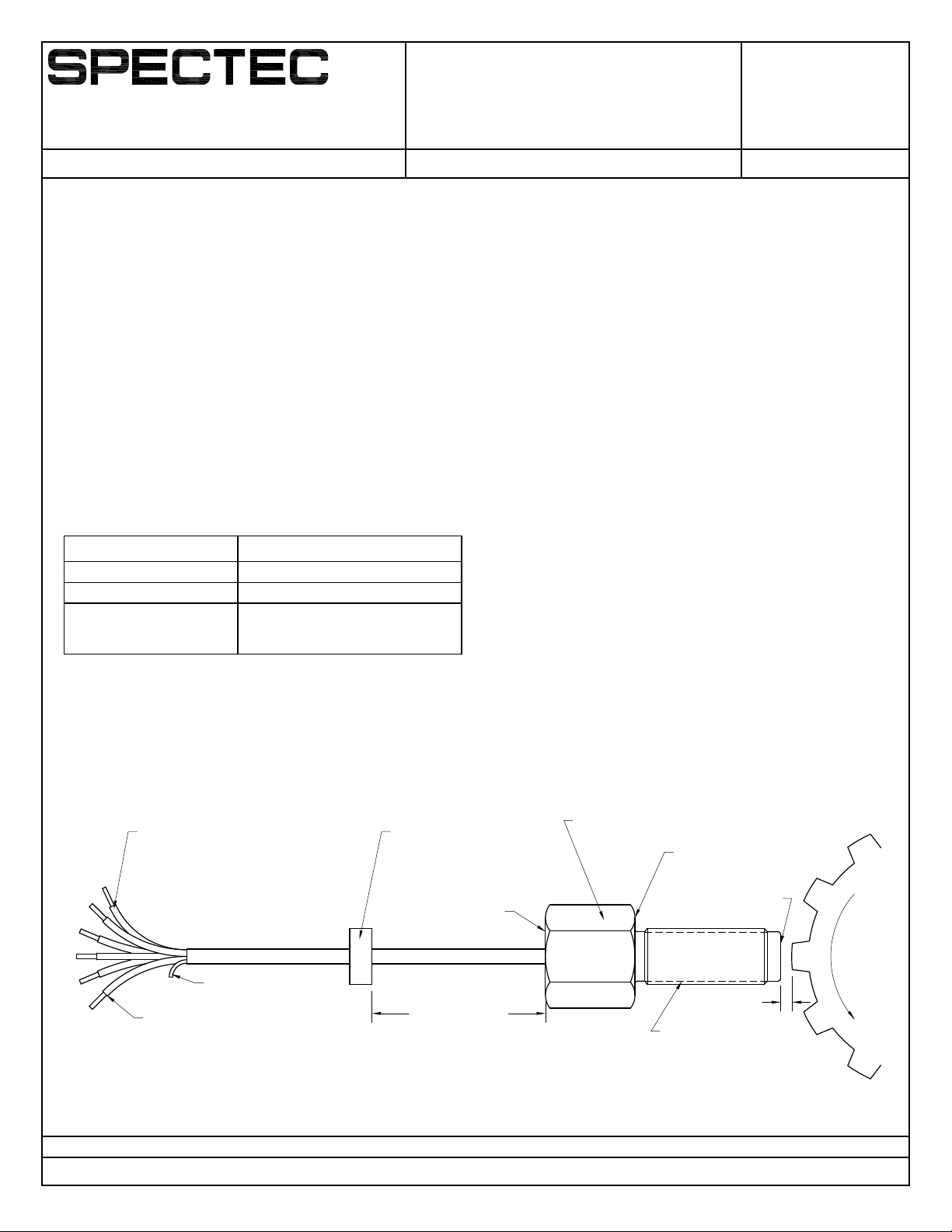
Installation Procedure
Mounting
1. Thread the sensor into a suitable bracket or housing with the
Sensing Surface aimed toward the Target.
2. Set the Air Gap (shortest distance from Target to Sensing
Surface) at a typical distance of .020" to .040" (0.5 to 1.0mm).
Be sure to account for any eccentricity of the Target to avoid
damage to the sensor which can affect safety. This distance
should be >.010" (0.25mm) over the eccentricity of the Target.
NOTE: Rotate the alignment mark to point at the gear for Dual
Output and Directional Sensor Types.
3. Securely lock the sensor at the correct Air Gap using a jam
nut or other suitable means. Do not over torque the mounting
thread. Recommended tightening torque is listed below.
4. A poured conduit seal must be applied within 18 inches
(0.45m) of the sensor.
Wiring
The wiring is provided as either shielded cable or individual leads.
Make all wire connections before applying power to the circuit.
The appropriate DC (direct current) power supply for each Sensor
Type is detailed on the XP2 Bulletin and marked on each sensor.
The wiring shall be mechanically protected as required by the
applicable area electrical code and shall be terminated in a
suitable terminal or junction facility.
Control Equipment connected to this equipment must not use or
generate more than 250V.
Wire Color codes are as follows:
Red - + Power, DC Voltage positive
Black - – Common, DC Voltage negative
White - Signal A output, referenced from Common
Green - Internal Housing Ground (connect to earth)
Bare - Cable shield (connect to instrument ground)
Yellow - Signal B output, as applicable
Blue - Direction Signal output, as applicable
Cable and individual leads temperature range is -55°C to +200°C.
Earthing / Grounding
The green (or green with yellow stripe) wire of the sensor is an
internal connection to the metal housing. This wire must be
connected to an earth ground to maintain the safety of the
sensor. Additionally, no external ground is provided so the sensor
must be mounted as part of a bonded structure.
Air Gap
Classification
Marking
Housing Ground
MUST BE TIED TO EARTH
GROUND
Green or Green with Yellow
(May be included as separate lead)
* 18" (.45m)
MAX.
* POURED
CONDUIT SEAL
Power and
Signal Leads
Cable Shield (Bare)
Directional Mark
(only on some units)
Target
(forward)
Sensing Surface
Mounting
Thread
Mounting Thread Recommended Maximum Torque
1/2-20 UNF, M12x1-6g 11.0 lbf·ft (14.9 N·m)
5/8-18 UNF, M16x1.5-6g 19.0 lbf·ft (25.7 N·m)
11/16-24 UNEF, 3/4-16 UNF,
3/4-20 UNEF,
M18x1.0-6g, M18x1.5-6g
33.0 lbf·ft (44.7 N·m)
JE
Conduit
Thread
* A POURED CONDUIT SEAL MUST BE APPLIED
WITHIN 18" (0.45m) MAXIMUM OF THE
SENSOR
Approved May 9th, 2019

THUNDERBIRD INTERNATIONAL CORPORATION
P.O. Box 360, Emigrant, MT 59027-0360
406-333-4967 ∙ FAX 406-333-4259
INSTRUCTION MANUAL
XP2 Series, Conduit Style
Active Speed Sensors 85047X
Engineering Approval: Date: 03-18-2019 Revision: 1
PROPRIETARY, COPYRIGHTED INFORMATION DO NOT DUPLICATE OR DISTRIBUTE TO THIRD PARITES UNLESS AUTHORIZED BY SPECTEC
Approval agency controlled document. Do not alter without authorization. Page 3 of 3
Sensor Type Notes
DIGISPEC Hall Effect Sensor
H Type Magnet Actuated
This zero speed sensor is triggered by a magnet or a magnetic
field and offers sensing over larger air gaps. This Sensor Type is
typically used on gear meters or magnet wheels. Dual and
directional output options are also available. It is available in the
following types:
Ho - Omnipolar (north or south pole activation)
Hs - South pole only activation
Hn - North pole only activation
H - Bipolar Latch (requires alternating north and south poles)
HF Type Gear Actuated
This zero speed sensor is triggered by a ferrous metal target (bolt,
keyway, or typically a gear tooth). The HF Sensor Type is usually
used in motor RPM and camshaft timing. Dual and directional
output options are also available. An HFd Type differential sensor
(for high vibration environments) is also available as an option.
DIGISPEC Magnetic VRS Sensor
This Sensor Type also requires a ferrous metal target. A smaller air
gap and a minimum surface speed are required to operate
properly. It is usually used on flowmeters because it can detect
more precisely and with lower magnetic drag than HF Type
sensors.
DIGISPEC RF Sensor
This Sensor Type operates on the Eddy Current principle and
interacts with a ferrous or aluminum target without imposing a
magnetic drag. SPECTEC's RF sensors are specifically designed for
precision Turbine Flowmeters where no magnetic drag can be
tolerated. They are also used for high pressure applications with
the ability to sense through a non-magnetic stainless steel wall.
They also function close to zero speed, but are typically limited to
5kHz maximum frequency.
See the XP2 Bulletin for details on the supply voltage range,
frequency range, and maximum Air Gap for each Sensor Type.
Operation and Usage
Operation
1. Verify that the sensor is properly mounted and all electrical
connections are made (including earthing).
2. Switch on the DC supply voltage and allow the Target to
move. The sensor should now produce an output signal.
3. If a signal is not produced, verify that the Target is moving
faster than the minimum detectable frequency of the Sensor
Type. If a signal is still not produced, follow the steps in the
Adjustment process detailed below.
4. The output signal will switch state when a target enters or
leaves the detection area. For the NPN output options, the
signal will be High (5V, 10V, or the supply voltage) without a
target in the detection area. The output will switch Low when
a target enters the detection area. For the PNP output option,
the output will be inverted from the above.
5. Directional Hall Effect sensors will output a High signal on the
Direction Output when the target is rotating in the Forward
direction. If the correct signal is not produced, follow the
Directional Alignment process detailed below.
Adjustment
1. Stop the rotation or movement of the Target.
2. Loosen the jam nut or other locking device.
3. Decrease the Air Gap by .005 - .010" (0.12 - 0.25mm). Be sure
to account for any eccentricity in the rotation and movement
of the Target. Otherwise the sensor may be damaged.
4. Re-tighten the jam nut or locking device and check again for
an output signal.
Directional Alignment (only applicable to some Sensor Types)
1. The Target should approach the Directional Mark when
moving in the forward direction. However, with smaller targets
the alignment may need adjusted.
2. Loosen the jam nut or other locking device.
3. Rotate the Directional Mark of the sensor slightly away from
the approaching Target until the signal has the correct 90°
electrical phasing (easily viewed on an oscilloscope).
4. Re-tighten the jam nut or locking device and check again for
an output signal.
Removal
Removing or Uninstalling the sensor is the reverse of the Installation
Procedure.
WARNING: Before separating connections, the target must be
stopped and the sensor should be de-energized.
Service and Repair
The sensor cannot be serviced or repaired in the field. Please
contact sales to purchase a replacement.
WARNING: Do not remove plugs, fittings, cable glands, or blanking
elements installed by the manufacturer.
JE
Approved May 9th, 2019


