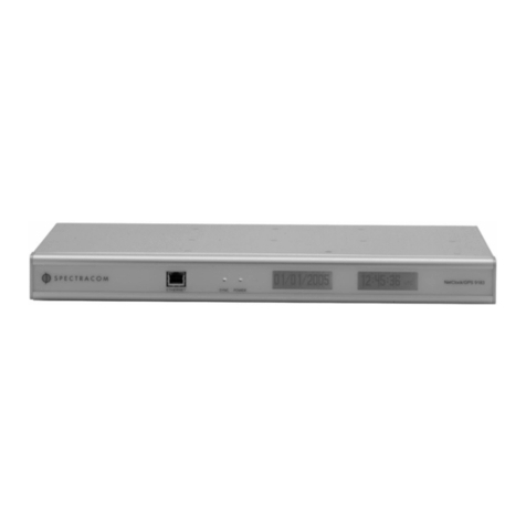
Spectracom TimeView 230 User manual

TimeView 230 Display Clock
Model 8175
Instruction ManualInstruction Manual
Instruction ManualInstruction Manual
Instruction Manual
Spectracom CorporationSpectracom Corporation
Spectracom CorporationSpectracom Corporation
Spectracom Corporation
101 Despatch Drive
East Rochester NY 14445 USA
PHONE: +1.585.381.4827 FAX: +1.585.381.4998
wwwwww
wwwwww
www.spectracomcorp.com [email protected].spectracomcorp.com [email protected]
.spectracomcorp.com [email protected]
Rev. 1.5
September 2002
CopyrightCopyright
CopyrightCopyright
Copyright ©2002 Spectracom Corporation.2002 Spectracom Corporation.
2002 Spectracom Corporation.2002 Spectracom Corporation.
2002 Spectracom Corporation.
All rights reserved. Contents of this publication may not be reproduced
in any form without the written permission of Spectracom Corporation.

LIMITED WARRANTY AND WARRANTY CLAIMS:
Spectracom warrants each new product manufactured
and sold by it to be free from defects in material,
workmanship, and construction, except for batteries,
fuses, or other material normally consumed in operation
that may be contained therein, for five years after
shipment to the original purchaser (which period is
referred to as the “warranty period”). This warranty
shall not apply if the product is used contrary to the
Spectracom®,NetClock®, TimeTap®, TimeTalkand TimeBurst
are trademarks of Spectracom Corporation.
All other products are identified by trademarks of their respective companies or organizations.
Time of Day ProductTime of Day Product
Time of Day ProductTime of Day Product
Time of Day Product
Five Year Warranty
instructions in its manual or is otherwise subjected to misuse, abnormal
operations, accident, lightning or repairs or modifications not per-
formed bySpectracom. Spectracom is not responsible for products that
it does not manufacture.
Software and receiver modules not manufactured by Spectracom and
any cable assemblies and adapters are warranted for one year from
date of shipment and subject to exceptions listed above.
Spectracom’s obligation under this warranty is limited to in-factory
service and repair, at Spectracom’s option, of the product or the
component thereof which is found to be defective. If in Spectracom’s
judgment the defective condition in a Spectracom product is for a cause
listed above for which Spectracom is not responsible, Spectracom will
make the repairs or replacement of components and charge its then
current price, which buyer agrees to pay.
Spectracom shall not have any warranty obligations if the procedure for
warranty claims is not followed. Notify Spectracom of the claim with full
information as to the claimed defect. Spectracom products shall not be
returned unless a return authorization number is issued by Spectracom.
Spectracom products must be returned with the description of the
claimed defect and identification of the individual to be contacted if
additional information is needed. Spectracom products must be
returned properly packed with transportation charges prepaid.
EXCEPT FOR THE LIMITED WARRANTY STATED ABOVE, SPECTRACOM
DISCLAIMS ALL WARRANTIES OF ANY KIND WITH REGARD TO SPECTRA-
COM PRODUCTS OR OTHER MATERIALS PROVIDED BY SPECTRACOM,
INCLUDING WITHOUT LIMITATION ANY IMPLIED WARRANTY OR
MERCHANTABILITY OR FITNESS FOR A PARTICULAR PURPOSE.
Spectracom shall have no liability or responsibility to the original
customer or any other party with respect to any liability, loss, or damage
caused directly or indirectly by any Spectracom product, material, or
software sold or provided by Spectracom, replacement parts or units, or
services provided, including but not limited to any interruption of
service, excess charges resulting from malfunctions of hardware or
software, loss of business or anticipatory profits resulting from the use
or operation of the Spectracom product or software, whatsoever or
howsoever caused. In no event shall Spectracom be liable for any
direct, indirect, special or consequential damages whether the claims
are grounded in contract, tort (including negligence), or strict liability.
EXTENDED WARRANTY COVERAGEEXTENDED WARRANTY COVERAGE
EXTENDED WARRANTY COVERAGEEXTENDED WARRANTY COVERAGE
EXTENDED WARRANTY COVERAGE
Extended warranties can be purchased for additional periods beyond
the standard five year warranty. Contact Spectracom during the last
year of the standard five year warranty for extended coverage.
6/1/98

TABLE OF CONTENTS
SECTION1 GENERALINFORMATION
1.0 Introduction ................................................................. 1-1
1.1 Features...................................................................... 1-2
1.2 WarrantyInformationandProductSupport .................. 1-2
1.3 ManualErrataandSpecialDocumentation .................. 1-3
1.4 Unpacking ................................................................... 1-3
1.5 Specifications.............................................................. 1-4
1.5.1 RS-485Input 1-4
1.5.2 RS-485Repeater 1-5
1.5.3 UserSelectableOptions 1-5
1.5.4 Power 1-5
1.5.5 PhysicalandEnvironmental 1-5
SECTION 2 INSTALLATION
2.0 Introduction ................................................................. 2-1
2.1 MountingInstructions .................................................. 2-1
2.2 PreparationforUse...................................................... 2-3
2.2.1 TimeZoneOffset 2-3
2.2.2 12-or24-HourDisplay 2-5
2.2.3 SynchronizationSource 2-5
2.2.4 Termination 2-5
2.2.5 Brightness Adjust 2-5
2.3 SynchronizationConnection ........................................ 2-6
2.3.1 ConnectiontoNetClock/2 2-6
2.3.2 Connection to GPS Synchronized Clocks
orTimeBridge ................................................. 2-7
2.4 InterconnectionInformation.......................................... 2-8
2.4.1 RS-485Guidelines ......................................... 2-8
2.4.2 RS-485Repeater .......................................... 2-14
2.5 ConnectiontoaComputer......................................... 2-16
2.6 ManualSetProcedure............................................... 2-17
2.6.1 ManualSetProcedure 2-18
SECTION3 OPERATION
3.0 Introduction ................................................................. 3-1
3.1 Display........................................................................ 3-1
3.1.1 FaultIndications 3-2
3.2 RearPanelFunctions.................................................. 3-2
3.2.1 RS-485Interface 3-4
3.2.2 Manual Set Switches 3-5
3.2.3 Power 3-5
3.2.4 ConfigurationSwitches 3-5

LISTOFTABLESANDILLUSTRATIONS
TABLE1-1 ANCILLARYKIT .......................................................1-4
TABLE2-1 COMMONOFFSETVALUES...................................2-4
TABLE2-2 TIMEZONESWITCHSETTINGS..............................2-4
TABLE2-3 CABLESOURCESFORRS-485LINES
OVER1500FEET ....................................................2-9
TABLE2-4 CABLESOURCESFORRS-485LINES
UNDER1500FEET ..................................................2-9
TABLE3-1 TIMEZONEOFFSETS .............................................3-7
FIGURE1-1 MODEL8175TIMEVIEW230...................................1-1
FIGURE2-1 DUPLEXMOUNTINGHOLES ...................................2-2
FIGURE2-2 NETCLOCK/2REMOTEOUTPUTCONNECTOR........2-6
FIGURE2-3 CONNECTIONTONETCLOCK/2 ..............................2-7
FIGURE2-4 GPSMASTERCLOCKANDTIMEBRIDGE
CONNECTORS.........................................................2-7
FIGURE2-5 ONE-WAYBUSINSTALLATION.............................2-12
FIGURE2-6 SPLITBUSINSTALLATION ....................................2-13
FIGURE2-7 INSTALLATIONNOTUSING
REPEATEROUTPUT .............................................2-15
FIGURE2-8 REPEATEROUTPUTUSAGE................................2-15
FIGURE2-9 COMPUTERCONNECTION....................................2-16
FIGURE2-10 MULTIPLECLOCKCONNECTION..........................2-17
FIGURE3-1 MODEL8175DISPLAY ............................................3-1
FIGURE3-2 MODEL8175REARPANEL ....................................3-3
FIGURE3-3 RS-485TERMINALBLOCK ......................................3-4
FIGURE3-4 MANUALSETSWITCHES .......................................3-5
FIGURE3-5 CONFIGURATIONDIPSWITCH ...............................3-6

GENERAL INFORMATION
1.0 INTRODUCTION
The Spectracom®Model 8175 TimeView 230, shown in
Figure 1-1, is a synchronized display clock. TimeView 230
features2.3inchLEDdigitswhichcanbeviewedfrom75feet
away. Theclockdisplaystraceabletimewhenconnectedtoa
NetClock®MasterClock. Thedisplayisconfigurablefor12-or
24-hourtimeformatandtimezoneoffsets.
TimeView230displaysmayalsosynchronizetoahostcom-
puterrunninganetworktimekeepingsystem,orsetmanually
forstand-aloneoperation.
FIGURE 1-1 MODEL 8175 TIMEVIEW 230
Page 1-1
TimeView 230

1.1 FEATURES
TheSpectracomTimeView230offersthesefeatures:
* Displays traceable time when connected to a NetClock
Master Clock. Clocks may also be synchronized from a
computerorsetmanually.
* Automaticdataformatandbaudratedetectionmakesset
upandinstallationeasy.
* Configurable display for 12- or 24-hour format and time
zoneoffsets.
* Large 2.3 inch display digits offer exceptional
visibility.
1.2 WARRANTY INFORMATION AND
PRODUCT SUPPORT
Findwarrantyinformationontheinsidecoverofthismanual.
Shoulditbecomenecessarytoexercisethewarranty,contact
SpectracomCorporationtoobtainareplacementorservice.
Spectracomcontinuouslystrivestoimproveitsproductsand
greatly appreciates any customer feedback. Please direct
anycommentsorquestionsregardingapplication,operation,
or service to Spectracom’s Customer Service Department.
Customer service is available Monday through Friday from
8:00 AM to 5:00 PM Eastern time at 585-381-4827.
Inaddition,pleasecontactcustomerservicetoobtainaReturn
Material Authorization Number (RMA#) before
returning any device to Spectracom Corporation. Please
providetheserialnumberandfailuresymptoms.
Page 1-2

Transportation to the factory is to be prepaid by the
customer.
1.3 MANUAL ERRATA AND
SPECIAL DOCUMENTATION
Informationconcerningmanualcorrectionsorchangesmade
totheTimeViewarefoundontheerratasheet located at the
rearofthismanual.
Spectracom will make equipment modifications upon
special request. The documentation associated with any
specialis also located in theback of this manual.
1.4 UNPACKING
Upon receipt,carefullyexaminethecartonanditscontents. If
thereisdamagetothecarton,whichresultsindamagetothe
unit,contactthecarrierimmediatelysoitsrepresentativemay
witness such damage. Failure to report shipping damage
immediately may forfeit any claim against the carrier. In
addition,notifySpectracomofshippingdamageorshortages
toobtain a replacement or repair services.
EachModel8175isshippedwithaninstructionmanualandan
ancillarykit. Table1-1liststheitemsincludedintheancillary
kit. Checkthatall itemshavebeenreceived.
Page 1-3

Page 1-4
TABLE 1-1 ANCILLARY KIT
1.5 SPECIFICATIONS
This section lists the specifications for the Model 8175
TimeView 230.
1.5.1 RS-485 Input
Connector: 6-position removable terminal
block(supplied)
InputSignal: RS-485 ASCII data stream in
Format0or 1fromtheNetClock
MasterClockorComputer
BaudRate: 300 to 9600; automatic bit rate
detectionwithNetClockoperation.
9600 baud with computer set
operation.
Max.CableLength: 4000feet(1.2km)usingshielded
twisted pair
InputImpedance: Switch Selectable, 120 ohm
terminationor highimpedance.
ytitnauQrebmuNtraPnoitpircseD
145000TCAV5.61retpadACA
160031PkcolBlanimreTnoitisop-6
21000DHrohcnAcitsalP
26100-0001-001HlateMteehS,"1x01#,wercS
180086snoitcurtsnIgnitnuoMweiVemiT

TransientProtection: Diode protected from spikes ex-
ceeding +12 VDC and -7 VDC.
1.5.2 RS-485 Repeater
OutputSignal: Regenerated RS-485 signal of
appliedinputdatastream
MaxLoading: 32 devices
1.5.3 UserSelectableOptions
TimeView 230 switches and controls select the following
options: 12- or 24-hour display format, time zone offsets,
display intensity, time set from NetClock Master Clock,
computer,ormanuallyentered,andRS-485termination.
1.5.4 Power
PowerSource: UL listed AC power adapter (sup-
plied)
Input: 115 VAC ±10%, 60 Hz, 14 watts
Output: 16.5 VAC, 600 mA
Connector: Barrel,5.5mmO.D.,2.1mmI.D.
1.5.5 Physical and Environmental
Digit Size: 2.3"hoursandminutes
1" seconds
OverallSize: 5" H x 12"W x 2.9" D
WallMount: 8"centers
Weight: 2.2lbs.
Temperature: 0°to 50°C operating range
Page 1-5

Page 2-1
INSTALLATION
2.0 INTRODUCTION
This section describes the TimeView 230 mounting, switch
set-up,connectiontoaNetClockorcomputersynchroni-zation
sourceandmanualsetoperation.
2.1 MOUNTING INSTRUCTIONS
Theancillarykitincludesscrewsandplasticanchorsforwall
mountingtheclock. ToolsneededformountingareaPhillips
screwdriveranda 1/4"drill.
TimeViewisdesignedtomountoveraduplexoutlettoconceal
thepoweradapteranddatacables. For instal-lationswhere
this is not possible, notches are provided along the top and
bottomedgesforroutingpoweranddatacables.
ToinstallTimeViewoveraduplexoutlet,layareferenceline
over the cover plate as shown in Figure 2-1. Drill two 1/4"
holes,eightinchesapart,centeredovertheoutlet.

FIGURE 2-1 DUPLEX MOUNTING HOLES
NOTE:When hanging the clock, use the top
two cover screws as a guide for locat-
ing the mounting holes.
Page 2-2

Page 2-3
2.2 PREPARATION FOR USE
This section describes the configuration selections for the
Model 8175 TimeView 230. The rear panel 10-position DIP
switchselectstheclockoptions. TheTimeView230isfactory-
shipped for 24-hour display; no time zone offsets, NetClock
synchronization,andRS-485terminationoff.
2.2.1 Time Zone Offset
Thetimezoneoffsetfeatureallowsclockssynchronizedtoa
NetClockorcomputertodisplaytimeinalternatetimezones.
The selected time zone offset value is subtracted from the
appliedinputdatastream. DIPswitches1through5enterthe
binaryequivalentoftheoffsetvalueof0to23. Table2-1lists
commonoffsetvaluesfromaGreenwichMeanTime(GMT)or
CoordinatedUniversalTime (UTC)sourceduringperiods of
Standardtimeand DaylightSavingTime. Table2-2 liststhe
DIP switch settings for the offset values shown in Table 2-1.
See Section 3.2.4 for a complete list of offset and switch
settings.
NOTE:Typically the Spectracom Master Clock
is configured to provide local time. This
eliminates the need to enter additional
time zone offsets into the TimeView 230.
Place DIP switches 1 through 5 in the OFF
position when time zone offsets are not
required.

TIME ZONE STANDARD TIME
(October-April)
DAYLIGHT SAVING
TIME
(April-October)
Atlantic 4 3
Eastern 5 4
Central 6 5
Mountain 7 6
Pacific 8 7
TABLE 2-1 COMMON OFFSET VALUES
OFFSET
VALUE DIP SWITCH NUMBER / SETTING
12345
0OFF OFF OFF OFF OFF
3ON ON OFF OFF OFF
4OFF OFF ON OFF OFF
5ON OFF ON OFF OFF
6OFF ON ON OFF OFF
7ON ON ON OFF OFF
8OFF OFF OFF ON OFF
TABLE 2-2 TIME ZONE SWITCH SETTINGS
NOTE:Place DIP switches 1 through 5 in the OFF
position when time zone offsets are not
required.
Page 2-4

Page 2-5
2.2.2 12- or 24-Hour Display
TheTimeView230candisplaytimeina12-or24-hourformat.
Place DIP switch 6 in the ON position for 12-hour display
formatandOFFfor24-hourtimedisplay.
2.2.3 Synchronization Source
DIPswitchnumber7selectsthesourceofthesynchronizingdata
stream. Placeswitch7intheOFFpositionwhentheTimeView
isconnectedtoaNetClockMasterClock. Placeswitch7inthe
ONpositionforcomputersetapplications.
2.2.4 Termination
TheendsofanRS-485transmissionlinemustbeterminatedto
preserve the signal waveform and prevent reflections. The
TimeView230terminationswitch,DIPswitch10,terminatesthe
RS-485 data bus into 120 ohms. Place switch 10 in the ON
positionwhentheclockisinstalledattheendoftheRS-485data
bus. Otherwise,placethisswitchintheOFFposition. Referto
Section2.4foradditionalinformationontermination.
2.2.5 BrightnessAdjust
The display brightness is adjustable to suit various lighting
conditions. Thebrightnesspotentiometerisaccessedthrough
the hole in the lower right corner of the display. A small flat-
bladed screw driver is required.

Page 2-6
2.3 SYNCHRONIZATION CONNECTION
The TimeView 230 can be synchronized by the following
Spectracomproducts:
Model 8182, NetClock/2, WWVB Master Clock
Model 8183, NetClock/GPS, GPS Master Clock
Model8183A,NetClock/GTP,GPS GlobalTimeProvider
Model 8186, TimeBridge, Wireless Time Link
Model8189,NetClock/NTP,GPSNetworkTimeProvider
TheTimeView230connectstotheRS-485outputportfound
ontheNetClockMasterClocksandTimeBridge. Theseports
provideacontinuousonce-per-secondtimedatastream. The
TimeView230automaticallydetectsthedataformatandbaud
rateofthesynchronizingdatastream.
2.3.1 Connection to NetClock/2
TheModel8182NetClock/2, providestheRS-485time data
streamontheRemoteOutputconnector. TheRemoteOutput
isaDB9femaleconnector. RefertoFigure2-2forconnector
pinnumbering.
FIGURE 2-2 NETCLOCK/2 REMOTE OUTPUT
CONNECTOR
Connect the TimeView 230 to the NetClock/2 RS-485 data
busasshowninFigure2-3. Themating6-pinterminalblock
isfurnishedintheTimeVeiw230ancillarykit.

Page 2-7
FIGURE 2-3 CONNECTION TO NETCLOCK/2
To simplify installation, Spectracom offers a NetClock/2
RS-485 interface cable. This cable has the mating RS-485
DB9 male connector on one end and prepped leads on the
otherend. SpecifypartnumberCA14xxx,wherexxxequalsthe
lengthinfeet.
2.3.2 Connection to GPS Synchronized Clocks
or TimeBridge
All Spectracom GPS synchronized clocks and Model 8186
TimeBridgeprovidetheRS-485synchronizingdatastreamon
a3-positionterminalblock. ConnecttheTimeView230tothe
timesourceasshownin Figure 2-4.
FIGURE 2-4 GPS MASTER CLOCK AND
TIMEBRIDGE CONNECTORS

The mating terminal blocks are provided in the equipment
ancillarykits.
NOTE:The TimeView 230 accepts only Format 0
or Format 1 data streams. Configure the
RS-485 output port on the NetClock or
TimeBridge to provide Format 0 or Format 1.
2.4 INTERCONNECTION INFORMATION
Figures 2-5 and 2-6 illustrate typical RS-485 time data bus
interconnections. FollowtheRS-485guidelineslistedbelow
whenconstructingtheRS-485timedatabus.
2.4.1 RS-485Guidelines
Background: RS-485isabalanceddifferentialtransmission
thatoffersexceptionalnoiseimmunityandcablelengthsupto
4000 feet using twisted pair cable.
Cable selection: Low capacitance, shielded twisted pair
cable is recommended in installations where the RS-485
cable length is expected to exceed 1500 feet. Table 2-3
suggests some manufacturers and part numbers for
extended distance cables. These cables are specifically
designed for RS-422 or RS-485 applications; they have a
braidedcoppershield,nominalimpedanceof120ohms,and
a capacitance of 12 to 16 picofarads per foot.
RS-485cablemaybepurchasedfromSpectracom. Specify
partnumberCW04xxx,wherexxxequalsthelengthinfeet.
Page 2-8

Page 2-9
RERUTCAFUNAMREBMUNTRAP
ynapmoCelbaCdnaeriWnedleB 1-NEDLEB-008-1 1489
ynapmoCelbaCloraC 0008-275-606 1480C
.proCelbaCdnaeriWlanoitaN 1165-522-312 1-012-D
TABLE 2-3 CABLE SOURCES FOR RS-485 LINES
OVER 1500 FEET
For cable runs less than 1500 feet, a lower-cost twisted pair
cablemaybeused. RefertoTable2-4forpossiblesources.
NOTE: CAT5 Network cable may also be used for
cable runs less than 1500 feet.
RERUTCAFUNAMREBMUNTRAP
noitaroproCeriWahplA AHPLA25-008-1 1745
ynapmoCelbaCdnaeriWnedleB 1-NEDLEB-008-1 1059
ynapmoCelbaCloraC 0008-275-606 0060C
TABLE 2-4 CABLE SOURCES FOR RS-485 LINES
UNDER 1500 FEET

Page 2-10
Termination: TerminatetheenddevicesontheRS-485time
databus. Foraone-waybusinstallation(asshowninFigure
2-5), terminate the last device on the bus. In a split bus
installation(Figure2-6)terminatethedevicesinstalledonthe
extremeendsofthebus.
TheTimeView230includesabuilt-interminationswitchthat
places a 120-ohm termination resistor across the
RS-485line. PlaceDIPswitchnumber10intheONposition
whentheTimeView400islocatedattheendofthetimedata
bus.
Connectionmethod: TheRS-485transmissionlinemustbe
connectedinadaisy-chainconfigurationasshowninFigures
2-5 and 2-6. A branched or star configuration is not recom-
mended.
Tapsintothemaintransmissionline(stubs)shouldbekeptas
shortaspossible. Longstublengthsaffectthebusimpedance
and capacitive loading that could result in reflections and
signaldistortion.
Loading: EachNetClock orTimeBridgeRS-485 outputcan
drive up to 32 RS-485 devices, including the Spectracom
productsdescribedbelow:
TheModel8177 TimeView 400, is a display clock with
4.0-inch high green LED digits . The TimeView 400
terminalblockinputconnectsdirectlytotheRS-485data
bus.
TheSpectracomModel8179TTimeTap®isanRS-485
to RS-232 converters. The Model 8179T has a DB9
RS-232 interface which receives operational power
from the RS-232 flow control pins RTS or DTR. The
Model 8179T terminal block input connects directly to
theRS-485databus.

Page 2-11
The Model 8180 TimeTalkprovides an
audio time of day announcement to time stamp voice
recordersorforbroadcastoverradiotransmitters. The
TimeTalkconnectstothe RS-485databususingDB9
connectors.
The Spectracom Model 8185 TimeBurst
provides a digital time-of-day data burst to a radio
transmitter. TheTimeBurst,whenusedwiththeSpec-
tracom Model8186TimeBridge,providescommunity-
widetimesynchronizationtoasingleNetClockMaster
Clock. The Model 8185 terminal block input connects
directlyto theRS-485databus.
SpectracomModel8188NetClock/ETSisanEthernet
TimeServerwhichsupportsNTP,SNTPandUDP/Time
protocols. The Model 8188 accepts Formats 0 or 2, at
9600 Baud. The Model 8188 terminal block input con-
nectsdirectlytotheRS-485databus.
This manual suits for next models
1
Table of contents
Other Spectracom Clock manuals
Popular Clock manuals by other brands

Oregon Scientific
Oregon Scientific RM939P user manual
Extron electronics
Extron electronics CLK 100 quick start
Pipishell
Pipishell PIECK1 instruction manual
Mobatime
Mobatime EuroTime Center ETC Quick information guide
Harbor Freight Tools
Harbor Freight Tools 54697 Safety precautions and instructions

Ambient Weather
Ambient Weather Q-1400WB user manual
