Spectrafy SolarSIM-G User manual
User Manual:
Solar Spectral Irradiance Meter
SolarSIM-G
©Spectrafy, 2024

User information
Spectrafy strongly recommends reading this instruction manual prior to installation and op-
eration of your global Solar Spectral Irradiance Meter (SolarSIM-G).
If you have any comments about this manual or our products, please send them to:
Spectrafy Inc.
4 Florence St., Suite 204
Ottawa, Ontario, Canada
K2P 0W7
Tel: 1-613-237-2020
www.spectrafy.com
Spectrafy reserves the right to make modifications to the user manual without prior notice.
Warranty and liability
Spectrafy guarantees that the Solar Spectral Irradiance Meter (SolarSIM-G) has been thor-
oughly tested to ensure that it meets all of the stated specifications. A two year warranty
is provided from date of invoice, subject to correct installation and operation. Spectrafy
accepts no liability for any loss or damages arising from improper usage of this product.
i

Contents
Introduction 1
1 Main components 2
1.1 Glassdome .................................... 3
1.2 Enclosure ..................................... 3
1.3 Bandpassfilters.................................. 3
1.4 Bubblelevel.................................... 3
1.5 Connector..................................... 3
1.6 Backplate ..................................... 3
2 Installation 4
2.1 Contentsofdelivery................................ 4
2.2 Mechanicalinstallation.............................. 4
3 Maintenance 6
3.1 Cleaning...................................... 6
3.2 Alignment..................................... 6
3.3 Desiccant ..................................... 6
3.4 Recalibration ................................... 6
4 Connectivity 7
4.1 SolarSIM-G Communication Box . . . . . . . . . . . . . . . . . . . . . . . . 8
4.2 Serial-over-Ethernet converter . . . . . . . . . . . . . . . . . . . . . . . . . . 8
4.3 Datalogger..................................... 10
5 SolarSIM-G DAQ Application 10
5.1 Softwareinstallation ............................... 10
5.2 Softwaresettings ................................. 10
5.3 Usingthesoftware ................................ 12
5.4 Datatypeandstorage .............................. 14
5.5 Datacollectionsize................................ 15
5.6 Changing default language for non-Unicode characters . . . . . . . . . . . . 16
6 Datalogger setup 18
6.1 Serial port configuration . . . . . . . . . . . . . . . . . . . . . . . . . . . . . 18
6.2 Serialcommands ................................. 18
6.3 Rawdatafileformat ............................... 20
6.4 SolarSGapplication................................ 21
Appendix: Using the SolarSG Application 22
ii
List of Figures
1 SolarSIM-G components and main dimensions. . . . . . . . . . . . . . . . . . 2
2 Assembled SolarSIM-G on a mounting plate. . . . . . . . . . . . . . . . . . . 5
3 Dimensional drawing of a mounting plate. . . . . . . . . . . . . . . . . . . . 5
4 TheSolarSIM-GCOMBOX............................ 7
5 Server configuration for VxComm software. . . . . . . . . . . . . . . . . . . . 9
6 Port configuration for VxComm software. . . . . . . . . . . . . . . . . . . . . 9
7 Installation of the SolarSIM-G DAQ software. . . . . . . . . . . . . . . . . . 10
8 Adjustment of the SolarSIM-G user settings. . . . . . . . . . . . . . . . . . . 11
9 Browsing to the calibration file. . . . . . . . . . . . . . . . . . . . . . . . . . 13
10 Selecting multiple calibration files. . . . . . . . . . . . . . . . . . . . . . . . . 13
11 Failing to detect the SolarSIM-G. . . . . . . . . . . . . . . . . . . . . . . . . 13
12 Changing and verifying geographic settings. . . . . . . . . . . . . . . . . . . 13
13 SolarSIM-G DAQ application . . . . . . . . . . . . . . . . . . . . . . . . . . 14
14 SolarSIM-G spectrum data file snippet. . . . . . . . . . . . . . . . . . . . . . 15
15 SolarSIM-G daily summary file snippet. . . . . . . . . . . . . . . . . . . . . . 15
16 Clock, Language, and Region settings in the Control Panel. . . . . . . . . . 16
17 Changing the system locale. . . . . . . . . . . . . . . . . . . . . . . . . . . . 16
18 Changing the default language for non-Unicode characters. . . . . . . . . . . 17
19 SolarSIM-G raw data file snippet. . . . . . . . . . . . . . . . . . . . . . . . . 20
20 Modifying geographic settings for the SolarSG application. . . . . . . . . . . 21
List of Tables
1 Wiring guide for the SolarSIM-G. . . . . . . . . . . . . . . . . . . . . . . . . 8
2 SolarSIM-G DAQ program settings. . . . . . . . . . . . . . . . . . . . . . . . 12
3 SolarSIM-G serial port configuration. . . . . . . . . . . . . . . . . . . . . . . 18
4 Processed output example for
Nxxxx E
command................ 19
iii

Introduction
Dear customer, thank you for purchasing the Solar Spectral Irradiance Meter (SolarSIM-G)
from Spectrafy. Please become familiar with this instruction manual for a full understanding
of the use of your SolarSIM-G.
The SolarSIM-G is designed to be a cost-effective tool for accurately determining the solar
spectrum and global horizontal/tilted irradiance (GHI/GTI) as part of on-site solar resource
assessments and module performance characterization studies. The instrument uses silicon
photodiodes, integrated with hard-coated bandpass filters to measure the solar spectral irra-
diance in nine narrow wavelength bands. The SolarSIM-G’s proprietary software uses these
measurements to resolve the global solar spectrum and the global irradiance.
If you have any questions, please feel free to contact a Spectrafy representative or e-mail
1


1.1 Glass dome
The glass dome prevents the ingress of moisture and debris.
1.2 Enclosure
The anodized aluminum enclosure secures SolarSIM-G components in place, while providing
robust protection from the environment.
1.3 Bandpass filters
Nine hard-coated bandpass filters transmit a narrow band of spectral irradiance to the de-
tectors.
1.4 Bubble level
The bubble level ensures the SolarSIM-G is leveled when measuring the irradiance in the
global horizontal orientation.
1.5 Connector
The connector provides the power and communication to the SolarSIM-G.
1.6 Backplate
The anodized aluminum backplate seals the back of the enclosure with four screws.
3

2 Installation
2.1 Contents of delivery
Per each ordered SolarSIM-G the received package should contain:
•a SolarSIM-G ×1,
•a communication cable ×1,
•a SolarSIM-G COMBOX ×1 (optional),
•a mounting plate ×1 (optional),
•mounting screws ×3,
•mounting springs ×3, and
•a USB key loaded with the SolarSIM-G software.
Please check the contents of the package and note if any damages have occurred during
shipment. A claim should be filed with the shipment carrier should this be the case. Addi-
tionally, please contact a Spectrafy representative to facilitate the repair or replacement of
the instrument and/or its accessories.
2.2 Mechanical installation
The SolarSIM-G installation requires fastening it to the mounting plate via three M4 screws
and springs, as demonstrated in Figure 2. The mounting plate is 7.3 mm thick and has
three slots with a 132 mm diameter that are 4.5 mm wide for external fastening, as shown in
Figure 3. The screws for external mounting are not provided. The procedure for mechanical
installation is described as follows:
1. Place the SolarSIM-G on the mounting plate as per Figure 3.
2. Place the spring under the SolarSIM-G so that it roughly aligns with one of the
mounting holes on the SolarSIM-G.
3. Insert the mounting screw through the SolarSIM-G’s mounting hole and the
spring. Then thread the screw into the mounting plate for a few revolutions, only.
4. Repeat steps 2 and 3 for the remaining two screws and springs.
5. Tighten all screws to compress the springs by about 10 mm.
6. Adjust the mounting screws until the bubble level is centered with the bulls eye.
4

Figure 2: Assembled SolarSIM-G on a mounting plate.
Figure 3: Dimensional drawing of a mounting plate.

3 Maintenance
The SolarSIM-G requires very little maintenance. The most important task is to make sure
that the glass dome of the SolarSIM-G is clean at all times, as the accumulation of dirt
can lead to misrepresented data. Furthermore, the horizontal alignment of the SolarSIM-G
should be checked periodically.
3.1 Cleaning
As a general rule, we recommend cleaning the SolarSIM-G’s front glass with a dry, non-
abrasive cloth, or paper towel, once per week, in order to maintain optimum performance.
This frequency can be altered depending on your local climatic conditions.
3.2 Alignment
With each cleaning, it is also advised to check the leveling of the instrument using the bubble
level. If the bubble is not centered within the circle, adjust the appropriate mounting screws
to re-level the SolarSIM-G.
3.3 Desiccant
The desiccant is used to maintain an appropriate humidity level within the SolarSIM-G.
The internal humidity of the device is reported within the daily summary data files and can
therefore be monitored over time. The lifetime of the desiccant is expected to exceed two
years, although it may vary based on local climatic conditions. The desiccant can be replaced
as part of the SolarSIM-G’s re-calibration procedure.
3.4 Recalibration
We recommend that the SolarSIM-G is returned to Spectrafy for recalibration
every 1-2 years
in order to maintain the SolarSIM’s specified measurement accuracy.
6
4 Connectivity
The SolarSIM-G offers various connectivity options suitable for most use case scenarios. The
connectivity solutions include:
1. A SolarSIM COMBOX
2. A serial-over-Ethernet converter, or
3. A datalogger.
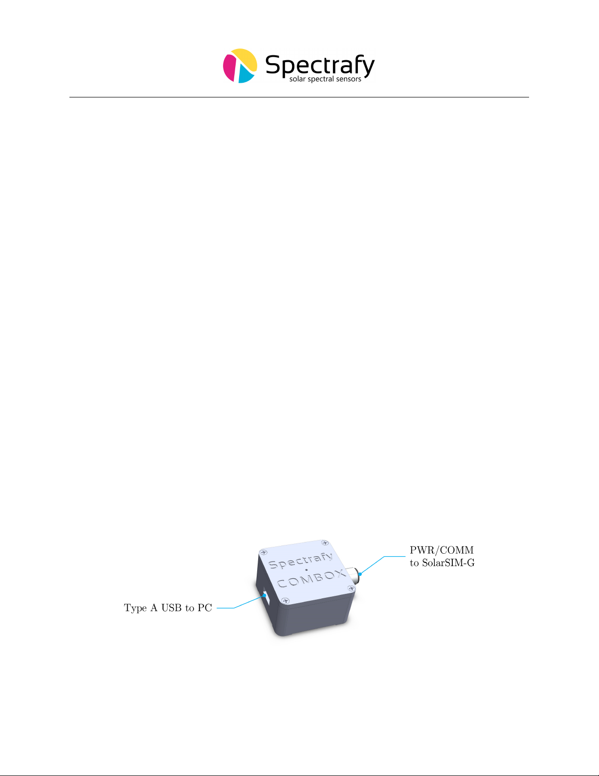
Option 1 uses the SolarSIM Communication Box (COMBOX) - a seamless link between
a PC and the SolarSIM-G, as shown in Figure 4. A standard 6 ft USB cable is connected from
the COMBOX to a PC. On the other side, a 10 m RS-485 communication cable is connected
from the COMBOX to the SolarSIM-G. This option is ideal for test sites and locations where
one has the access to a personal computer (PC) or when quick, in-field spectral measurements
are necessary with a laptop.
Option 2 allows the user to interface with the SolarSIM-G via a serial-over-Ethernet
converter, provided there is Internet access. For this option the user must manually connect
the power and communication wires to the SolarSIM-G by following the wiring guide in
Section 4.2. This option is ideal for test sites and locations which have Internet access, but no
PC nearby. Both options 1 and 2 make use of the SolarSIM-G DAQ graphical user interface,
which must be installed on a Windows-based PC or a server, as explained in Section 5.
Option 3 uses a datalogger to acquire raw data from the SolarSIM-G. This raw data
must be specifically formatted by the user into a .csv file, which is then fed into the SolarSG
software to generate the complete SolarSIM-G data set, as further detailed to in Section 6.3.
This option is ideal for remote test sites and locations with existing datalogger systems.
Figure 4: The COMBOX interfaces the SolarSIM-G to a PC.
7
4.1 SolarSIM-G Communication Box
The COMBOX is the best option for stable communication between a PC and the SolarSIM-G.
Please follow these steps to install the COMBOX:
1. Connect one end of the communication cable to the SolarSIM-G.
2. Connect the other end to the COMBOX.
3. Connect one end of a male-to-male USB cable to the COMBOX.
4. Connect the other end of a male-to-male USB cable to a PC. A blue LED on the
top of the COMBOX indicates power to the SolarSIM-G.
5. Wait for the PC to install the FTDI drivers, which may take a few minutes.
6. Once the FTDI drivers are installed, restart the PC.
4.2 Serial-over-Ethernet converter
For remote test site applications the SolarSIM-G can be connected to a networked PC via a
suitable serial-over-Ethernet (SOE) converter - such as the ICP DAS I-7188-E21. The user
must connect the SolarSIM-G communication cable wires as per Table 1. More specifically,
the D+ and D−lines, brown and black wires, respectively, must be connected to the corre-
sponding terminal block inputs on the SOE device, while the blue and white wires - to the
positive and common ground sides of the 12 VDC power supply, respectively. The SOE con-
verter and the power supply must have a common ground. Note, supplying the SolarSIM-G
with the voltage higher than
12 VDC
will damage the SolarSIM-G electronics.
The network must assign a static IP address to the SOE converter. Afterwards, a
virtual communication link can be established via the VxComm software2. The latter must
be configured as per Figures 5 and 6. Once properly configured, the VxComm software
creates a virtual serial port on the networked PC, which the SolarSIM-G DAQ application
uses to communicate to the SolarSIM-G.
1https://www.icpdas-usa.com/i_7188e2.html
2http://ftp.icpdas.com/pub/cd/8000cd/napdos/driver/vxcomm_driver/windows/
Table 1: Wiring guide for the SolarSIM-G.
Colour Label Function
Blue Vin Input voltage (+12 VDC)
White GND Common ground
Black D−Negative RS-485 input
Brown D+Positive RS-485 input
∗12 VDC only
8

Figure 5: Server configuration for VxComm software. Note, the SolarSIM-G supports only
the ASCII RS-485 communication mode.
Figure 6: Port configuration for VxComm software. Note, the SolarSIM-G supports only
the ASCII RS-485 communication mode.
9
4.3 Datalogger
The connectivity with a datalogger is similar to the SolarSIM-G’s integration with the SOE
converter. The SolarSIM-G communication cable is connected to the corresponding datalog-
ger inputs as per Section 4.2. The datalogger must have a spare RS-485 port.
5 SolarSIM-G DAQ Application
The SolarSIM-G DAQ application provides the user with the real-time status of the instru-
ment, performs the data acquisition and storage of data, and displays daily data plots for
various parameters. The SolarSIM-G DAQ software communicates via a serial port and thus
can be used with either a COMBOX or a SOE converter. This section will go over the soft-
ware installation, the program settings, and the general know-how for using the SolarSIM-G
DAQ.
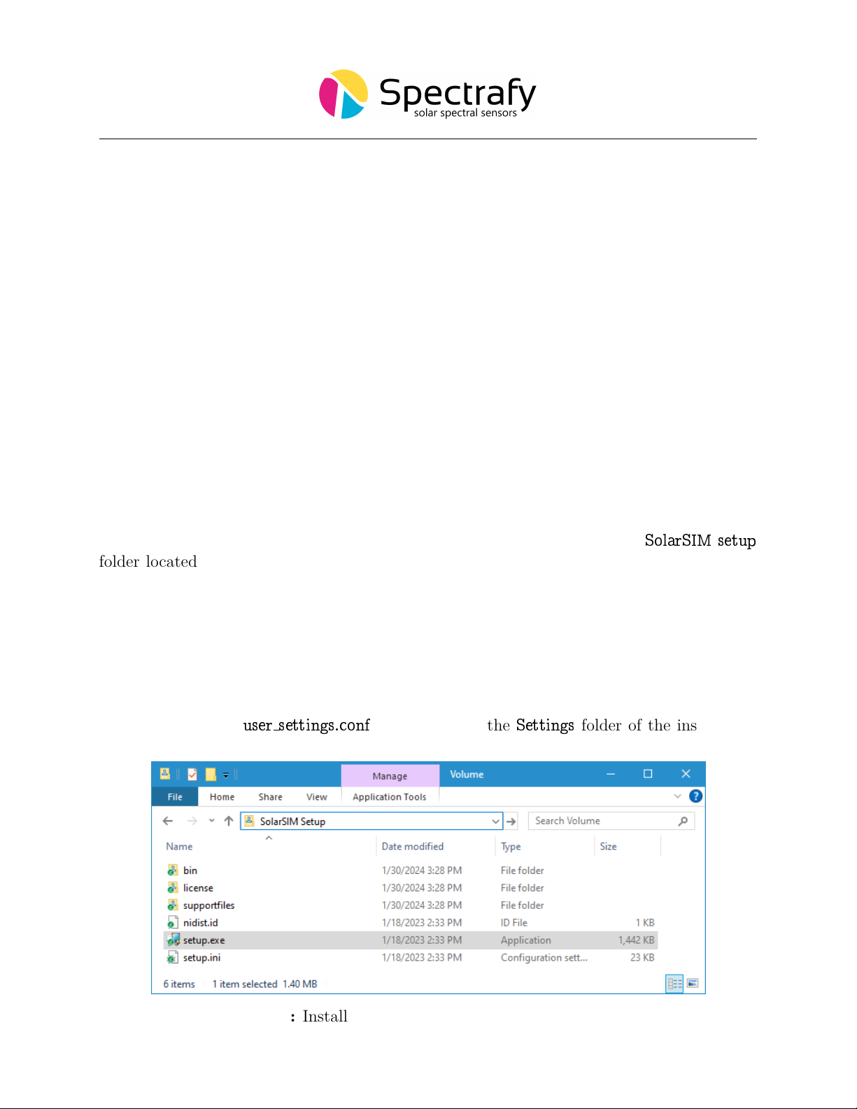
5.1 Software installation
The software installation is performed by executing the setup.exe inside the
SolarSIM setup
folder located on the provided USB key, as shown in Figure 7. The user should follow the
installation instructions as prompted by the software.
5.2 Software settings
Once the SolarSIM-G software is installed, the user must define the location-specific geo-
graphic settings for the SolarSIM-G to work properly. This process can be accomplished
in two ways. The first option is for the user to change the values for altitude, longitude,
and latitude in the
user settings.conf
file, located in the
Settings
folder of the installation
Figure 7: Installation of the SolarSIM-G DAQ software
10

Figure 8: Adjustment of the SolarSIM-G user settings.
directory, as shown in Figure 8. The second option is to modify these parameters when auto-
matically prompted by the software, as will be explained in Section 5.3. The modifications of
the remaining parameters is optional. If
Auto mode
is ON, upon launching, the application
does not interact with the user and begins the data collection automatically. The
DAQ timer
sets the data acquisition resolution for the entire SolarSIM-G data set, while the sampling
rate determines how often to poll the measurements over the duration of the DAQ rate. If
it is desired to have a separate data rate for the spectral data, the user can turn ON the
Custom spectrum timer
and change the spectral data acquisition to a desired rate via the
Spectrum timer
. Finally, if the user desires to save the raw data from the instrument, the
Raw data ouput
setting should be set to ON. Please refer to Table 2 for the summary of the
user settings.
11
Table 2: SolarSIM-G DAQ program settings.
Setting Value range Units
Altitude 0.0 to 9000.0 metres
Longitude 0.00 to 180.00∗degrees
Latitude 0.00 to 90.00∗ ∗ degrees
Auto mode 0 or 1 OFF or ON
DAQ rate 1 to 3600 seconds
Sampling rate 1 to 3600 seconds
Custom spectrum timer 0 or 1 OFF or ON
Spectrum timer 1 to 3600 seconds
Raw data output 0 or 1 OFF or ON
∗longitude is negative for western hemisphere
∗ ∗ latitude is negative for southern hemisphere
5.3 Using the software
The SolarSIM-G software is launched by double-clicking the
SolarSIM-G DAQ SNxxxx.exe
in the installation directory, where
xxxx
is a 4-digit serial number of your SolarSIM-G. The
application runs automatically in the
Administrator mode
, as it is a prerequisite to save the
data in the
Program les
directory. Once launched, the program automatically searches for
the SolarSIM-G calibration file. If the SolarSIM-G DAQ detects multiple calibration files,
the application will prompt the user to select the serial number of the desired SolarSIM-G,
as shown in Figure 10.
The SolarSIM-G DAQ software then searches for the serial port to which the SolarSIM-G
is connected. If the SolarSIM-G is not detected, the program displays the message as shown
in Figure 11 and exits. In this case, please ensure that your PC detects the serial port by
viewing the available serial or COM ports in the
Device manager
. If similar problem arises
with the SOE converter, please double-check the setup procedure as specified in Section 4.2.
Once the SolarSIM-G’s serial port is found, the SolarSIM-G DAQ prompts the user to
verify and/or change the geographic settings, which include altitude, longitude and latitude,
as shown in Figure 12. If these parameters are incorrect, the user can change them by
modifying the appropriate values in the pop-up window. When ready, press
Apply
, and
the program will save these settings permanently by writing them to the
user settings.conf
file. Please note that the latitude and longitude must be negative for southern and western
hemispheres, respectively.
The SolarSIM-G DAQ software is depicted in Figure 13. The fully licensed version of
the software displays the real-time global spectral irradiance, the daily plots of the various ir-
radiances (e.g. broadband, UV-A, UV-B, UV-E, photosynthetically active radiation or PAR),
spectral correction factors for up to nine user-defined PV panel spectral responses, ambient
temperature and pressure, internal temperature and humidity, individual SolarSIM-G chan-
12

Figure 9: Browsing to the calibration file.
Figure 10: Selecting multiple calibration files.
Figure 11: Failing to detect the SolarSIM-G.
Figure 12: Changing and verifying geographic settings.
13
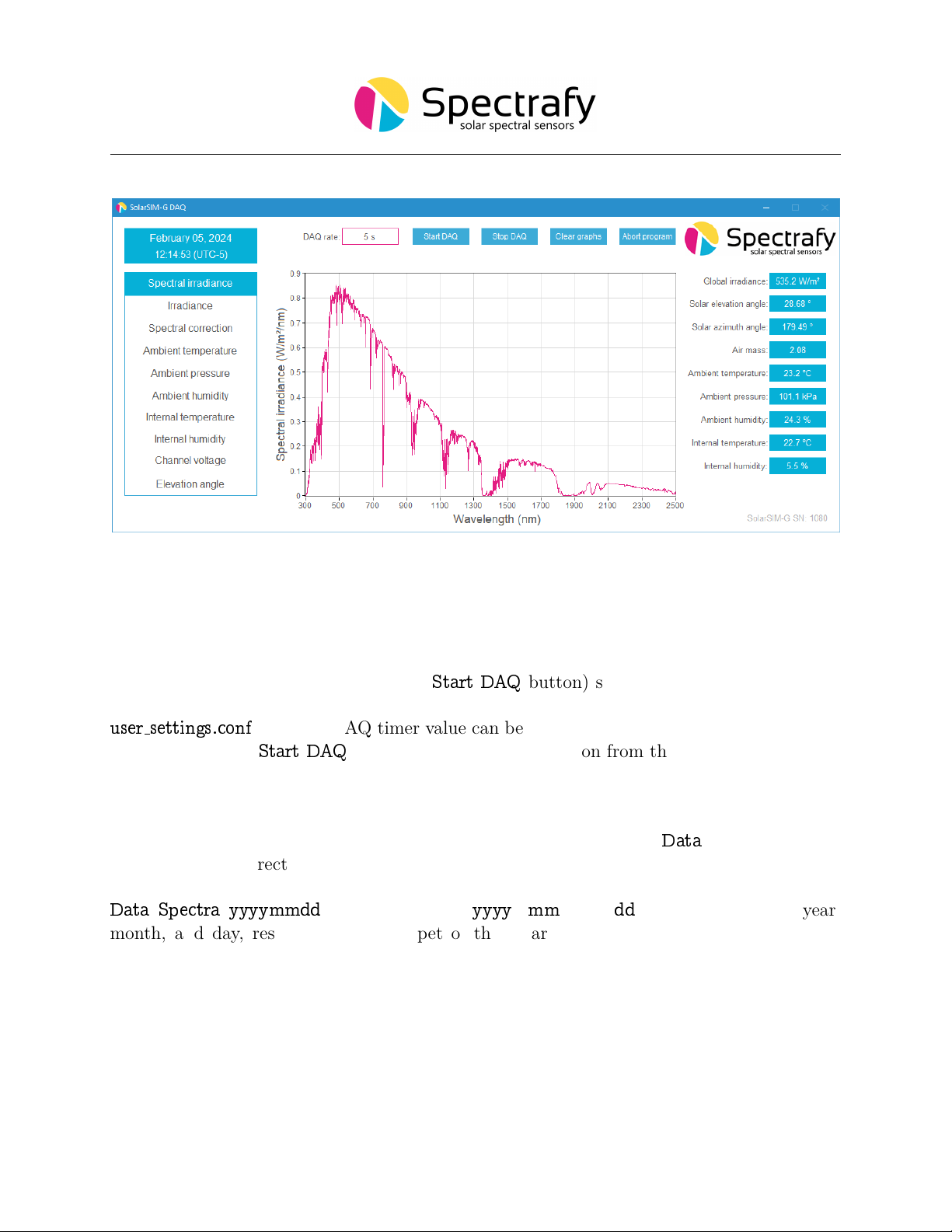
Figure 13: SolarSIM-G DAQ application
nel voltages, and the elevation angle. Data for plots, other than the ambient temperature
and pressure, and internal temperature and humidity, is recorded between the sunrise and
the sunset.
The desired DAQ rate (left of the
Start DAQ
button) should be set before beginning
the data acquisition. It has a default value of 5 s, but it can be changed by modifying the
user settings.conf
file. The DAQ timer value can be set between 1 s and 3600 s. Finally, the
user can press the
Start DAQ
button to begin data collection from the SolarSIM-G.
5.4 Data type and storage
The SolarSIM-G DAQ stores the SolarSIM-G’s processed data in the
Data
folder, located in
the installation directory. The software outputs two processed data files types: the so-
lar spectral files and the daily summary data files. The spectral data is stored in the
Data
\
Spectra
\
yyyymmdd
directory, where
yyyy
,
mm
, and
dd
correspond to the year,
month, and day, respectively. A snippet of the SolarSIM-G spectrum file is presented in
Figure 14. As shown, the wavelength column is not included in order to minimize the file
size. Rather the 3721 values of the spectral irradiance in units of W/m2/nm are presented in
a single column format. The value in row 2 corresponds to the spectral irradiance at 280 nm,
while the value in row 3722 corresponds to the spectral irradiance at 4000 nm.
14

The daily summary data files are stored in the
Data
folder. A snippet of the SolarSIM-G
data file is shown in Figure 15. It contains the values for the elevation and azimuth angles, the
ambient temperature, the ambient pressure, the ambient humidity, the internal temperature,
the internal humidity, the broadband global irradiance, PAR, UV-A, UV-B, UV-E, and nine
spectral correction factors.
Additionally, if the user has enabled the
Raw data output
setting, the software saves
raw daily data files in the
Raw data
folder. See Section 6.3 for more information on the raw
data files.
5.5 Data collection size
At 5 s DAQ rate and assuming 8 hr of sunshine, the daily summary file size will be ∼1 MB
or ∼170 bytes per timestamp. The spectral file size is ∼37 KB per measurement, so for
a 8 hr of sunshine day at 5 s DAQ rate, the daily spectral data size will be ∼213 MB.
The user is advised to use the
Custom spectrum timer
and
Spectrum timer
options in the
user settings.conf
file to reduce the daily spectral data set size as desired.
Figure 14: SolarSIM-G spectrum data file snippet.
Figure 15: SolarSIM-G daily summary file snippet.
15

5.6 Changing default language for non-Unicode characters
For users of computers with non-Latin based languages, such as Mandarin, the SolarSIM-G
DAQ may improperly display non-Unicode characters. To solve this problem, the user must
change the default language for non-Unicode programs to English. To do so, first locate the
Clock, Language, and Region
settings in the
Control Panel
, then click on
Region
settings,
as show in Figure 16. Then navigate to the
Administrative
tab and select
Change system
locale...
, as demonstrated in Figure 17. Lastly, change the language to
English
from the drop
down menu, as shown in Figure 18, and press
OK
.
Figure 16: Clock, Language, and Region settings in the Control Panel.
Figure 17: Changing the system locale in the Administrative tab of the Region settings.
16
Table of contents
Other Spectrafy Measuring Instrument manuals

Popular Measuring Instrument manuals by other brands

Growatt
Growatt ShineWiFi-S Quick Installation Guideline

CHAMELEON
CHAMELEON IHD6-CAD-PPMID manual

Klein Tools
Klein Tools ET140 instruction manual

ICS Schneider Messtechnik
ICS Schneider Messtechnik GA35 operating instructions

Bender
Bender ISOMETER isoNAV685-D manual

Geokon
Geokon 4200 Series instruction manual


