Spectrafy SolarSIM-GPV User manual
User Manual:
Solar Spectral Irradiance Meter
SolarSIM-GPV
©Spectrafy, 2022

User information
Spectrafy Inc. strongly recommends reading this instruction manual prior to installation and
operation of your global Solar Spectral Irradiance Meter (SolarSIM-GPV).
If you have any comments about this manual or our products, please send them to:
Spectrafy Inc. Inc.
4 Florence St, Suite 204
Ottawa, Ontario, Canada
K2P 0W7
Tel: 1-613-237-2020
www.spectrafy.com
Spectrafy Inc. reserves the right to make modifications to the user manual without prior
notice.
Warranty and liability
Spectrafy Inc. guarantees that the Solar Spectral Irradiance Meter (SolarSIM-GPV) has been
thoroughly tested to ensure that it meets all of the stated specifications. A two year warranty
is provided from date of invoice, subject to correct installation and operation. Spectrafy Inc.
accepts no liability for any loss or damages arising from improper usage of this product.
i

Contents
Introduction 1
1 Main components 2
1.1 Glassdome .................................... 3
1.2 Enclosure ..................................... 3
1.3 Bandpassfilters.................................. 3
1.4 Bubblelevel.................................... 3
1.5 Connector..................................... 3
1.6 Backplate ..................................... 3
2 Installation 4
2.1 Contentsofdelivery................................ 4
2.2 Mechanicalinstallation.............................. 4
3 Maintenance 5
3.1 Cleaning...................................... 5
3.2 Alignment..................................... 5
3.3 Desiccant ..................................... 5
3.4 Recalibration ................................... 5
4 Connectivity 7
5 Data outputs 8
5.1 Dataoutputs ................................... 9
5.2 User defined spectral response curves . . . . . . . . . . . . . . . . . . . . . . 10
6 Support 10
ii

List of Figures
1 SolarSIM-GPV components and main dimensions. . . . . . . . . . . . . . . . 2
2 Assembled SolarSIM-GPV on the mounting plate. . . . . . . . . . . . . . . . 6
3 Dimensional drawing of a mounting plate. . . . . . . . . . . . . . . . . . . . 6
4 Main dimensions of the iSG. . . . . . . . . . . . . . . . . . . . . . . . . . . . 7
List of Tables
1 SolarSIM-GPV data outputs . . . . . . . . . . . . . . . . . . . . . . . . . . . 9
iii

Introduction
Dear customer, thank you for purchasing the Solar Spectral Irradiance Meter (SolarSIM-GPV)
from Spectrafy. Please become familiar with this instruction manual for a full understanding
of the use of your SolarSIM-GPV.
The SolarSIM-GPV is designed to be a cost-effective tool for accurately determining spec-
trally corrected global horizontal/tilted irradiance (GHI/GTI) for use in solar resource mea-
surement campaigns and PV plant performance monitoring. The instrument uses silicon
photodiodes, integrated with hard-coated bandpass filters to measure the solar spectral ir-
radiance in nine narrow wavelength bands. The SolarSIM-GPV’s proprietary software uses
these measurements to resolve the global horizontal/tilted solar spectral irradiance and sub-
sequently, the global horizontal/tilted irradiance and PV spectral correction factors for up
to nine difference PV panels. This SolarSIM-GPV’s data can be used within any standard
PV modelling software to quantify and account for the effects of solar spectral variation on
PV performance.
If you have any questions, please feel free to contact a Spectrafy representative or e-mail
1


1.1 Glass dome
The glass dome prevents the ingress of moisture and debris.
1.2 Enclosure
The anodized aluminum enclosure secures SolarSIM-GPV components in place, while pro-
viding robust protection from the environment.
1.3 Bandpass filters
Nine bandpass filters transmit a narrow band of spectral irradiance to the detectors.
1.4 Bubble level
The bubble level ensures the SolarSIM-GPV is leveled when measuring the irradiance in
global horizontal orientation.
1.5 Connector
The connector provides power and communication to the SolarSIM-GPV electronics.
1.6 Backplate
The anodized aluminum backplate seals the back of the enclosure with four screws.
3

2 Installation
2.1 Contents of delivery
A typical SolarSIM-GPV delivery contains:
•1×SolarSIM-GPV,
•1×communication cable,
•1×SolarSIM-G COMBOX (optional),
•1×MP-G mounting plate (optional),
•3×mounting screws and springs, and
•a USB key loaded with the SolarSIM-GPV user manual and calibration certificate.
Please check the contents of your package and note if any damages have occurred during
shipment. A claim should be filed with the shipment carrier should this be the case. Addi-
tionally, please contact a Spectrafy representative to facilitate the repair or replacement of
the instrument and/or its accessories.
2.2 Mechanical installation
Installation of the SolarSIM-GPV consists of fastening it to a mounting plate using three M4
screws and springs, as demonstrated in Figure 2. The mounting plate can then be mounted
to a pole or table as required. The mounting plate is 7.3 mm thick and has three slots
with a 132 mm diameter that are 4.5 mm wide for external fastening, as shown in Figure 3.
The screws/bolts for external mounting are not provided. The procedure for mechanical
installation (in horizontal orientation) is described as follows:
1. Place the SolarSIM-GPV on the mounting plate as per Figure 3.
2. Place the springs under the SolarSIM-GPV so that they roughly align with the
mounting holes on the SolarSIM-GPV.
3. Insert the M4 mounting screws through the SolarSIM-GPV mounting holes and
springs. Then thread the screws into the mounting plate for several revolutions.
4. Adjust the mounting screws until the bubble level is centered within the circle.
5. The SolarSIM-GPV mounting plate can then be mounted to a table or tube/pipe
with screws or u-bolts as required.
6. Once mounted, adjust the SolarSIM-GPV’s mounting screws/springs until the
bubble level is centered within the circle.
4

Note that the SolarSIM-GPV can also be deployed in fixed-tilt and plane-of-array applica-
tions, in which cases the springs and levelling process are not necessary.
3 Maintenance
The SolarSIM-GPV requires very little maintenance. The primary concern is to ensure that
the glass dome of the SolarSIM-GPV is clean at all times, as the accumulation of dirt can
lead to underreported and inaccurate data. Spectrafy’s GV-1 ventilator can aid in this.
Furthermore, the levelling of the SolarSIM-GPV should be checked periodically.
3.1 Cleaning
As a general rule, we recommend cleaning the SolarSIM-GPV’s front glass with a dry, non-
abrasive cloth once per week, in order to maintain optimal performance. This frequency can
be altered depending on your local climatic conditions.
3.2 Alignment
With each cleaning, it is also advised to check the levelling of the instrument using the bubble
level. If the bubble is not centered within the circle, adjust the mounting screws as needed
to re-level the SolarSIM-GPV.
3.3 Desiccant
The desiccant is used to maintain an appropriate humidity level within the SolarSIM-GPV.
The internal humidity of the device is reported as one of the sensor’s data outputs and can
therefore be monitored over time. The lifetime of the desiccant is expected to exceed two
years, although it may vary based on local climatic conditions. The desiccant can be replaced
as part of the SolarSIM-GPV’s re-calibration procedure.
3.4 Recalibration
We recommend that the SolarSIM-GPV is returned to Spectrafy for recalibration every 1-2 years
in order to maintain the SolarSIM-GPV’s specified measurement accuracy.
5
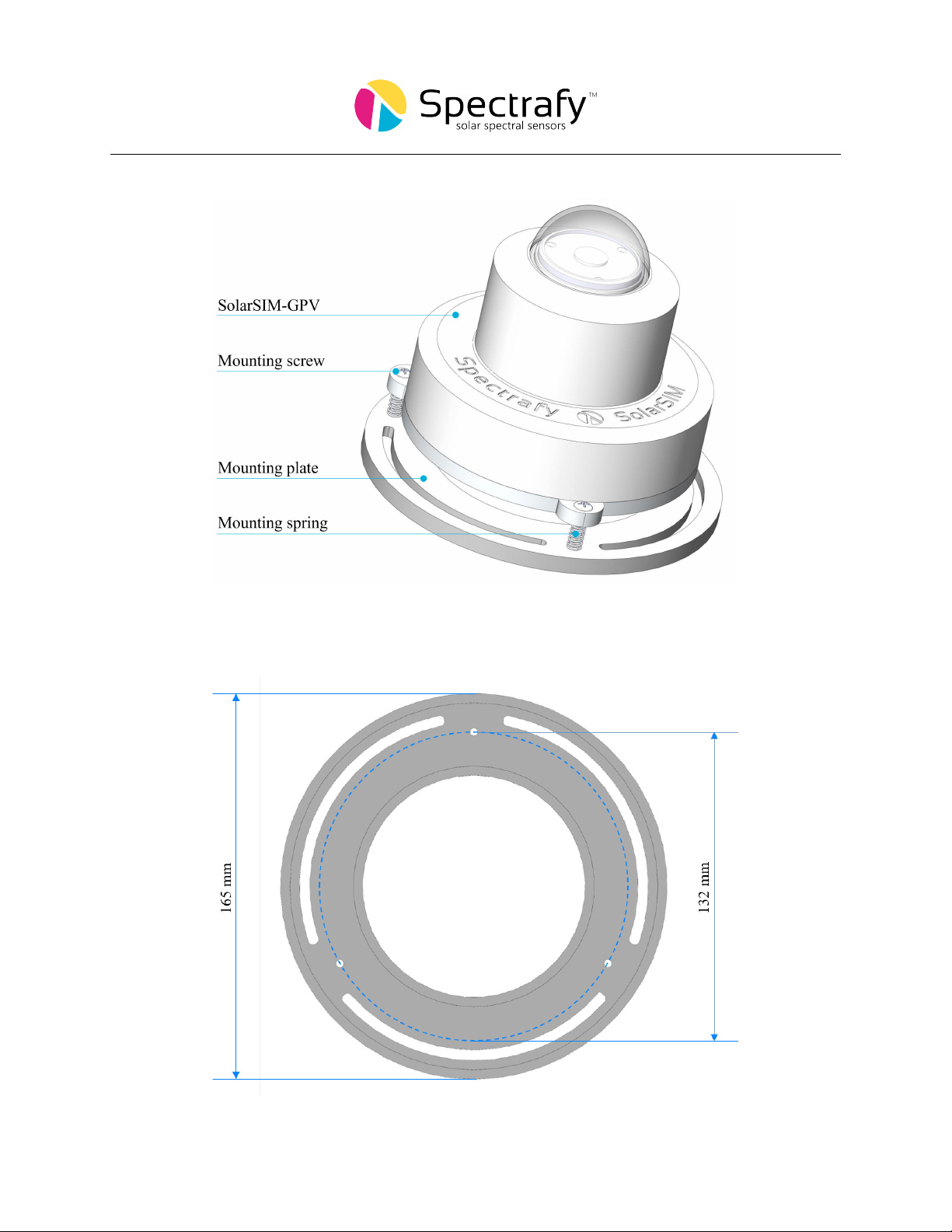
Figure 2: Assembled SolarSIM-GPV on the mounting plate.
Figure 3: Dimensional drawing of the mounting plate. Note the three mounting holes are
M4 thread.
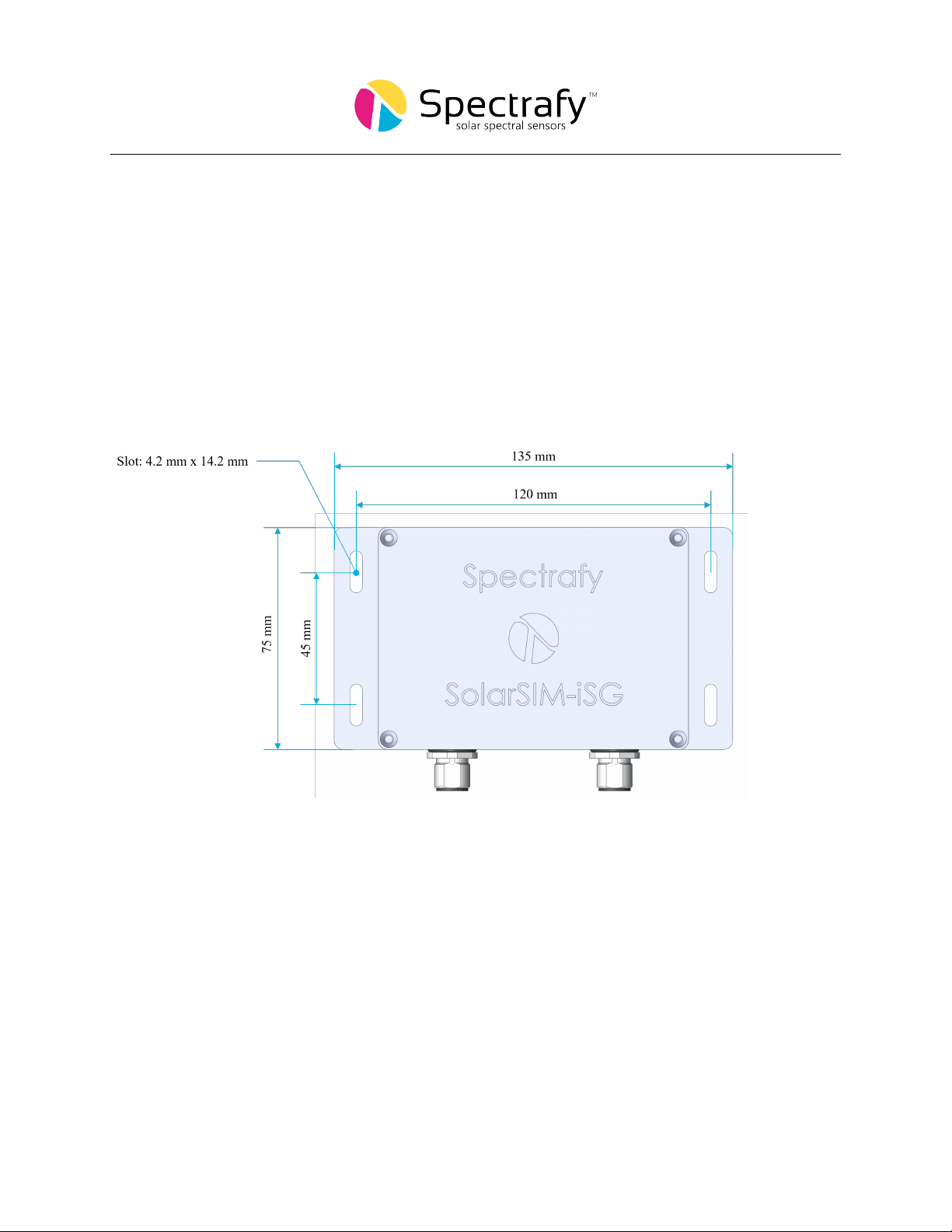
4 Connectivity
The SolarSIM-GPV uses the iSG Integrated Spectrum Generator add-on to automatically
process it’s raw data and output global solar irradiance (GHI/GTI/POAI) and PV spec-
tral correction factors directly to a datalogger over RS-485 modbus. The iSG consists of a
150x100x50mm, IP66 rated aluminium enclosure that can be deployed in open air, or within
a datalogger enclosure, where it mounts by standard DIN rail. For more information re-
garding the operation and integration of the iSG, please see our Application note entitled:
SolarSIM-iSG Datalogger Integration.
Figure 4: Main dimensions of the iSG.
7

5 Data outputs
The SolarSIM-GPV uses Spectrafy’s innovative multispectral measurement approach to ac-
curately resolve the global solar spectrum over the 280-4000nm wavelength range. From
this spectral irradiance data, the SolarSIM-GPV outputs the global irradiance (calculated
from the wavelength integral of the spectral irradiance) and PV spectral correction factors
(SCF) for up to nine different PV panels. The spectral correction factors are automatically
calculated using an equation derived from IEC 60904-7:2019 ”Photovoltaic devices - Part
7: Computation of the spectral mismatch correction for the measurement of photovoltaic
devices”:
SCF =
R4000
280 EAM1.5Gdλ ×R4000
280 EM·SRPVdλ
R4000
280 EMdλ ×R4000
280 EAM1.5G ·SRPVdλ
Where:
SCF is the spectral correction factor.
EAM1.5G is the AM1.5G (ASTM G-173) reference spectrum.
EMis the measured spectral irradiance resolved by the SolarSIM-GPV.
SRPV is the spectral response of the PV panel of interest.
Spectral correction factors provide simple, intuitive datapoints that quantify the effect
of local spectral conditions on the performance of the PV panel of interest. An SCF greater
than one indicates that the local spectral condiitons are providing a boost to the PV panel
performance as compared to reference spectral conditions. Conversely, a SCF less than one
indicates the local spectral conditions are reducing the PV panel performance as compared
to reference spectral conditions.
Spectrally corrected global irradiance can be obtained from the SolarSIM-GPV’s global
irradaince and SCF data outputs as follows:
GIspec.corr. =GI ×SCF
Spectrally corrected irradiance data can then be used, much like uncorrected GHI would be,
within any standard PV performance modelling software (eg. PVSyst, Plant Predict). Please
note that when using spectrally corrected irradiance data, any spectral correction algorithms
within the PV modelling software should be turned off.
8

5.1 Data outputs
The SolarSIM-GPV+iSG, outputs data as detailed in Table 1 below.
Table 1: SolarSIM-GPV data outputs
Parameter Name Units Notes
TimeStamp Local timestamp N/A
G Irradiance Global irradiance W/m2GHI/GTI (Class A)
G SCF 1 Spectral corr. factor 1 N/A First Solar S3+
G SCF 2 Spectral corr. factor 2 N/A First Solar S4v1
G SCF 3 Spectral corr. factor 3 N/A First Solar S4v2
G SCF 4 Spectral corr. factor 4 N/A First Solar S6
G SCF 5 Spectral corr. factor 5 N/A PERC Mono Si
G SCF 6 Spectral corr. factor 6 N/A PERC Poly Si
G SCF 7 Spectral corr. factor 7 N/A Poly Si
G SCF 8 Spectral corr. factor 8 N/A CIGS
G SCF 9 Spectral corr. factor 9 N/A a-Si panel
G AMBIENT PRESSURE Ambient pressure kPa
G AMBIENT TEMP Ambient temperature ◦C
G AMBIENT HUMIDITY Ambient humidity %
G INTERNAL TEMP Internal temperature ◦C
G INTERNAL HUMIDITY Internal humidity %
G VOLTAGE CH1 Channel 1 voltage mV
G VOLTAGE CH2 Channel 2 voltage mV
G VOLTAGE CH3 Channel 3 voltage mV
G VOLTAGE CH4 Channel 4 voltage mV
G VOLTAGE CH5 Channel 5 voltage mV
G VOLTAGE CH6 Channel 6 voltage mV
G VOLTAGE CH7 Channel 7 voltage mV
G VOLTAGE CH8 Channel 8 voltage mV
G VOLTAGE CH9 Channel 9 voltage mV
9

5.2 User defined spectral response curves
The SolarSIM-GPV comes with nine default spectral response (SR) curves as detailed in Ta-
ble 5. The SolarSIM-GPV can also be used with user-defined SR curves. If you would like to
use alternative SR curves, please contact us at info@spectrafy.com before your SolarSIM-GPV
unit is shipped, so that your SR curves can be incorporated into the software. User-defined
SR curves need to be formatted to 1nm resolution and span the wavelength range from 280-
4000nm.
6 Support
Please contact us at info@spectrafy.com if you have any questions about the implementation
or operation of the SolarSIM-GPV.
10
Table of contents
Other Spectrafy Measuring Instrument manuals


