SpectraPure MC-RODI-UHE-400 User manual

MaxCap-400 Ultra-High Efficiency RO/DI
(MC-RODI-UHE-400)
INSTRUCTIONS
WARNING
Please read carefully before proceeding with installation. Failure to follow any
attached instructions or operating parameter may lead to the product’s failure and
possible damage to property.
REV. 02-17-2010

SpectraPure
SpectraPure®Inc.
480.894.5437 Call us toll-free 1.800.685.2783
2167 East Fifth St, Tempe, Arizona 85281
®2
TABLE OF CONTENTS
Operational Specifications
Contents of Drinking Water Systems ....................................................................................................................................... 3
Operation Description (how the system functions). . . . . . . . . . . . . . . . . . . . . . . . . . . . . . . . . . . . . . . . . . . . . . . . . . . . . . . . . . . . . . . . . . . . . . . . . . . . . . . . . . . . . . . . . . . . . . . . . . . . . . . . . . . . . 4
Preparation
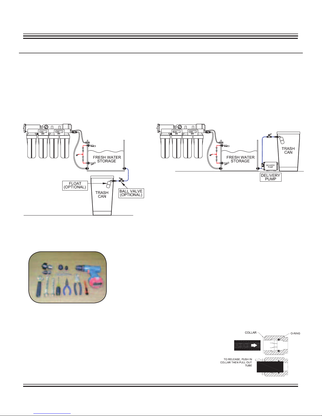
Choosing the best Mounting Location.................................................................................................................................... 5
Tools recommended for installation. . . . . . . . . . . . . . . . . . . . . . . . . . . . . . . . . . . . . . . . . . . . . . . . . . . . . . . . . . . . . . . . . . . . . . . . . . . . . . . . . . . . . . . . . . . . . . . . . . . . . . . . . . . . . . . . . . . . . . . . . . . . . . ............ 5
Introduction to push fittings . . . . .. . . . .. . . .. . . . .. . . .. . . . .. . . .. . . . .. . . .. . . . .. . . .. . . . . .. . . .. . . . .. . . .. . . . .. . . .. . . . .. . . .. . . . .. . . .. . . . .. . . . .. . . . .. . . .. . . . .. . . .. . .......................... 5
Getting to know your system ..... . . . . . . ......................... . . . . . .................... . . . . . ......................... . . . . . . ................... . . . . . . ............................ 6
Set-Up Procedures. . . . . . . . . . . . . . . . . . . . . . . . . . . . . . . . . . . . . . . . . . . . . . . . . . . . . . . . . . . . . . . . . . . . . . . . . . . . . . . . . . . . . . . . . . . . . . . . . . . . . . . . . . . . . . . . . . . . . . . . . . . . . . .............................................. 7
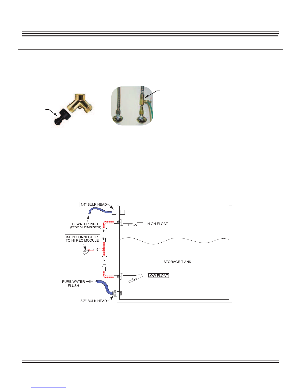
Installation of floats for the Pure Water Flush Cycle Tank. . . . . . . . . . . . . . . . . . . . . . . . . . . . . . . . . . . . . . . . . . . . . . . . . . . . . . . . . . . . . . . . . . . . . . . . . . . . . . . . . . . . . . . . . . . . . . . . . . 7
Pressure adjustment with regulator . . . . . . . . . . . . . . . . . . . . .. . . . . . . . .. . . . . . . . .. . . . . . . . .. . . . . . . . . . . .. . . . . . . . .. . . . . . . . .. . . . . . . . .. . . . . . . . .. . . . . . . . . . .. . . . . . . . . .. . . . . . . . . ............ 8
Adjusting Concentrate to Purified Water ratio ...................................................................................................................... 8
Re-installing DI resin cartridges. . . . . . . . . . . . . . . . . . . . . . . . . . . . . . . . . . . . . . . . . . . . . . . . . . . . . . . . . . . . . . . . . . . . . . . . . . . . . . . . . . . . . . . . . . . . . . . . . . . . . . . . . . . . . . . . . . . . . . . . . . . . . . ..................... 8
Connecting Bulk Head fittings .................................................................................................................................................... 9
Final Connection............................................................................................................................................................................. 1 0
Maintenance Regimen
Metering & Diagnostics ................................................... ......................... . . . . . . .............................................................................. 1 1
Shelf life for filters. . . . . . . . . . . . . . . . . . . . . . . . . . . . . . . . . . . . . . . . . . . . . . . . . . . . . . . . . . . . . . . . . . . . . . . . . . . . . . . . . . . . . . . . . . . . . . . . . . . . . . . . . . . . . . . . . . . . . . . . . . . . . . .............................................. 1 1
Sediment Pre-Filter replacement. . . . . . . . . . . . . . . . . . . . . . . . . . . . . . . . . . . . . . . . . . . . . . . . . . . . . . . . . . . . . . . . . . . . . . . . . . . . . . . . . . . . . . . . . . . . . . . . . . . . . . . . . . . . . . . . . . . . . . . . . . . . . . .................. 1 1
Carbon Block Pre-Filter replacement. . . . . . . . . . . . . . . . . . . . . . . . . . . . . . . . . . . . . . . . . . . . . . . . . . . . . . . . . . . . . . . . . . . . . . . . . . . . . . . . . . . . . . . . . . . . . . . . . . . . . . . . . . . . . . . . . . . . . . . . . . . . . . .......... 1 2
Reverse Osmosis Diagnostics. . . . . . . . . . . . . . . . . . . . . . . . . . . . . . . . . . . . . . . . . . . . . . . . . . . . . . . . . . . . . . . . . . . . . . . . . . . . . . . . . . . . . . . . . . . . . . . . . . . . . . . . . . . . . . . . . . . . . . . . . . . . . . ........................ 1 2
Reverse Osmosis Membrane Performance Testing ............................................................................................................. 1 3
Reverse Osmosis Membrane replacement . . . . . . . . . .. . . . .. . . . .. . . .. . . . .. . . . .. . . . .. . . .. . . . .. . . . . .. . . .. . . . .. . . . .. . . . .. . . .. . . . .. . . . .. . . . .. . . .. . . . .. . . . . .. . . . .. . . .. . . . .. . . . 1 4
Tips for long membrane life .. . ..... . ..... . .... . ..... . ..... . .... . ..... . .... . .... . ..... . .... . ..... . .... . ..... . ..... . .... . ..... . .... ..... . ..... . .... . ..... . ........................... 1 4
De-Ionization Cartridge maintenance and replacement. . . . . . . . . . . . . . . . . . . . . . . . . . . . . . . . . . . . . . . . . . . . . . . . . . . . . . . . . . . . . . . . . . . . . . . . . . . . . . . . . . . . . . . . . . . . . . . . . . . 1 5
Troubleshooting Guide................................................................................................................................................................ 1 6
Warranty Information ................................................................................................................................................................... 1 7
Replacement Parts List .................................................................................................................................................................. 1 8
Copyright © 2009 by SpectraPure Inc.
ALL RIGHTS RESERVED
No part of this publication may be reproduced, stored in a retrieval system, or transmitted in any
form or by any means, electronic, mechanical, photocopying, recording or otherwise without
the prior written permission of SpectraPure Inc.
Thank You for your purchase of a
SpectraPure® System. With proper installation and maintenance, this system will
provide you with high quality water for years to come. All SpectraPure® products are rigorously tested by us for
safety and reliability. If you have any questions or concerns, please contact our customer service department at
1.800.685.2783 or refer to our online troubleshooting at www.spectrapure.com.

SpectraPure®Inc.
480.894.5437 Call us toll-free 1.800.685.2783
2167 East Fifth St, Tempe, Arizona 85281
SpectraPure
®3
RO Feed water requirements
Tap Water Pressure: 30 PSI.
pH Range: 3-11.
Max. Temperature: 100°F (38°C).
Max. Feed Turbidity: 1.0 NTU.
Max. Silt Density Index: 5.0 (based on 15 min. test time).
Maximum Chlorine: <0.1 ppm
Maximum TDS: 2000 ppm.
Maximum Hardness: 10grains (170 ppm as CaCO3).
Maximum Iron: <0.1 ppm.
Maximum Manganese: <0.1 ppm
Maximum Hydrogen Sulfide: 0ppm.
Langlier Saturation Index (LSI): must be negative.
OPERATIONAL SPECIFICATIONS
NOTE: MOST MUNICIPAL WATER SUPPLIES MEET THE ABOVE REQUIREMENTS. IF WELL WATER IS USED, PLEASE
MAKE SURE THAT YOU OBTAIN A WATER TEST BEFORE INSTALLATION.
UHE System Components
(1) 5-Stage System
- (1) Membrane (300 GPD)
- (1) 20”, 0.2 Micron Zeta-Zorb Sediment Filter
- (1) 20”, 0.5 Micron Carbon Block
- (1) 20”, MaxCap DI Cartridge
- (1) 20”, Silica-Buster DI Cartridge
- (1) High Flow Re-Circ Pump
- (1) UHE Module
- (1) Pressure Regulator
CONTENTS OF UHE WATER SYSTEM
IF ANY OF THE ITEMS LISTED ABOVE ARE MISSING PLEASE CONTACT SPECTRAPURE PRIOR TO INSTALLATION.
ALL RETURNS WITHOUT RMA# WILL BE REFUSED. CLAIMS MUST BE WITHIN 10 DAYS FROM RECEIPT.
- (1) Liquid Filled Pressure Gauge
- (2) Dual Probe In-Line TDS Meters
(1) High & Low Float Switches (with 6ft extension cable &
transformer)
(1) Filter Wrench
(2) Bulk-Head Fittings
Solenoid Valve Controlled
Float Switches
3/8” BLACK LINE: Tap Water input
1/4” BLUE LINE: Product Water
3/8” YELLOW LINE: Waste Water
3/8” BLUE LINE: Pure Water Flush
UHE SYSTEM DIMENSIONS:
24 W x 34 H x 8 D
Sediment Filter
(SF-ZZ-0.2-ABS-20) Silica-Buster DI
Cartridge
(DI-MC-20)
Recirc Pump
TDS
METER #1 TDS
METER #2
300 GPD RO
MEMBRANE
Carbon Filter
(CF-0.5-20) MaxCap DI Cartridged
(DI-MC-20)

SpectraPure
SpectraPure®Inc.
480.894.5437 Call us toll-free 1.800.685.2783
2167 East Fifth St, Tempe, Arizona 85281
®4
1. First, the incoming feed water (3/8” Black line) is passed through a 0.2 micron Zeta-Zorb sediment pre-filter. This filter
isrequired to remove excess turbidity (particulate matter) that may cause the carbon block filter to plug.
2. The second stage of filtration is a 0.5 micron carbon block pre-filter. This filter removes organics and chlorine from the
feed water that can damage the membrane.
3. The third filtration stage of the system is a high rejection thin film composite (TFC) reverse osmosis membrane. It
removes over 98% of most inorganic salts, all micro-organisms and organics above 100 diatoms molecular weight.
4. The fourth and fifth stage filter are our
MAXCAP DI
™ cartridge followed by our SilicaBuster ™ cartridge.
These two cartridges remove the remaining silicates, phosphates, and nitrates left by an RO membrane.
High and Low Float Operation:
1.Floats are to be mounted horizontal when dry and float up when wet. (NOTE: Pressure switches could also be
used with pressure tanks. Please call for more details)
2.When the bottom float goes dry, the input solenoid (INSOL) is opened and one second later, the Re-Circ pump
(PUMP) turns on.
Flush Cycle (flush cycle consumes only a couple of quarts):
1.As the system is running, a periodic sequence of flushes is performed.
2.When the top float gets wet, or every 8 hours of uninterrupted operation, the flush cycle is initiated.
3.After the flush cycle, the system shuts down if the tank is full or pauses for an hour to let the pure water soak the
membrane before continuing.
OPERATION DESCRIPTION (how the system functions)
SpectraPure®Inc.assumes no responsibility for water damage due to leaks. It is
the user’s responsibility to determine that the system is leak-free.

SpectraPure®Inc.
480.894.5437 Call us toll-free 1.800.685.2783
2167 East Fifth St, Tempe, Arizona 85281
SpectraPure
®5
1. CHOOSING THE BEST MOUNTING LOCATION:
LIGHT SOURCE: Algae is more likely to thrive inside clear housings when exposed to ultraviolet light and other
sources like metal halide lighting. Avoid installing the unit in bright light or direct sunlight.
EXTREME TEMPERATURES: The unit MUST be kept out of areas that are subject to extreme temperatures like
freezing or temperatures greater than 100° F (38° C)
FRESH WATER RESERVOIR: Mount system in an area that will have enough room for a small trash can or reservoir.
This Fresh Water Reservoir is to be used for the Flush Cycle. (Reservoir needs to hold at least 10 gallons)
ELEVATION FOR SYSTEM: When mounting your UHE, make sure it is elevated above your fresh water reservoir:
2. TOOLS RECOMMENDED FOR INSTALLATION:
3. INTRODUCTION TO PUSH FITTINGS:
Push fittings are similar to a Chinese finger trap toy. In order to release its grip from tubing,..
-Firmly depress and hold the push-fitting collar down with your thumbnail.
-While the push-fitting collar is depressed, pull the tubing straight
out of the push-fitting. Once the tubing is removed, release the collar.
PREPARATION
GRAVITY DRAIN WATER FROM ELEVATED TANK TO TRASH
CAN FOR SALT MIXING OR TO SUMP
USE DELIVERY PUMP TO DELIVER WATER WHERE NEEDED
FOR SALT MIXING OR TO SUMP
- Adjustable Wrench
- Sharp Exacto Knife
- Open End Wrench(s)
- Electric Drill
-5/8” Drill bit
-13/16” Drill bit
- Phillips Screw Driver
- Trash Barrel or Reservoir
- Optional Ball Valve or
Float Valve. (as shown above)
- Optional Delivery Pump (as shown above)

SpectraPure
SpectraPure®Inc.
480.894.5437 Call us toll-free 1.800.685.2783
2167 East Fifth St, Tempe, Arizona 85281
®6
4. GETTING TO KNOW YOUR SYSTEM: I
f you are setting up this system for the first time, or replacing either DI cartridges,
it is very important that you rinse the MaxCap DI cartridge with the downstream DI removed. There is a large ionic
load present in a new MaxCap DI cartridge. Failure to flush this cartridge, will shorten the life of the down stream DI.
TOP VIEW
NOTE: When mounting your UHE,
make sure it is elevated above your
fresh water reservoir.

SpectraPure®Inc.
480.894.5437 Call us toll-free 1.800.685.2783
2167 East Fifth St, Tempe, Arizona 85281
SpectraPure
®7
FRESH WATER
STEP 1: Unscrew the third position housing (MaxCap DI) and the fourth position housing (Silica-Buster DI) from the system
and remove the DI Cartridges. Then, re-install the empty housings back onto the system.
STEP 2: Connect the 3/8” Black Line to the cold water line by using either the garden hose adapter, which is provided
with the system, or a Feed Water Adapter.
STEP 3: PURE WATER FLUSH CYCLE INSTALLATION USING THE HIGH & LOW FLOAT SWITCHES:
A.Install both the High and Low Floats onto a open container like a Rubber Maid
TM
trash can. The floats can be
mounted by drilling a 5/8” hole. (The High Float shuts down the system, while the Low Float turns the system
on).
B.Connect the floats to the “Y” adapter.
C.Attach the 3-pin connector on the float switches to the HI-REC MODULE.
NOTE: Floats are to be mounted horizontal when dry and float up when wet. In most instances we
recommend locating the low float approx. half way down your reservoir. DO NOT OVERTIGHTEN
when installing the floats.
STEP 4: For now, direct both the 3/8” blue (product) line and the yellow (waste) line to drain.
STEP 5: Open the cold water line, where the black line is connected to. Plug in the 24 V transformer to the UHE Module
and connect to power.
NOTE: Floats have to be installed in a FRESH WATER storage container.
NOTE: This system MUST be connected to the floats to operate the Flush Cycle. Failure to install
the pure water flush connection for this unit will void any warranty.
SET-UP PROCEDURES
Garden Hose
Adapter
Feed Water
Adapter
“Y” adapter

SpectraPure
SpectraPure®Inc.
480.894.5437 Call us toll-free 1.800.685.2783
2167 East Fifth St, Tempe, Arizona 85281
®8
STEP 6: At this stage, the system will start producing water out of the 1/4” blue and 3/8” yellow lines. Discard that water
for approx. 15-20 min.
(The recirc pump produces a loud noise due to the pump size and flow rate for
membrane. This is normal.)
STEP 7: PRESSURE ADJUSTMENT USING THE PRESSURE REGULATOR:
(show in picture)
A.The Pressure Regulator, when pushed down, is in the lock position. Pull out on it to release lock.
B.While the system is producing water, turn the Pressure Regulator clockwise to increase pressure or
counter clockwise to decrease pressure. Set the pressure to 100 PSI. Then, re-lock the pressure knob.
STEP 8: ADJUSTING THE CONCENTRATE TO PURIFIED WATER RATIO:
Ifnot enough concentrate is allowed to leave the system during operation, impurities will
precipitate out on the membrane surface, clogging the RO Membrane. To keep this from happening, the
Concentrate to Purified Water Ratio must be checked and adjusted in order to compensate for pressure and
temperature variations that exist in all water supplies.
The flow rate of the concentrate should be equal
tothe product flow rate (1:1). NOTE: If your tap water TDS reading is below 500 PPM, you can adjust
the waste: product ratio to 1:2.
a.Hold both 1/4” blue and 3/8” yellow lines side-by-side and observe the flow rates.
b.Slowly adjust the waste flow adjustment valve (W.F. Adj, shown on page 6) until the flows appear to be
equal. NOTE:
The waste flow can be slightly less than the product.
c.Get two measuring cups and a stop watch to measure the waste and product water. Make sure you have
equal measurements and adjust accordingly.
Note: NEVER close the W.F. Adj valve, completely blocking
any waste flow. This will damage the membrane and
void any warranty.
This procedure will assure you of maximum life and reliability of your SpectraPure System. Failure to perform this
procedure can permanently damage the membrane and will void the pro-rated Membrane Warranty.
STEP 9: After you adjust the flow rate, follow STEP 7 again, if needed, to assure that the system is operating with 100 PSI.
STEP 10: RE-INSTALLING AND FLUSHING DI CARTRIDGES:
A.Disconnect power to the system and shut down the water supply line.
B.Unscrew the third clear housing and install the MaxCap Cartridge.
NOTE: at this time leave the fourth clear housing empty.
C.Turn on supply line and plug power back to system. Allow water to run through the MaxCap Cartridge,
and down the drain, until the second meter (POSITIONED “IN”) reads “0”.
D.Then, follow step A and place the Silica-Buster in the fourth clear housing.
E. Finally, turn the supply line back on, plug the power back in and allow the water to run through the
Silica-Buster Cartridge, and down the drain, until the second meter (POSITIONED “OUT”) reads “0”.
PRESSURE
REGULATOR

SpectraPure®Inc.
480.894.5437 Call us toll-free 1.800.685.2783
2167 East Fifth St, Tempe, Arizona 85281
SpectraPure
®9
Note: At least 2 gallons (7.57 liters) of purified water will be discarded during the flushing
before you can collect purified water for use.
Upon start-up, air may be trapped in the DI cartridges (housing may not appear full), this is a
normal condition and it will not affect the operation of the DI system.
STEP 11: CONNECT BULKHEAD FITTINGS:
(Bulkhead Fitting MUST be installed on the same container that the floats are on, SEE DIAGRAM ON PAGE 7)
METER #1
IN: Tap Water
OUT: RO Water
3/8” BULK HEAD FITTING: Use a paddle bit and carefully drill a 13/16” hole for installation at the
bottom of the reservoir (below the low level float).
1/4” BULK HEAD FITTING: Use a paddle bit and carefully drill a 5/8” hole for installation at the top
of the reservoir (above the high level float).
METER #2
IN: MaxCap Water
OUT: Silica-Buster Water

SpectraPure
SpectraPure®Inc.
480.894.5437 Call us toll-free 1.800.685.2783
2167 East Fifth St, Tempe, Arizona 85281
®10
STEP 13: FINAL CONNECTION:
1.Direct the waste line (yellow ) to a drain or connect it permanently to a drain pipe via a drain saddle. (Drain Saddle
is not included with system) Look for leaks and do not leave the system alone until you are sure there are no
leaks. Monitor the system for 72 hrs.
OPTIONAL INSTALLATION FOR WASTE WATER LINE (USING A DRAIN SADDLE)
CHECK BEFORE LEAVING SYSTEM UNATTENDED:
-Ensure that all fittings are tight and leak-free before leaving the system unattended.
-The concentrate line (yellow) includes a smaller capillary tube (flow restrictor) that is located “inside” of the
tubing. Do not remove or discard this restrictor; the system will not produce permeate water without the
flow restrictor.
-Downstream of the flow restrictor is a Waste Flow Adjustment Valve
(W.F. Adj shown on page 6)
used to
fine-tune the waste water. NEVER close it off completely, as that will damage the membrane.
-The following conditions must be met before water will flow through the system: The water source
must be turned “ON” and the water level in the reservoir tank must be below the low level float, if present.
Yellow tubing from system

SpectraPure®Inc.
480.894.5437 Call us toll-free 1.800.685.2783
2167 East Fifth St, Tempe, Arizona 85281
SpectraPure
®11
MAINTENANCE REGIMEN
Maintenance and trouble-shooting procedures have been made easy and effective with a combination of the (2) Dual TDS
meters and a built-in pressure gauge. It is recommended that you keep replacement cartridges on hand, ready to install as
soon as the monitor indicates that the cartridge in use is exhausted.
SEDIMENT PRE-FILTER REPLACEMENT:
For maximum contaminant removal and long membrane life, the sediment pre-filter must be changed when the system
fails to maintain the pre-set pressure of 100 PSI. If your water contains a great deal of sediment the pre-filter may require
more frequent changes to maintain adequate production rate and extended membrane life.
Materials Required: 0.2-micron Zeta-Zorb™ Sediment Filter (SF-ZZ-0.2-20), Filter Wrench.
(Failure to use a
Zeta-Zorb sediment filter for replacement will void the system’s warranty.)
Procedure: (FIRST FILTER ON LEFT)
1.Turn off water supply to the system.
2.Using the provided filter wrench, remove the first housing on the left. Unscrew it counterclockwise as
viewed from the bottom.
3.Remove the old filter and discard.
4.Thoroughly wash the housing with a mixture of hot soapy water and a few teaspoons of household
bleach. Rinse well with clean hot water.
5.Install the new pre-filter into the housing, Screw the housing back onto the assembly, and hand tighten
only. NOTE: Do not use filter wrench to tighten housings. Over-tightening will damage housings
and void your warranty.
6.Proceed with carbon block filter replacement.
METERING AND DIAGNOSTICS:
The digital TDS meter (left side) will provide a reliable means of evaluating the efficiency of the RO membrane.
This meter will indicate the tap water conductivity (IN PROBE) and the RO water conductivity (OUT PROBE).
The difference between the two meter readings will be used to calculate the percentage rejection of the
(TFC) RO membrane. (as shown on page 12)
The Digital TDS meter (right side) will be used to determine the condition of the two DI stages. When the
reading on the (IN PROBE) reads 50% of the first meter’s OUT reading, then the MaxCap Cartridge needs to be
replaced. When a reading on the (OUT PROBE) is higher than 1 PPM, replace the Silica-Buster Cartridge
SHELF LIFE FOR FILTERS:
PRE-FILTERS (Sediment & Carbon Block Filters): Pre-Filters have an infinite shelf life.
REVERSE OSMOSIS MEMBRANE (RO:) Purchase an RO membrane when needed. If you would like to keep one on
hand, you can store it in the refrigerator for up to 1 year. (Keep in its sealed, original packaging). If the membrane
dries out, it will not produce water and any warranty will be voided).
DE-IONIZING CARTRIDGES (DI)
Replacement DI cartridges come shipped in a Mylar® Bag. Keep them in their sealed, original packaging until use.
You can store it for up to 1 year.

SpectraPure
SpectraPure®Inc.
480.894.5437 Call us toll-free 1.800.685.2783
2167 East Fifth St, Tempe, Arizona 85281
®12
CARBON BLOCK PRE-FILTER REPLACEMENT:
For maximum contaminant removal and long membrane life, the Carbon pre-filter must be changed when the system fails
to maintain the pre-set pressure of 100 PSI.
Materials Required: 0.5 micron Carbon Block Filter (CF-0.5-20), Filter Wrench, Chlorine Test Kit (TK-CL-10)
Procedure: (SECOND FILTER ON LEFT WHEN FACING SYSTEM)
1.Perform steps 1-5 on page 11.
2.Turn on system’s water supply and check for leaks.
REVERSE OSMOSIS MEMBRANE DIAGNOSTICS:
Although RO membranes are capable of maintaining high water quality over extended periods of time they eventually
will begin to deteriorate. Normally, the conductivity of the permeate water will increase as the membrane ages. By
comparing the difference in TDS readings between the Tap water conductivity and the RO water conductivity, the
percentage of rejection of the RO membrane may be calculated and the resultant number may then be used to determine
the condition of the membrane. Thus, the operator will know when the membrane needs to be replaced. Membrane fail-
ure will be indicated by a reduction in the percentage of rejection which will be determined by calculating the
differential between the input and output numbers.
In order to accurately determine the condition of the RO Membrane, a conductivity tester (TDS meter) capable of reading
the tap water conductivity and the permeate water conductivity has been provided with this system. With the assistance
of the first (meter #1) Dual TDS meter, you will be able to easily determine the RO membrane’s condition.
Before performing the diagnostic test on the RO membrane, make sure that the RO system has been “ON” and producing
pure water for a minimum of 10 minutes. Also check the brine (yellow) line to make sure that water is flowing and that the
flow ratio between the brine water and the permeate water is at a ratio that is between 1:1 and 1:2. (NOTE: The pressure
gauge should indicate a pressure reading of 100 PSI during this 15-20 minute test period.
Procedure:
1.Turn on the left side meter by depressing the on button.
2.Locate the meter slide switch on the front of the DM-1 TDS meter.
3.Slide the switch to the left “IN” and read the Tap water conductivity then record the reading ________ .
4.Next, slide the switch the to right “OUT” and read the permeate water conductivity then record the reading
________.
5.Take the two reading and apply them to the calculation below:
6.The general rule to knowing when to replace your Reverse Osmosis Membrane (RO) is if your % rejection is
below 95%
(X - Y) = Z TAP WATER TDS = X
RO WATER TDS = Y
_______________
X
= % REJECTION
BY MEMBRANE
EXAMPLE: (500 - 20) = 480 / 500 = 0.96 which is 96% rejection

SpectraPure®Inc.
480.894.5437 Call us toll-free 1.800.685.2783
2167 East Fifth St, Tempe, Arizona 85281
SpectraPure
®13
REVERSE OSMOSIS MEMBRANE PERFORMANCE TESTING:
Actual performance of a membrane is dependent on three factors: Osmotic Pressure, Tap Water Pressure and Tap Water
Temperature.
What is Osmotic Pressure: The flow of water through a membrane in response to differing concentrations of
solutes on either side generates an additional pressure across the membrane called osmotic pressure. In other
words, as the hardness of the tap water increases, greater tap water pressure is required to force the water
through the membrane.
Pressure & Temperature Compensation: In order to characterize a membrane, there must be common testing
data. Industry standards to testing membrane performance is: 60 PSI tap pressure with 77 degree water
temperature.
Most locations will not have exactly 60 PSI or 77 degree water. Use the calculation below to determine what the
membrane will do with your water conditions.
OSMOTIC PRESSURE CORRECTION:
DOW FilmTec’s Standard for Total Dissolved Solids in
the water is 250. Your first step is to subtract what your
water is from DOW’s standard.
Next Step, subtract your current house pressure with
the osmotic pressure. This is your corrected tap water
pressure.
PRESSURE COMPENSATION:
Now, take you corrected pressure and divide it by the
standard PSI set by the industry. (Which is 60 PSI)
Multiply the rated membrane size by your corrected
compensation value.
Look up the water temperature on the chart below to
determine TCF value.
TEMPERATURE COMPENSATION:
Finally, multiply the Pressure Compensation value by
the TCF value to give you your actual gallons per day
with your specific water conditions.
Temperature Correction Factor Table (TCF)
F / C TCF
41.0/5 0.521
42.8/6 0.540
44.6/7 0.560
46.4/8 0.578
48.2/9 0.598
50.0/10 0.620
51.8/11 0.640
53.6/12 0.661
55.4/13 0.684
57.2/14 0.707
59.0/15 0.730
60.8/16 0.754
62.6/17 0.779
64.4/18 0.804
66.2/19 0.830
68.0/20 0.857
69.8/21 0.884
71.6/22 0.912
73.4/23 0.941
75.2/24 0.970
F / C TCF
77.0/25 1.000
78.8/26 1.031
80.6/27 1.063
82.4/28 1.094
84.2/29 1.127
86.0/30 1.161
87.8/31 1.196
89.6/32 1.232
91.4/33 1.267
93.2/34 1.304
F / C TCF
CALCULATING EXAMPLE

SpectraPure
SpectraPure®Inc.
480.894.5437 Call us toll-free 1.800.685.2783
2167 East Fifth St, Tempe, Arizona 85281
®14
REVERSE OSMOSIS MEMBRANE REPLACEMENT:
1.Turn off the water supply to the RO system and unplug the transformer. Place the system where the
membrane housing is easily accessible.
2.Remove the black tubing from the membrane feed push-fitting by depressing the collar on the fitting with
your thumb and pulling the tubing from the push-fitting.
3.Lift the membrane housing from the retention clips.
4.Unscrew the membrane housing lid. This may require two people.
5.Use a pair of pliers to grasp the membrane stem and pull the membrane from the housing.
6.
Remove the black housing O-ring. Wash the empty housing
with soapy water. Rinse thoroughly with hot,
clean water.
7.Insert new membrane into the housing, with the double O-ring end first. The tube must fit into the recess at
the bottom of the membrane housing. When the membrane is aligned with the hole, firmly push the
membrane into the hole until it bottoms out.
8.Place the black housing O-ring on the housing rim and carefully screw the lid back on to the base.
9.Reconnect the black tubing to the membrane feed push-fitting.
TIPS FOR LONG MEMBRANE LIFE:
1. Replacement of 0.2 micron sediment filter at least once every 6 months. This will prevent membrane fouling due
to silt or sediment depositing on the membrane.
2. Replacement of .5 micron carbon block filter at least once every 6 months or when chlorine breakthrough occurs.
This will ensure good membrane life and protect the membrane from chlorine damage.
3. Membrane should not be operated at lower than the recommended concentrate to purified water ratios.
4. Operating reverse osmosis systems on softened feed water greatly reduces the chances of membrane fouling.
Removing the
Membrane Element
Inserting the New
Membrane Element
Black
membrane
brine seal
Black
membrane
housing
O-ring
Membrane
product
water tube
Double O-ring end of
membrane product
water stem tube

SpectraPure®Inc.
480.894.5437 Call us toll-free 1.800.685.2783
2167 East Fifth St, Tempe, Arizona 85281
SpectraPure
®15
DE-IONIZATION CARTRIDGE MAINTENANCE AND REPLACEMENT
Maintenance for MaxCap DI Cartridge:
Procedure:
1.When the reading on the right-hand TDS meter (set to “IN”) displays 50% (or greater) of the reading on the
left-hand TDS meter (set to “OUT”), it is time to replace the
MAXCAP DI
™ cartridge.
2.Follow the directions on page 8 to replace the
MAXCAP DI
™ cartridge.
3.Make sure the DI cartridge is installed in the correct direction as marked on the cartridge shell and be sure that
the top seal is securely attached to the top of the cartridge.
4.Tighten the cartridge housing by rotating it clockwise and hand tighten.
5.Turn on system and check for leaks.
Maintenance for Silica-Buster DI Cartridge:
Procedure:
1.When the reading on the right-hand TDS meter (set to “OUT”) displays “001” (or greater), it is time to replace the
SilicaBuster
™
DI cartridge.
2.Follow the directions on page 8 to replace the SilicaBuster
™
DI cartridge.
3.Make sure the DI cartridge is installed in the correct direction as marked on the cartridge shell and be sure that
the top seal is securely attached to the top of the cartridge.
4.Tighten the cartridge housing by rotating it clockwise and hand tighten.
5.Turn on system and check for leaks.
REPLACEMENT PROCEDURE FOR DI CARTRIDGES:
Materials Needed: Filter wrench and DI cartridges.
Procedure:
When replacing the MaxCap Cartridge:
A.Disconnect power to the system and shut down the water supply line.
B.Unscrew the third clear housing and place in a new Cartridge. Discard the old one in the trash.
NOTE: at this time leave the fourth clear housing empty.
C.Turn on supply line and plug power back to system. Allow water to run through the MaxCap Cartridge
until you get a reading coming out of the second meter (POSITIONED “IN”) to “0”.
When replacing the MaxCap Cartridge:
D.Follow step a-b and place the Silica-Buster in the fourth clear
housing.
E.Turn the supply line back on, plug the power back in and allow the water to run through the Silica-Buster
Cartridge until the second meter (POSITIONED “OUT”) reads “0”.
NOTE: When replacing DI cartridges, ALWAYS flush the MaxCap with the down stream cartridge removed.

SpectraPure
SpectraPure®Inc.
480.894.5437 Call us toll-free 1.800.685.2783
2167 East Fifth St, Tempe, Arizona 85281
®16
Problem Cause Corrective Action
1. Low production rate. a. plugged pre-filters. i. Replace pre-filters.
b. low water
temperature.
ii. Use higher GPD
membrane.
e. fouled membrane. v. Replace membrane.
f. plugged flow
restrictor.
vi. Replace flow restrictor &
membrane.
2. Zero production rate. a. Dried membrane. i. Replace membrane.
b. Power supply not
plugged in
ii. Plug power in.
c. Both floats need to
be dry
v. Both floats need to be
dry and horizontal, not
drooping
3. Extremely high
production rate.
a. Ruptured membrane. i. Replace membrane.
4. Milky colored water. a. Air in system. i. Air in the system is a
normal occurrence with
initial start-up of the
RO/DI system. This milky
appearance will disappear
during normal use within
1-2 weeks. If condition
reoccurs after filter
changes, drain tank 1 to 2
times.
5. The water in the Pure-
Water container drains
out when not used.
a. The system is not
elevated higher than
the Pure-Water
container
i. Elevate the system
higher than the Pure-
Water container to avoid
siphoning.
6. Cannot adjust waste
water flow
a. W.F adjustment valve
in lock position
i. Unsrew lock nut on W.F
valve
b. W.F ajustment valve
stripped
Replace
TROUBLE SHOOTING GUIDE

SpectraPure®Inc.
480.894.5437 Call us toll-free 1.800.685.2783
2167 East Fifth St, Tempe, Arizona 85281
SpectraPure
®17
Effective on products purchased after March 10, 2005.
SpectraPure, Inc.® warrants the product to the original owner only to be free of defects in material and
workmanship for a period of three years from the date of receipt. SpectraPure’s liability under this warranty
shall be limited to repairing or replacing at SpectraPure’s option, without charge, F.O.B. SpectraPure’s factory,
any product of SpectraPure’s manufacture. SpectraPure will not be liable for any cost of removal, installation,
transportation or any other charges which may arise in connection with a warranty claim. Products which are
sold but not manufactured by SpectraPure are subject to the warranty provided by the manufacturer of said
products and not by SpectraPure’s warranty. SpectraPure will not be liable for damage or wear to products
caused by abnormal operating conditions, accident, abuse, misuse, unauthorized alteration or repair or, if the
product was not installed in accordance with SpectraPure’s or other manufacture’s printed installation and
operating conditions, or damage caused by hot water, freezing, flood, fire or acts of God.
SpectraPure will not be responsible for any consequential damages arising from installation or use of the
product, including any water or mold damage due to flooding which may occur due to malfunction or faulty
installation, including, but not limited to failure by installer to over- or under-tighten fittings, housings, and/
or push-style fittings, or improper installation of push-style fittings. Consumable items such as pre filters and
membranes are not covered under the two year warranty.
SpectraPure warrants (pro-rated) the performance of tested SpectraSelect™ RO membrane elements only, for
one year from date of receipt by the buyer, providing that the loss of performance was not caused by fouling ,
neglect or water conditions exceeding the feed water parameters listed in the applicable product manual (refer
to detailed membrane warranty information). SpectraPure will, on confirmation of loss of performance during
the warranty period, credit the pro-rated amount of the current catalog price of the element. The disposable
filters and cartridges are not covered under the warranty.
To obtain service under this warranty, the defective system or components must be returned to SpectraPure
with proof of purchase, installation date, failure date and supporting installation data. Any defective product
to be returned to the factory must be sent freight prepaid; documentation supporting the warranty claim and
a Return Goods Authorization (RGA) number must be included. SpectraPure will not be liable for shipping
damages due to the improper packaging of the returned equipment and all returned goods must also have
adequate insurance coverage and a tracking number.
SpectraPure will not pay for loss or damage caused directly or indirectly by the presence, growth, proliferation,
spread or any activity of “fungus”, wet or dry rot or bacteria. Such loss or damage is excluded regardless of
any other cause or event that contributes concurrently or in any sequence to the loss. We will not pay for loss
or damage caused by or resulting from continuous or repeated seepage or leakage of water, or the presence
or condensation of humidity, moisture or vapor, that occurs over a period of 14 days or more. “Fungus” and
“fungi” mean any type or form of fungus or Mycota or any by-product or type of infestation produced by
such fungus or Mycota, including but not limited to, mold, mildew, mycotoxins, spores, scents or any biogenic
aerosols.
SpectraPure will not be liable for any incidental or consequential damages, losses or expenses arising from
installation, use, or any other causes. There are no expressed or implied warranties, including merchantability
or fitness for a particular purpose, which extend beyond those warranties described or referred to above.
* The three year limited warranty does not apply to consumable items, including but not limited to,
filters and cartridges unless specifically stated above
THREE YEAR MANUFACTURERS WARRANTY

SpectraPure
SpectraPure®Inc.
480.894.5437 Call us toll-free 1.800.685.2783
2167 East Fifth St, Tempe, Arizona 85281
®18
No. Catalog No. Replacement Parts Description
1. SF-ZZ-0.2-20 Sediment Filter 0.2 Micron Sediment Filter (1st Stage)
(Failure to use a
Zeta-Zorb sediment filter for replacement will void the
system’s warranty.)
2. CF-0.5-20 Carbon Filters 0.5 Micron Carbon Pre-Filter (2nd Stage)
3. MEM (300) RO Membrane Replacement Membrane (3rd Stage)
4. DI-MC-20 MaxCap DI MaxCap De-ionizaiton Cartridge (4th Stage)
5. DI-SB-20 Silica-Buster DI Silica-Buster De-ionizaiton Cartridge (5th Stage)
6. FR (25-90) Flow Restrictor 90 gallon a day Flow Restrictor
7. VA-CK-IL-1LB-4GJ Check Valve 1 LB Check Valve
8. PUMP-ROT-IM-140-SS High-Flow Re-Circ Pump Re-Circluation Pump
Replacement Parts
Optional Accessories
No. Catalog No. Description
1. PUMP-DEL-5800-1 Delivery Pump, GPM flow rate at 20 PSI = 1.45
2. V-FLOAT-4-SS-PP Ball Float with SS arm and built in bulk-head fitting
REPLACEMENT & OPTIONAL PARTS
Table of contents
Other SpectraPure Water Dispenser manuals
Popular Water Dispenser manuals by other brands

Pentair
Pentair Pro Elite Professional Series Operation manual

Krystal Pure
Krystal Pure KS15HE operating instructions

Hamilton Beach
Hamilton Beach 6200 use and care manual

AOX
AOX LITE 2 HANI user manual

Follett
Follett 110 Series Operating & parts manual

WaterLogic
WaterLogic WL400 Series Installation procedures