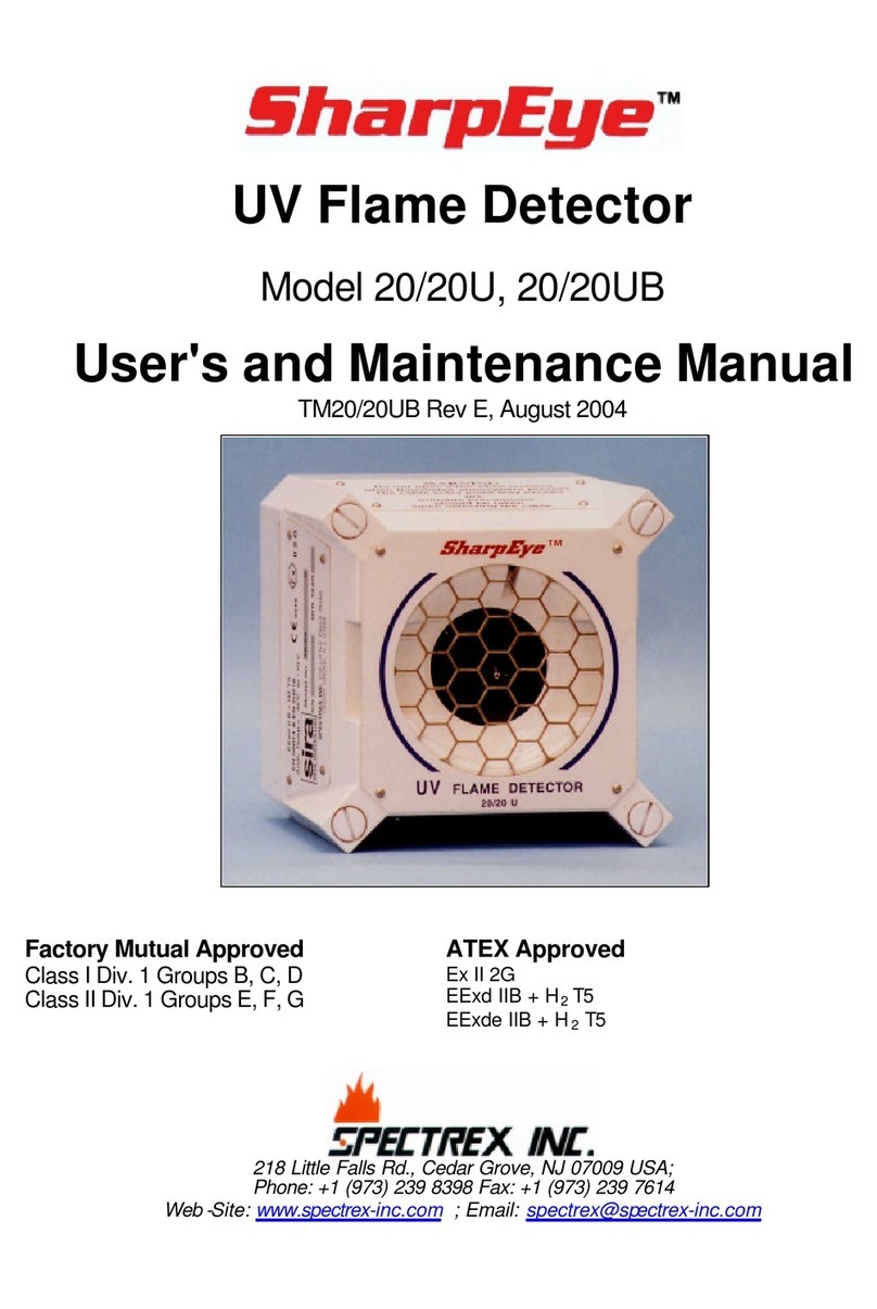
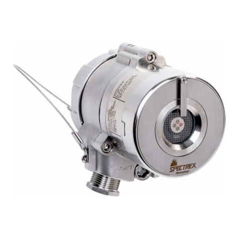
Spectrex SafEye 200 Series Operating instructions

SafEye
Open Path IR Gas Detector
Series 200
User's and Maintenance Manual
Document No. TM792100, Rev. B, October 1997

© 1997- All rights reserved
The SafEye monitoring system described in this document is the property of Spectrex, Inc. It is
furnished under a license agreement and is to be used only in accordance with the terms of the
agreement.
No part of the hardware, software or documentation may be reproduced, transmitted, transcribed,
stored in a retrieval system, or translated into any language or computer language, in any form or
by any means, without prior written permission of Spectrex, Inc.
While great efforts have been made to assure the accuracy and clarity of this document, Spectrex,
Inc. assumes no liability resulting from any omissions in this document, or from misuse of the
information obtained herein. The information in this document has been carefully checked and is
believed to be entirely reliable with all of the necessary information included. Spectrex Inc.
reserves the right to make changes to any products described herein to improve reliability,
function, or design, and reserves the right to revise this document and make changes from time to
time in content hereof with no obligation to notify any persons of revisions or changes. Spectrex,
Inc. does not assume any liability arising out of the application or any use of any product or circuit
described herein; neither does it convey license under its patent rights or the rights of others.
Warning:
This manual should be carefully read by all individuals who have or will have responsibility for
using, maintaining or servicing the product.
The Source and Detector are not field-repairable due to the meticulous alignment and calibration
of the sensors and the respective circuits. Do not attempt to modify or repair the internal circuits or
change their settings, as this will impair the system's performance and void the Spectrex, Inc.
Product warranty.

SafEye Series 200 IR Gas Detector - User’s and Installation Guide SPETCREX INC.
Doc. No. TM792100, Rev. B, Oct. 1997
--i
TABLE OF CONTENTS
11..Product Description.................................................................................................................................1
1.1. General Introduction................................................................................................................................1
1.2. Model Identification.................................................................................................................................1
1.3. Features ...................................................................................................................................................2
1.4. Principle of Operation..............................................................................................................................2
1.4.1. Spectral Finger Print.............................................................................................................................2
1.4.2. Optical Path ..........................................................................................................................................2
1.4.3. Microprocessor Based............................................................................................................................3
1.4.4. GAS SENSITIVITY.............................................................................................................................3
1.4.5. Gas and Mixture Selection and Setting..................................................................................................3
1.5. Description...............................................................................................................................................4
1.5.1. Flash Source Unit (Figures 1-1,1-2).......................................................................................................4
1.5.2. Detector Unit (Figure 3-1).....................................................................................................................4
1.6. Operation Modes......................................................................................................................................6
1.6.1. Normal Mode........................................................................................................................................6
1.6.2. Alignment Mode...................................................................................................................................7
1.6.3. Calibration Mode ..................................................................................................................................7
1.6.4. Mode Selection......................................................................................................................................7
1.7. Visual Indications LEDs ..........................................................................................................................8
1.8. Output Signals .........................................................................................................................................9
1.8.1. 4-20mA Current Output........................................................................................................................9
1.8.2. Relays .................................................................................................................................................10
1.8.3. RS-485 Interface .................................................................................................................................10
1.9. Terminals...............................................................................................................................................11
1.9.1. Detector Terminal...............................................................................................................................11
1.9.2. Flash Source Terminals.......................................................................................................................13
1.10. System Setup........................................................................................................................................14
1.10.1. Detector Setting.................................................................................................................................14
1.10.2. Flash Source Setting..........................................................................................................................16
1.11. Specifications.......................................................................................................................................17
1.11.1. General Specifications......................................................................................................................17
1.11.2. Electrical Specifications ....................................................................................................................17
1.11.3. Mechanical Specifications.................................................................................................................19
1.11.4. Environmental Specifications............................................................................................................20
1.12. Applications.........................................................................................................................................21
22..Installation..............................................................................................................................................23
2.1. Introduction ...........................................................................................................................................23
2.2. General Considerations..........................................................................................................................23
2.2.1. Personnel ............................................................................................................................................23
2.2.2. Tools Required....................................................................................................................................23
2.2.3. Site Requirements ...............................................................................................................................23
2.2.4. Unpacking...........................................................................................................................................24
2.3. Mounting for Standard Installation.........................................................................................................24
2.3.1. Swivel Mount Kit................................................................................................................................25
2.3.2. Swivel Installation (Figure 2-1)...........................................................................................................25
2.4. Mounting for Duct Installation...............................................................................................................27
2.4.1. Duct Mount Set (Figure 2-4) ...............................................................................................................27
2.4.2. Alignment Set (Figure 2-5) and Accessories........................................................................................27
2.4.3. Installation Surface Preparation (Figure 2-2).......................................................................................28
2.4.4. Duct Mount Installation (Figures 2-3, 2-4) ..........................................................................................29
2.4.5. Duct Mount Alignment (Figures 2-4,2-5)............................................................................................32

SPETCREX INC. SafEye Series 200 IR Gas Detector - User’s and Installation Guide
Doc. No. TM792100, Rev. B, Oct. 1997
--ii
TABLE OF CONTENTS (Continued)
2.5. Detector Wiring..................................................................................................................................... 34
2.5.1. Pre-Wiring Requirements.................................................................................................................... 34
2.5.2. Conduit Installation ............................................................................................................................ 35
2.5.3. Harness Connection (Figure 2-6)......................................................................................................... 35
2.5.4. Detector Terminal Wiring................................................................................................................... 37
2.6. Flash Source Wiring .............................................................................................................................. 39
2.6.1. Power Supply...................................................................................................................................... 39
2.6.2. Harness Connection (Figure 1-6)......................................................................................................... 39
2.6.3. Terminal Wiring (Table 1-6)............................................................................................................... 39
33..Operation Procedures ........................................................................................................................... 41
3.1. SafEye Operation................................................................................................................................... 41
3.2. Alignment of Unit (Figures 3-1 through 3-2) ......................................................................................... 41
3.3. Powering on the system.......................................................................................................................... 45
3.4. Safety Precautions.................................................................................................................................. 45
3.5. Zero Calibration..................................................................................................................................... 45
3.6. Calibration Check of Unit...................................................................................................................... 46
44..Maintenance.......................................................................................................................................... 47
4.1. General Maintenance............................................................................................................................. 47
4.2. Periodic Maintenance............................................................................................................................. 47
4.2.1. Routine ("Monthly") Optical Surface Cleaning.................................................................................... 48
4.2.2. Signal Intensity Check (SIC)............................................................................................................... 48
4.2.3. Calibration Check............................................................................................................................... 49
4.2.4. Maintenance Records.......................................................................................................................... 49
4.3. Trouble Shooting ................................................................................................................................... 50
Appendix AAppendix A - Outline Drawings ...........................................................................................................A-1

SafEye Series 200 IR Gas Detector - User’s and Installation Guide SPETCREX INC.
Doc. No. TM792100, Rev. B, Oct. 1997
--iii
List of Figures
Figure 1-1 Flash Source -reflector type............................................................................................................5
Figure 1-2. Flash Source -lens Type................................................................................................................5
Figure 1-3. Detector........................................................................................................................................6
Figure 1-4. Detector’s Wiring Diagram.........................................................................................................11
Figure 1-5. Detector Terminal Board.............................................................................................................12
Figure 1-6. Flash Source Terminal Board......................................................................................................13
Figure 2-1. Detector/Flash Source and Swivel Mount Assembly for Standard Installation .............................26
Figure 2-2. Drilling Layout Dimensions for Duct Installation........................................................................28
Figure 2-3. Detector/Flash Source and Duct Mount Installation scheme........................................................30
Figure 2-4. Duct Mount Installation - Outline Drawing.................................................................................31
Figure 2-5. Telescope Alignment Set.............................................................................................................33
Figure 2-6. Series 400 Detector with Cover (removed) ................................................................................36
Figure 2-7. Typical 4 Wire Controller...........................................................................................................37
Figure 2-8. 4-20 mA Source Output ..............................................................................................................38
Figure 2-9. PC Communication Loop............................................................................................................38
Figure 2-10. Flash Source - Open View.........................................................................................................40
Figure 3-1. Alignment and Mode Selection...................................................................................................42
Figure 3-2. SafEye Flash Source/ Detector Alignment...................................................................................43
Figure A-1. Detector Outline Drawing ........................................................................................................A-1
Figure A-2. Source Outline Drawing: (Lens 65θType) ...............................................................................A-2
Figure A-3. Source Outline Drawing: (Lens 80θType) ...............................................................................A-4
Figure A-4. Source Outline Drawing: (Reflector Type)................................................................................A-5
List of Tables
Table 1-1. Model Selection Guideline for Safeye Series 200 IR Type...............................................................1
Table 1-2. LED Status Indication....................................................................................................................8
Table 1-3. Alignment Indication LED Color ...................................................................................................9
Table 1-4. Standard (default) 4-20 mA Current for the Gas Channel.............................................................10
Table 1-5. Discrete reading of 4-20mA at different detector’s modes.............................................................10
Table 1-6. Flash Source Terminals................................................................................................................13
Table 1-7. SW1 DIP Switches Configuration.................................................................................................14
Table 1-8. Flash Source Flash Rate Configuration.........................................................................................14
Table 1-9. Gas Type Calibration Setup..........................................................................................................15
Table 1-10. SW2 DIP Switches Configuration...............................................................................................15
Table 1-11. SW3 DIP Switches Configuration...............................................................................................16
Table 1-12. Flash Source rate setting............................................................................................................16
Table 1-13. Detector/ Flash Source Height and Weight Vs. Type and Application.........................................19
Table 2-1. Swivel Mount Kit.........................................................................................................................25
Table 2-2. Duct Mount Kit............................................................................................................................27
Table 2-3. Maximum DC Resistance for Copper Wire...................................................................................34
Table 4-1. Maintenance Schedule..................................................................................................................47
Table 4-2. LED Signal Adjustment ...............................................................................................................48
Table 4-3. Trouble Shooting..........................................................................................................................50

SafEye Series 200 IR Gas Detector - User’s and Maintenance Manual SPETCREX INC.
Doc. No. TM792100, Rev. B, Oct 1997
-1-
1. Product DescriptionProduct Description
1. 1. General Introduction
The SafEye Series 200 is an optical open path line of sight gas monitoring system. It
detects and monitors flammable gases and vapors , such as Methane Ethane and
Propane at LELxm concentration in the air. SafEye has a fast response detection time
of no more than 5 seconds. This feature enables an adequate time to take appropriate
safety measures.
The SafEye system uses an open path beam of flash light pulses providing a long line
of sight coverage equivalent to a large number of point detectors along the path. The
transmitted beam covers an IR spectrum from 3µto 4.0µ. The SafEye system
constantly monitors through the collimated beam for the gas or vapor. SafEye
monitors gases over the optical path of up to 160 meter (525ft.).
This manual is designed to provide product description, installation and periodic
maintenance procedures. It is intended to be used by qualified personnel.
1. 2. Model Identification
This manual includes information for Safeye Series 200 models. Table 1-1 identifies
the detector model options in reference to the required gas type and detection range.
Table 1-1. Model Selection Guideline for Safeye Series 200 IR Type
MODEL DISTANCE DETECTOR
(See Note 1 FLASH
SOURCE OPTION
FOR OPTION
FOR
m ft. below for the
“x” suffixes) DUCT
MOUNT St./St.
ENCLOS
URE
201 0.6-2.5 2.0-8.2 OPIF000x OPSFI0x YES YES
202 2.5-10 8.2-3.3 OPIF100x OPSFI0x YES YES
203 10-40 33-131 OPIF100x OPSFI1x NO YES
204 15-60 49-192 OPIF100x OPSFI2x NO YES
224 25-80 82-262 OPIF101x OPSFI2x NO YES
225 50-160 164-525 SD200SN OPSFI2x NO NO
Notes:
1. For standard installation add “S” suffix. For duct installation add “D” suffix. For
St. St. version add “St” suffix after the “D” or the “S” suffix.
2. Model SD200SN is not detailed in this document. Details are given at different
document.

SafEye Series 200 IR Gas Detector - User’s and Maintenance Manual SPETCREX INC.
Doc. No. TM792100, Rev. B, Oct..1997
-2-
1. 3. Features
•Detection Range up to 160m (525 ft.).
•Simultaneous detection of Hydrocarbon Flammable Gases and mixtures.
•High Sensitivity (LELxm)
•Fast Response
•Explosion Proof Enclosure
•Automatic Gain Control suitable for harsh environments
•Completely Immune to industrial and environmental radiation sources
•Can be connected to commonly used control panels
•Standard 4-20 mA Output & Dry Contact Relays
•RS-485 Output for a PC Communications data bus.
•Can be integrated into a network for a maximum of 64 SafEye systems
•Easily adaptable for field usage
•Simple Installation, Alignment, and Calibration
•Magnetic Mode Selector to change to alignment and calibration modes easily
•Minimal Periodic Maintenance
•Background Zero Calibration
1. 4. Principle of Operation
The SafEye system detects gases through a dual spectral range monitoring, analyzing
the absorption of radiation caused by gases in the atmosphere and comparing it (ratio)
to background atmospheric absorption.
1. 4. 1. Spectral Finger Print
Each hazardous material is detected by a specific sensor selected according to its
specific spectral absorption or "finger print". There are three IR sensors that can be
used for combustible gases. The detection process involves two separate filters, one
transmitting radiation which is absorbed by a particular gas and one which is not
sensitive to it.
1. 4. 2. Optical Path
The presence of hazardous airborne vapors, gases, or aerosols in a monitored area is
detected when the defined substance crosses the optical path between the radiation
source unit and the detector.
Hazardous materials present in the atmosphere cause a absorption of the radiation
pulse in the optical path between the radiating source and the detector unit at some
specific wavelengths. This causes a change in the signal intensity received by the
detector.
The system analyzes the defined open path at several spectral bands specific to the
materials being monitored. The Automatic Gain Control (AGC) unit compensates for
environmental disturbances such as fog, rain, etc., through a constant comparison
with its dual spectral beam.

SafEye Series 200 IR Gas Detector - User’s and Maintenance Manual SPETCREX INC.
Doc. No. TM792100, Rev. B, Oct 1997
-3-
1. 4. 3. Microprocessor Based
The incoming signals are analyzed by the built in microprocessor. A sophisticated
mathematical algorithm that calculates between the various functions of the detected
signal thresholds, and rate of rise is employed. Statistics, ratio algorithms, correlation,
data communications, diagnostics and other functions are performed.
1. 4. 4. GAS SENSITIVITY
The Safeye IR Model uses wavelengths around 3.4µspectral band to measure air
flammability potential between source and detector. At this wavelength all
hydrocarbon materials have a strong absorption peak. This peak enables the detector
to achieve both regular sensitivity of 0-5 LELxm and high sensitivity of
0-2 LELxm according dip switch setting. However since the desired detection
information is air flammability and the actual measurement is radiation absorption
around the 3.4µspectral band, the detector has a difference in sensitivity to different
gases or gas combinations.
This difference in sensitivity is irrelevant if in the protected area the gas composition is
known. However, if in a protected area the gas composition can vary substantially,
then the difference in sensitivity should be considered in determining the detector
calibration.
Under/Over Estimation:
In cases where a detector is calibrated to the least sensitive gas composition possible
in a protected area, then it will over estimate the actual flammability of all other gas
compositions. For example, if calibrated for methane and the mixture is 98%
Methane, 2% Propane, the over estimation factor will be 2.5. The detector will read
3 LELxm, when the actual gas concentration mixture between source and detector is
1.2 LELxm. Calibrating the detector to the above mentioned gas mixture may result
in under estimation of actual air flammability for pure methane. An under estimation
of 0.4 will result in the detector reading 3 LELxm only when the actual gas
concentration between source and detector is 7.5 LELxm.
From the above, it is clear that over estimations can result in false alarms and under
estimations can result in the detector not responding to a real alarm situation, hence in
a protected area a substantial under estimation of gas calibration is inadmissible while
a substantial over estimation should be avoided if possible.
1. 4. 5. Gas and Mixture Selection and Setting
At the 3.4µspectral band of the Safeye, the least sensitive gas is 100% methane and
the highest sensitive gases are various mixtures of Methane with heavier paraffins
where the Methane percentage is less than 90%. For pure Ethane the sensitivity is
close to the high sensitivity gases and for pure Propane it lies somewhere between the
two extremes. Every Safeye has a built-in 4 gas calibration settings that can be
changed by dip switches.

SafEye Series 200 IR Gas Detector - User’s and Maintenance Manual SPETCREX INC.
Doc. No. TM792100, Rev. B, Oct..1997
-4-
The calibration settings are designed for use in various applications:
Gas 1 - Is pure methane and is for use in methane storage and piping
applications
Gas 2 - Universal oil and gas production mixture to be used in all cases where
methane concentration in the mixture does not exceed 98%. It can also
be used for pure Ethane applications.
Gas 3 - Is pure propane and is good for propane/butane detection including LPG
etc.
Gas 4 - Is 99% methane and 1% propane and is for use in detecting methane
mixture with heavier gases where the methane component can vary
between 100% to 95%. It is also good for protecting areas where a
leak can be either pure methane or pure propane.
The four internal gas calibrations cover most of the flammable gas detection
applications. Actual selections should be made by the user in consultation with
experts to provide for safety requirements. However, for special cases where none of
the four calibrations are O.K., Spectronix, through local agents can advise how to
calibrate a SafEye detector to any specific gas.
1. 5. Description
The system comprises two main units; the Flash Source and the Detector. The SafEye
system detects gases over an open path transmitted from the Flash Source to the
Detector.
1. 5. 1. Flash Source Unit (Figures 1-1,1-2)
The Flash Source unit emits IR radiation pulses, in a collimated beam (for maximum
intensity) to the detector unit. The source is available in three different types as
follows:
a. Reflector type, model OPSFI0x.
b. 65φlens type, model OPSFI1x.
c. 80φlens type, model OPSFI2x.
Refer to Table 1-1 for selection of the suitable Flash Source for the Detector.
1. 5. 2. Detector Unit (Figure 3-1)
The detector's sensors receive the transmitted pulsed radiation signals from the Flash
Source. The signals are then amplified and fed into an analog to digital signal
converter to be processed by the internal microprocessor.
When the signals drop below a prescribed level, the internal microprocessor will
compensate for them. This will allow the signal to be maintained even in severe
weather conditions. The data is sent to the output interface section. The signals can be
sent to a standard control panel or to a central computer.

SafEye Series 200 IR Gas Detector - User’s and Maintenance Manual SPETCREX INC.
Doc. No. TM792100, Rev. B, Oct 1997
-5-
The Series 200 Detector is available in three basic types:
a. Without lenses - for short range installation.
b. With lenses - for medium range installation.
c. With lenses - for long range installation.
.
Figure 1-1 Flash Source -reflector type
a. 80φφ Lens b. 65φφ Lens
Figure 1-2. Flash Source -lens Type

SafEye Series 200 IR Gas Detector - User’s and Maintenance Manual SPETCREX INC.
Doc. No. TM792100, Rev. B, Oct..1997
-6-
Figure 1-3. Detector
1. 6. Operation Modes
The SafEye system has three operation modes; Normal, Alignment and Calibration.
The Normal mode is used for basic operation. The Alignment and Calibration modes
are used for alignment and calibration respectively.
1. 6. 1. Normal Mode
This mode is used for gas detection. The following status signals are possible:
Normal, Warning, Alarm, and Fault (see Table 1-2 for visual indications).
In the Normal status the signals received from gas detection is at safe levels.
In the Warning status gases have been detected at Warning levels.
In the Alarm status gases have been detected at Alarm levels.
In the Fault status there are three fault types:
• Fault 1
In this case detection is disabled due to blockage, poor alignment, very low signal
or in the case of partial or full signal blocking. In this case the detector’s proper
operation can be restored during operation if the fault vanishes.
• Fault 2
In this case of fault the Detection is disabled due to electrical/software running
failure or central device (memory, processor) fault. Such fault causes total failure
of the detector.

SafEye Series 200 IR Gas Detector - User’s and Maintenance Manual SPETCREX INC.
Doc. No. TM792100, Rev. B, Oct 1997
-7-
• Low Voltage Fault
In this case detection is disabled due to low voltage supplied to the detector. The
detector returns to proper operation only when proper voltage level restores.
1. 6. 2. Alignment Mode
This mode is used when the received signal needs to be measured (i.e. Installation &
Periodic Maintenance). LED indications represent the received signal for precise
alignment. There is a temporary Standby Mode to give the option of switching from
Alignment Mode to Calibration Mode.
1. 6. 3. Calibration Mode
This mode zeros the gas detection reading . It should only be performed when there
is no combustible gases (or insignificant) blocking between the Flash Source and
Detector units, and in proper weather conditions. After calibration the detector
switches to Normal Mode.
1. 6. 4. Mode Selection
A Magnetic Mode Selector is used to change to alignment and calibration modes by
placing the magnet on the side of the detector .

SafEye Series 200 IR Gas Detector - User’s and Maintenance Manual SPETCREX INC.
Doc. No. TM792100, Rev. B, Oct..1997
-8-
1. 7. Visual Indications LEDs
there are two indication lights (LEDs) located in the detector’s front window referred
to as the right and left LEDs. They display red, orange and green light that can be
solid or blinking.
Table 1-2. LED Status Indication
STATUS REMARKS LEFT
LED RIGHT
LED LED
STATUS 4-20mA
OUTPUT
Normal Off Green Constant 4 mA
Warning See Note 4 Off Red Constant 14 mA
Alarm See Note 4 Red Red Constant 19 mA
Fault 1 Off Orange Constant 2 mA
Fault 2 Orange Orange Constant 0 mA
Low
Voltage Orange Orange Both LEDs
Blink at
rate of 2 Hz
0 mA
Alignment
Mode first Received the
intensity compared to
the last calibration:
The intensity is min.
80% of the last
calibration intensity
Green Green 0 mA
80% - 60% Green Orange 0 mA
60% or less Orange Red 0 mA
Alignment
Mode After 20 seconds the
color represents the
signal intensity
(See Note 2).
See
Note 1 See
Note 1 0 mA
Standby
mode Green Green Both LEDs
blink
alternately
at a rate of
2Hz.
0 mA
Calibration
mode See Note 3 Off Off 0 mA

SafEye Series 200 IR Gas Detector - User’s and Maintenance Manual SPETCREX INC.
Doc. No. TM792100, Rev. B, Oct 1997
-9-
Notes:
(1). The number of blinks shows the intensity of the received signals while the color
represents the gain (see Table 1-3). The left LED shows the “tens” unit of the
number while the right LED displays the “one” unit of the number of the signal
intensity. Each LED will blink 0 to 9 times (9 being the maximum possible
signal intensity). When the left LED has reached its highest signal look at the
right LED for fine adjustment.
Table 1-3. Alignment Indication LED Color
Left LED Right LED Gain
Red Red 3
Orange Orange 2
Green Orange 1
Green Green 0
(2). After 20 minutes at alignment mode the detector will return to normal mode.
(3) After zero calibration is finished, the detector will return to normal mode and
the signal intensity will be saved for next alignment comparison.
(4) The 4-20mA level in this Table refers to discrete indication option. A different
(continuous reading) option is described later in section 1.8.1.
1. 8. Output Signals
The Safeye system provides the following outputs:
•Standard 4-20 mA port
•Three dry contact relays
•Optional RS-485 Output for PC Communications
1. 8. 1. 4-20mA Current Output
The 4-20mA output can provide the detector status measurement in one of the two
following methods:
1. It can be measured proportionally (standard) showing a continuous reading of the
exact gas concentration (see Table 1-4).
2. It can be a discrete indication according to the detector mode or the Warning or
Alarm signal at a defined gas concentration. Setting of this method can be done
by SW3-2 selection.
For this method the default setting is described in Table 1-5.
The 4-20mA functions as current source.
It is provided by setting of DIP switches SW2-7 and SW2-8 to on position.
The maximum permitted load resistance for the 4-20mA output is 600 ohms. The
minimum permitted load resistance is 100 ohms.

SafEye Series 200 IR Gas Detector - User’s and Maintenance Manual SPETCREX INC.
Doc. No. TM792100, Rev. B, Oct..1997
-10-
Table 1-4. Standard (default) 4-20 mA Current for the Gas Channel
Current Status and Description
0mA+0.5mA Fault 2 or Low Voltage
2mA±0.5mA Fault 1
4mA±0.5mA No gas detection
4-20mA Continuous measuring of gas concentration at
a range between 0 and 5 LELxm
21mA Concentration is over the range limit (more
than full scale concentration).
Table 1-5. Discrete reading of 4-20mA at different detector’s modes
Current Reading Mode %LELxm
Setting
0+0.5mA Fault 2 or Low Voltage -
2±0.5mA Fault 1 -
4±0.5mA Standby 0
14±0.5mA Warning 100
19±0.5mA Alarm 250
1. 8. 2. Relays
The detector includes three following relays:
− Fault relay
− Alarm relay
− Accessory relay
The normal position of the alarm and warning relays is open. When in the alarm or
warning status the appropriate relay is closed. The normal position for the fault relay
is closed, and when it is in the fault situation the relay is open.
1. 8. 3. RS-485 Interface
The RS-485 input/output sends complete data information to a PC and receives data
or control commands from the PC. The communication with the PC is operated
through this interface is executed only when used with an appropriate host software.
The following PC minimal hardware requirements are as follows:
•386 PC using DOS Ver. 5.0 or higher
•1 MB RAM.
•2 MB free hard disk space.
•1.2 or 1.44 MB floppy drive
•Color VGA
•RS-485 Interface Card to be defined as COM1 or COM2. Isolated
Adapter is preferred.

SafEye Series 200 IR Gas Detector - User’s and Maintenance Manual SPETCREX INC.
Doc. No. TM792100, Rev. B, Oct 1997
-11-
1. 9. Terminals
Terminal outputs are described for the Detector and the Flash Source.
1. 9. 1. Detector Terminal
a. Terminal Wiring (Figure 1-4) displays a schematic diagram of the terminals
and Figure 5 shows their location.
INCLUDEPICTUREORDTEXT
1
2
6
3
4
5
7
8
9
13
11
10
12
14
Detector is Activated).
(N.O.)
Return
(18-32VDC)
Power
N.C.
COM.
N.O.
Alignment Strobe
Fault Relay
(Closed Contact When
Alarm Relay
Accessory Relay
Earth Ground
4-20mA IN(-)
4-20mA OUT(+)
N.O.
R.S.-485 (-)
R.S.-485 (+)
Screw
Grounding
Figure 1-4. Detector’s Wiring Diagram

SafEye Series 200 IR Gas Detector - User’s and Maintenance Manual SPETCREX INC.
Doc. No. TM792100, Rev. B, Oct..1997
-12-
LEGEND:
1. Detector Cover
2. Terminal Board
3. Terminal Screw
4. Securing Cable
5. Conduits
Figure 1-5. Detector Terminal Board

SafEye Series 200 IR Gas Detector - User’s and Maintenance Manual SPETCREX INC.
Doc. No. TM792100, Rev. B, Oct 1997
-13-
1. 9. 2. Flash Source Terminals
Figure 6 shows the terminal board and Table 6 describes their use.
INCLUDEPICTUREORDTEXT
J
J
N
O
S
Figure 1-6. Flash Source Terminal Board
Table 1-6. Flash Source Terminals
Flash Source
Terminal # Description
1VIN
2RTN

SafEye Series 200 IR Gas Detector - User’s and Maintenance Manual SPETCREX INC.
Doc. No. TM792100, Rev. B, Oct..1997
-14-
1. 10. System Setup
1. 10. 1. Detector Setting
The detector consists of the following DIP Switches which enable the user to adapt
the detector operation to specific application:
SW1 - Function Selection Switch. Contains. 8 DIP Switches. Used for Calibration of
different gas selection, response time control and Relays response
configuration.
SW2 - Address Selection Switch. Contains 8 DIP Switches. Used for Detector’s
address setting and 4-20mA output configuration setting.
SW3 - Alarm Options Selection Switch. Contains 4 DIP Switches. Used for
Detector’s Alarm Latching configuration and 4-20 mA level reading
configuration.
Function Selection Switch:
Table 1-7 describes SW1 DIP Switches position and the required function for setting
the detector. according to the necessary configuration
Table 1-7. SW1 DIP Switches Configuration
Switch
No. off position on position Default
setting
1. Detection speed control bit 0 at “0”
(see note 1 below) Detection speed control bit 0 at “1”
(see note 1 below) on
2. Detection speed control bit 1 at “0”
(see note 1 below) Detection speed control bit 1 at “1”
(see note 1 below) off
3. Gas type control bit 0 at “0
(see note 2 below)” Gas type control bit 0 at “1”
(see note 2 below) off
4. Gas type control bit 1 at “0
(see note 2 below)” Gas type control bit 1 at “1”
(see note 2 below) off
5. Full scale sensitivity is 0-5 LELxm Full scale sensitivity is 0-2 LELxm off
6. Zero calibration is performed
according to background Gas level detection performed without
background Zero calibration off
7. Accessory Relay is activated at
Warning level Accessory Relay is activated at Alarm
level (with the Alarm Relay) off
8. Accessory Relay is activated
according to SW1-7 position Accessory Relay is Activated at Power
on continuously ( used as End of Line) off
Notes:
1. Detection flashes rate can be selected by pre-setting of SW1-1 and SW1-2
according to the following table. There are two bits which provides four Flash
Source rates. Same Flash rate should be set also at the Flash Source.
Table 1-8. Flash Source Flash Rate Configuration
bit #0 position
(SW1-1) bit #1 position
(SW1-2) Source flash Rate
(flashes/second)
off off 0.5
on off 1
off on 2
on on 4

SafEye Series 200 IR Gas Detector - User’s and Maintenance Manual SPETCREX INC.
Doc. No. TM792100, Rev. B, Oct 1997
-15-
2. Four Gas types can be selected for maximum compatibility to Gas spectral
properties. The selection of the appropriate type is defined by pre-setting of
SW1-3 and SW1-4 according to the following table:
Table 1-9. Gas Type Calibration Setup
bit #0
position
(SW1-3)
bit #1
position
(SW1-4)
Detected Gas type Gas type as defined in
Section 1.4.5
off off Methane Gas 1
on off Mixture Gas 2
off on Propane Gas 3
on on Mixture Gas 4
Address Selection Switch
The Address selection Switch provides up to 64 different addresses for the detector
upon a network installation. Each detector can be recognized at its specific address in
RS485 network. The address should be determined by a pre-setting of SW2-1 to
SW2-6 switches.
SW2 also provides the user to select configuration of the 4-20mA output between
either Source type or Sink type according the requirements of the interfaced
controller. This can be done upon pre-setting of SW2-7 to SW2-8.
Attention !
SW2-7 and SW2-8 should be always at on.
Table 1-10 describes SW2 DIP Switches position and the required function for setting
the detector. according to the necessary configuration
Table 1-10. SW2 DIP Switches Configuration
Switch
No. Switch Definition off position on position Default
setting
1. Address bit 0 (LSB) 0 1 off
2. Address bit 1 0 1 off
3. Address bit 2 0 1 off
4. Address bit 3 0 1 off
5. Address bit 4 0 1 off
6. Address bit 5 (MSB) 0 1 off
7. 4-20mA direction
setting (1) N/A 4-20mA output at
source position on
8. 4-20mA direction
setting (2) N/A 4-20mA output at
source position on
This manual suits for next models
6
Table of contents
Other Spectrex Smoke Alarm manuals
Popular Smoke Alarm manuals by other brands

Teletek electronics
Teletek electronics SensoIRIS M140 IS manual

teko
teko ASTRA ZITADEL quick start guide

AJAX
AJAX FireProtect Plus quick start guide
NAPCO
NAPCO GEMC-WL-SMK installation instructions
Ferguson
Ferguson FS2SD user manual

Kidde Technologies
Kidde Technologies SR2033 Operation & maintenance manual
