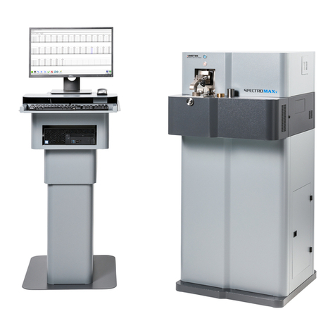
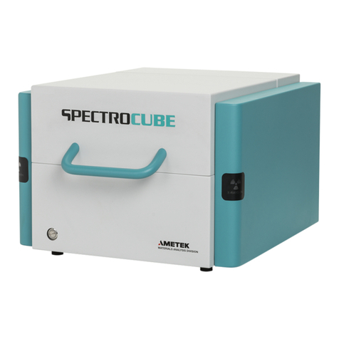
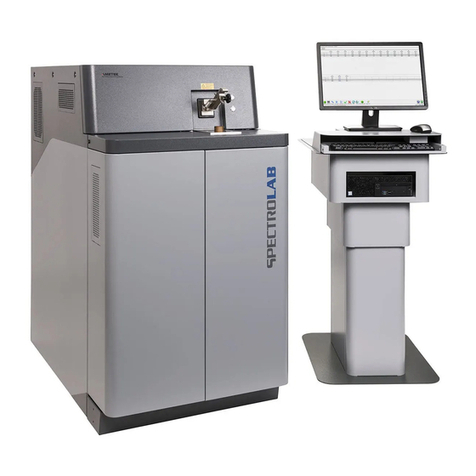
SPECTRO XEP05 User manual

DasverknüpfteBildk ann nichtangezeigtwerden.Möglicherweisewurdedie Dateiverschoben, umbenanntoder gelöscht.StellenSie sicher, dass d ie Verkn üpfung aufd ie
korrek te Dateiund denk o rr ek ten Speicherort zeigt.
SPECTRO XEPOS
Benchtop XRF Spectrometer
Original operating instructions


SPECTRO XEPOS — 19.01.2017 — 3
Table of Contents
1Description of instrument ....................................................................................5
1.1Description .......................................................................................................................... 5
1.2Function .............................................................................................................................. 5
1.3Overview ............................................................................................................................. 6
1.3.1Configuration ......................................................................................................... 6
1.3.2Instrument (front) ................................................................................................... 7
Opening and closing the sample chamber lid ....................................................... 8
1.3.3Instrument (back)................................................................................................... 9
1.3.4Sample chamber ................................................................................................. 10
1.3.5Sample chamber - additional components.......................................................... 11
1.3.6Sample tray ......................................................................................................... 11
2Safety................................................................................................................12
2.1Symbols used ................................................................................................................... 12
2.2User information................................................................................................................ 13
2.3Intended use ..................................................................................................................... 13
2.4Prohibited operating conditions ........................................................................................ 14
2.5Residual risks.................................................................................................................... 14
2.6Radiation protection advice .............................................................................................. 16
2.6.1Other countries .................................................................................................... 16
3Technical data...................................................................................................17
4Transportation/Setting-up .................................................................................18
4.1Storage ............................................................................................................................. 19
4.2Gas supply (optional)........................................................................................................ 19
4.3Vacuum (option)................................................................................................................ 20
4.4Uninterruptible power supply – UPS (option) ................................................................... 21
5Operation ..........................................................................................................23
5.1Displays ............................................................................................................................ 23
5.1.1Screen – Routine dialog ...................................................................................... 23
5.1.2Beam Stop display on the instrument.................................................................. 24
5.2Switching on the instrument.............................................................................................. 25
5.3Proceed with the start-up test ........................................................................................... 27
5.3.1Checking the safety circuits on the sample chamber lid ..................................... 27
5.3.2Checking the safety circuit on the filter changer ("Beam Stop").......................... 28
5.3.3Initialization of the stepping motors ..................................................................... 29
5.3.4Automatic verification of the safety circuits after one month ............................... 30
5.4Switching off the instrument.............................................................................................. 31
5.5Standby mode................................................................................................................... 32
5.6Measuring procedure........................................................................................................ 33
5.6.1Preparing the measuring procedure.................................................................... 33
How to measure different samples...................................................................... 34

— 4 SPECTRO XEPOS — 19.01.2017
How to measure cuvettes (powder or liquid) ....................................................... 34
How to measure powder pallets .......................................................................... 35
How to measure glass or melting pellets............................................................. 35
How to measure large samples ........................................................................... 36
5.6.2Proceed with the measurement ........................................................................... 37
How to change/remove the sample tray .............................................................. 38
5.7Dust protection shutter / beam stabilization vacuum shutter (option)............................... 39
Dust protection shutter......................................................................................... 39
Beam stabilization vacuum shutter...................................................................... 39
6Maintenance by the operator............................................................................ 40
6.1Operator maintenance plan............................................................................................... 40
6.2Energy channel recalibration (MCA) ................................................................................. 42
6.3Standardization (Global recalibration)............................................................................... 43
6.4Clean the sample tray ....................................................................................................... 44
6.5Clean the sample chamber ............................................................................................... 44
6.6Replacing the adhesive film in the discharge reservoir .................................................... 45
6.7Replacing the tray pads .................................................................................................... 46
6.8Insert the film for the "liquid protect" sample cup.............................................................. 47
6.9Replacing the filter mat ..................................................................................................... 49
6.10Dust protection shutter / beam stabilization vacuum shutter (option) — Clean O-ring..... 50
6.11Troubleshooting ................................................................................................................ 51
7Spare parts and consumables.......................................................................... 55
8De-commissioning............................................................................................ 55
9Manufacturer address ...................................................................................... 55
10EC Declaration of Conformity........................................................................... 56

Description of instrument
SPECTRO XEPOS — 19.01.2017 — 5
1 Description of instrument
1.1 Description
Designation: SPECTRO XEPOS
Model: XEP05
Type: 76004852
1.2 Function
X-rays excite the atoms of the sample, causing them to emit radiation. This
radiation is measured by a semiconductor detector.
To achieve a higher sensitivity, the exciting radiation can be optimized by using X-
ray optical elements or filters.
The instrument comes with a prepared analysis method. Data are already stored
in the instrument's memory. The measured values are compared with these data.
After the measurement is complete, the results of a sample relating to an unknown
composition are displayed on the screen.
The sample material may be solid, liquid or in powder form, see Chapter "How to
measure different samples".

Description of instrument
— 6 SPECTRO XEPOS — 19.01.2017
1.3 Overview
1.3.1 Configuration
The instrument is available in various configurations. Depending on the
application/requirement, the instrument is equipped with the following X-ray optics:
Direct excitation
Direct excitation and single polarization channel
Direct excitation and dual polarization channel
Depending on the application / requirement, the following expansions are
available:
Sample spinner
Helium flushing
Vacuum pump
Active pile-up suppression
Dust protection shutter / beam stabilization vacuum shutter

Description of instrument
SPECTRO XEPOS — 19.01.2017 — 7
1.3.2 Instrument (front)
Fig. 1: Front view
No. Component
1 Sample chamber lid
2 Ventilation slots with filter mat
3 Beam stop display Open/closed (Open = red/closed = green)
X-ray display On/Off (On = orange/Off = off),
see also Chapter 5.1.2.
1
2
3
3

Description of instrument
— 8 SPECTRO XEPOS — 19.01.2017
Opening and closing the sample chamber lid
Caution! Risk of crushing injuries!
When closing the sample chamber lid, there is an inherent risk of crushing injuries.
When closing the sample chamber lid keep the fingers out of the sample
chamber.
Fig. 2
No. View
1 Sample chamber lid closed
2 Sample chamber lid open
When pressing slightly against the handle, the sample chamber lid can be pushed
back and locked into place. In order to open the cover, slightly press against the
handle and pull on the sample chamber lid.
12

Description of instrument
SPECTRO XEPOS — 19.01.2017 — 9
1.3.3 Instrument (back)
Fig. 3: Rear view
No. Component No. Component
1 Type plate with serial number,
date of production, max.
parameters of the X-ray tube
5 Power supply connection for
vacuum pump (1000 W max.)
2 PC/Ethernet conviction (using the
LAN cable included in delivery)
6 Power In (max. 1200 W)
3 Helium supply line connection 7 Key-operated switch On/Off
4 Vacuum hose connection
Note
Set up the instrument to ensure the power isolators (switches and power cable)
can be easily reached.
1
3
2
45
67

Description of instrument
— 10 SPECTRO XEPOS — 19.01.2017
1.3.4 Sample chamber
Fig. 4
No. Component
1 Sample tray locking device
2 Sample tray (different models available)
3 Analysis position (position of the sample during the measurement)
4 Tray handle
5 Tray screw
1
4
2
3
5

Description of instrument
SPECTRO XEPOS — 19.01.2017 — 11
1.3.5 Sample chamber - additional components
Fig. 5
No. Component
1 Sample tray support
2 Discharge reservoir
3 Sample spinner drive (optional)
4 Dust protection shutter or beam stabilization vacuum shutter (optional)
5 Active pile-up suppression (optional)
6 Tray pad (3 pcs. Installed inside)
7 Tray pad rotation tray (7 pcs., installed outside)
Single sample rotation unit (optional), (not shown for clarity)
1.3.6 Sample tray
The sample trays come in different versions.
12 sample positions for Ø 40 mm samples with an adapter for Ø 32 mm
samples
25 sample positions for Ø 20 mm samples
8 sample positions for rotating samples for Ø 40 mm samples or
6 sample positions for rotating Ø 52 mm samples
4
3
5
1
2
6
7

Safety
— 12 SPECTRO XEPOS — 19.01.2017
2 Safety
Every user of the instrument must have understood these operating instructions.
This applies in particular to the safety regulations.
2.1 Symbols used
The following symbols are used in these abbreviated operating instructions and/or
on the instrument.
If required, additional important information is available in connection with these
symbols.
Caution! Risk of injury!
Danger! Risk of electric shock!
Caution! Fire hazard!
Caution! Danger of poisoning!
Caution! Risk of crushing injuries!
Caution! Ionizing radiation!
Notice!
Warns of activities or conditions that may adversely affect the safety or function of
the instrument.
Note
Displays information that is important for the correct and safe use of the instrument

Safety
SPECTRO XEPOS — 19.01.2017 — 13
2.2 User information
Compliance with all safety instructions is mandatory. It's for your own safety.
Carry out only operator maintenance work that is described in chapter 6. The
operating personnel is not permitted to proceed with any other maintenance
work. Any further services (e.g. technical maintenance) or repairs must only
be performed by service personnel that are authorized by the manufacturer.
Comply with all safety instructions and accident prevention regulations at all
times while operating and maintaining the instrument. This regulation is, for
example, DIN EN 61010 or any other comparable national standard.
The safety measures must be checked following every technical maintenance
or repair activity. This check must be performed according to VBG4/DIN EN
61010 or a comparable national standard.
Compliance with the maintenance schedule specified by the manufacturer is
mandatory, All maintenance activities must be recorded. This will maintain the
operational safety of the instrument.
Never tamper with the safety devices! If you feel that a safety device does not
work properly, shut down the instrument immediately! Please contact your
Service Center.
Only genuine spare parts must be used when repairing the instrument. The
use of non-genuine spare parts will make the CE Declaration of Conformity
null and void.
The instrument may only be connected to the power supply with a protective
grounding conductor.
If an instrument is positioned on a sloped surface, it may roll away during the
operation. Secure the instrument while in operation. This applies also when
the instrument is being transported.
Compliance with the relevant safety regulations when using tools and
operating equipment is mandatory.
Compliance with the safety instructions when handling and preparing the
samples (material safety data sheet) is mandatory. The contact with certain
metals, plastics, powders, liquids, or other materials can be hazardous to
health.
2.3 Intended use
The spectrometer must only be used to analyse liquid substances or powdery
materials inside special containers (e.g., cuvette, sample cup). Solid samples, e.g.,
metal parts, may be analyzed outside of these containers.

Safety
— 14 SPECTRO XEPOS — 19.01.2017
2.4 Prohibited operating conditions
Do not operate the instrument if one of the following conditions exists:
If the instrument is faulty or damaged.
If the ambient conditions do not comply with the specification.
2.5 Residual risks
This instrument has been manufactured in accordance with the state of the art.
Nevertheless, a residual risk cannot be completely excluded.
Danger! Risk of electric shock!
The spectrometer produces electric voltages of up to 60 kV.
Shut down the instrument immediately if damaged.
Caution! Danger of poisoning!
The ray exit window of the X-ray tube and the detector window contain beryllium.
Vapors or dust of beryllium and its compounds are toxic and hazardous to your
health when inhaled.
Do not touch this window.
Should you have broken the beryllium window of the detector, immediately
seal off the measurement window of the spectrometer with adhesive tape.
This ensures that no broken beryllium window pieces can leave the
spectrometer. Switch off the spectrometer and inform the service department
of SPECTRO. The detector and the spectrometer can no longer be used.
Caution! Risk of crushing injuries!
When closing the sample chamber lid, there is an inherent risk of crushing injuries.
When closing the sample chamber lid keep the fingers out of the sample
chamber.

Safety
SPECTRO XEPOS — 19.01.2017 — 15
Caution! Ionizing radiation!
This spectrometer operates with ionizing radiation (X-rays). The safety devices
ensure that the spectrometer can be operated only in a safe, closed and shielded
condition.
Never tamper with the safety devices.
If you are concerned that the safety devices do not work properly, shut down
the spectrometer immediately. Please contact your Service Center.
The results of the ambient dose rate measurements are an integral part of the
documentation supplied with the spectrometer (radiation protection
certificate).
The condition of the beam stop (it cannot be seen from the outside since it is
immediately in front of the X-ray tube) is shown by the combination display
"Beam-Stop / X-Rays ON".
"Green" indicates that the Beam Stop is on, "Red" indicates that the Beam
Stop is open. If the Beam Stop is opened, this always caused the sample
chamber lid to be locked. An orange-colored LED indicates the operation of
the X-ray tube. See also Chapter 5.1.2 on page 24.
Note
If the instrument is in its normal operating mode (standby or measuring mode), it
produces ionizing radiation (X-rays).
The safety circuits in the instrument are designed to ensure the sample chamber
lid is always locked during the measurement.
For your safety, the safety circuits are checked automatically. Therefore, when
starting the software, a message is displayed requesting the opening and closing
of the cover (referred to as Start-up test, see Chapter 5.3).
Automatic safety circuit checks must be carried out at least once a month. If the
device has not been switched off and switched on again at the main switch for one
month, the software prompts you to do so (see also chapter 5.3.4). Three days
before the deadline, a first reminder appears in the status display of the software.

Safety
— 16 SPECTRO XEPOS — 19.01.2017
2.6 Radiation protection advice
Please observe the national safety and approval regulations in force in your
country and state!
2.6.1 Other countries
The operation of the instrument may require official approval in other countries.
Compliance with the national safety and approval regulations in force in your
country and/or state is mandatory! Please contact the responsible local approval
authority.

Technical data
SPECTRO XEPOS — 19.01.2017 — 17
3 Technical data
Description Value
Instrument height 465 mm (18.3“)
Instrument width 618 mm (24.3“)
Instrument depth 730 mm (28.8“)
Instrument weight 65 kg (143 lbs) approx.
Place of installation Inside of dry, dust-free rooms up to an
altitude of 2,000 m above sea level,
vibration-resistant (not subject to impact
and vibration loads)
Operating voltage range 90 - 253 VAC, 50/60 Hz
Spectrometer power input max. 1,200 W (without PC)
Fuse 16 A (slow-blow)
Temperature range
Storage room temperature range
+10 to +35°C (50 to 95°F)
-10 to +50°C (14 to 122°F)
Optimal temperature range (within
specifications)
+20°C – +25°C (68 °F – 77 °F)
Air humidity 10 to 80% (non-condensing) at 25°C
10 to 75% (non-condensing) at 30 °C
Protection class/contamination class IP20 (DIN 40050), contamination class II
(laboratory environment)
EMC environment Normal laboratory environment
Helium gas flushing (option)
Pressure 1.0 – 3.0 bar; (15 – 44 psi)
Quality ≥99.996% (4.6)
Consumption typically 4.5 L per analysis
Vacuum (option)
End pressure/operating pressure < 5 mbar (0.07 psi)
Voltage supply 110 V/230 V (instrument-controlled)

Transportation/Setting-up
— 18 SPECTRO XEPOS — 19.01.2017
4 Transportation/Setting-up
Only instructed personnel may unpack, install, and set up the instrument.
Note! Measurement errors!
Shocks to the instrument during the measuring process may result in
measurement errors.
Therefore, shocks to the instrument when taking measurements must
be avoided.
Avoid mechanical impacts.
Measurement errors may result from temperature differences inside the
instrument.
Install the instrument so that it cannot heat up on one side only.
Observe the following information regarding the instrument's installation/transport:
Use the adjustable legs of the instrument in order to compensate for a slight
unevenness.
Always transport the instrument in a horizontal position, ensuring its legs are
pointing down.
Always keep the instrument upright when transporting it! To do this,use your
left and right hand to reach underneath the plastic housing. Remember that
the center point of gravity of in the front of the instrument.
Save the transport package in case you have to ship the instrument to the
service department at a later date.
All connections are located at the back panel.
When setting up the spectrometer, ensure all sides are easy to access
for maintenance and repair purposes, and electrical connections.
Set up the instrument to ensure the power isolators (switches and power
cable) can be easily reached.
All necessary cables and hoses are included in the delivery.
If the instrument is to be moved to another place of installation after set-up,
there is a risk of damaging the instrument. Contact the SPECTRO Service
Department in this matter.

Transportation/Setting-up
SPECTRO XEPOS — 19.01.2017 — 19
4.1 Storage
Storage conditions:
The instrument must be stored in a dry place
Room temperature -10 to +50°C (14°F to 122°F)
Avoid storing the instrument at very low temperatures.
4.2 Gas supply (optional)
The optional gas flush is performed using helium.
The respective pressure reducer required for the gas supply is integrated in the
instrument.
Input pressure 1.0 to 3.0 bar; (15 to 44 psi)
Gas is supplied through a PTFE hose included in SPECTRO's scope of supply:
Dimensions OD/ID = 6/4 mm, length 3 m (~ 10 ft)
This hose is inserted into the rear panel of the spectrometer, see page 9.

Transportation/Setting-up
— 20 SPECTRO XEPOS — 19.01.2017
4.3 Vacuum (option)
In order to connect the vacuum pump, follow the instructions below or refer to the
information provided by the manufacturer (applicable documentation):
1. Check the oil level in the viewing
tube (2).
2. Top up oil or change the oil as
required.
Oil filler plug (1)
Oil drain plug (3)
Fig. 6
3. Install the oil mist filter (1).
To do this, use the clamp to
fasten the oil mist filter.
Fig. 7
4. Use the vacuum hose to
connect the vacuum pump and
the instrument.
To do this, fasten the
vacuum hose with the
clamps at both connecting
points.
Fig. 8
5. Use the power cable to connect
the vacuum pump and the
instrument.
The vacuum pump is now
connected.
Fig. 9
This manual suits for next models
1
Table of contents
Other SPECTRO Measuring Instrument manuals