Pintek HVP-10R User manual
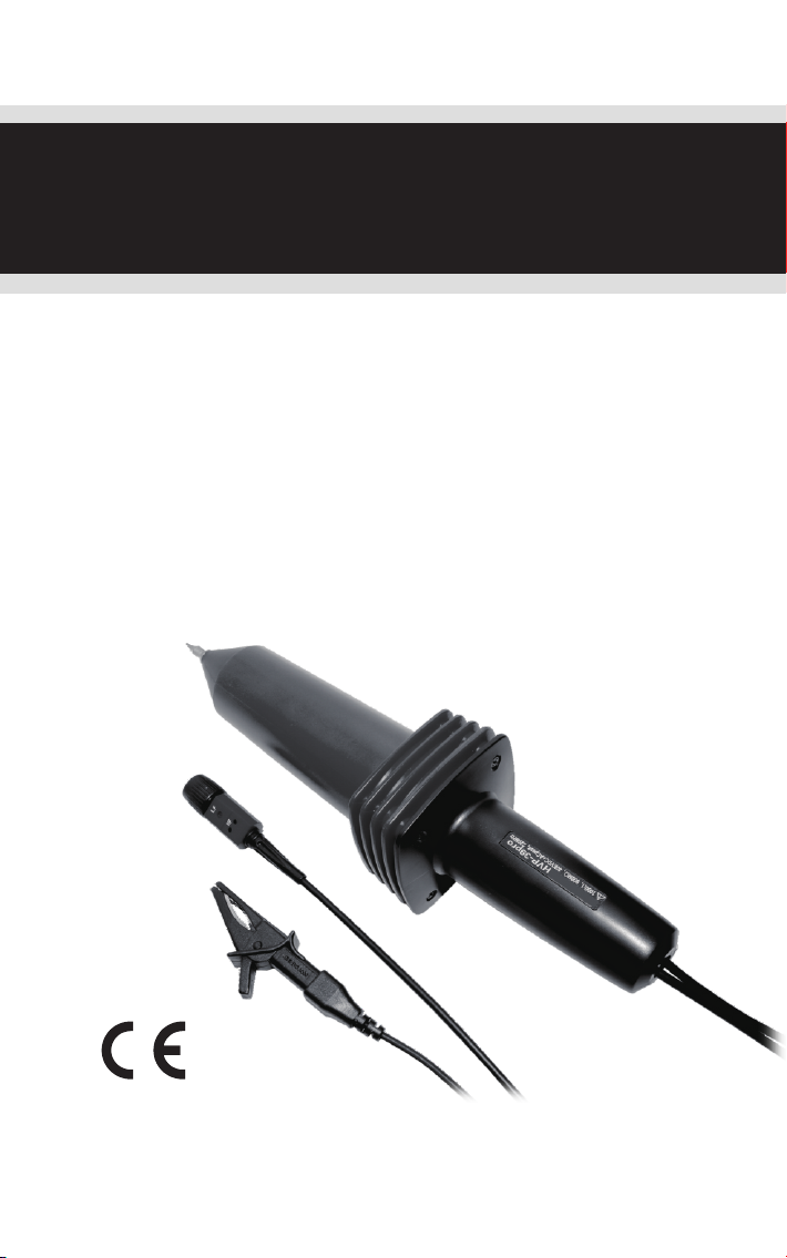
HIGH FREQUENCE HIGH VOLTAGE PROBE
INSTRUCTION MANUAL
For model:
HVP-10R / HVP-18HF /
HVP-28HF / HVP-39pro
使用說明書
高壓測試棒

1. SPECIFICATIONS
2. SAFETY PRECAUTIONS
3. OPERATION
4. COMPENSATION ADJUSTMENT
4-1 HVP-10R
4-2 HVP-18HF/ HVP-28HF/ HVP-39pro
5. WARNING
6. CLEANING
7. VOLTAGE DERATING CURVE
8. ACCESSORIES
1
2
2
3
3
4
6
6
TABLE OF CONTENTS
7
9
1. 規格
2. 簡述與安全須知
3. 操作說明
4. 匹配電容調整
4-1 HVP-10R
4-2 HVP-18HF/ HVP-28HF/ HVP-39pro
5. 注意事項
6. 清潔
7. 電壓測試臨界曲線
8. 附件
目 錄
11
12
12
13
13
14
16
16
17
19

HVP-10R / HVP-18HF /
HVP-28HF / HVP-39pro
HIGH FREQUENCE
HIGH VOLTAGE PROBE
INSTRUCTION MANUAL
Caution!
When measuring voltage source is over DC 30KV or AC 20KV, this probe
is not suitable for long time using. High voltage source will have sparks in
the air and cause high voltage source regular circuit does not have time
to respond. This will have pulse high voltage and which will cause this
probe over rating and damage the product.
HVP-39pro:
[note*]
*

High Frequence High Voltage Probe Instruction Manual
1
1.SPECIFICATIONS
Model
Division Ratio
Read Out
Input Resistance
Input Capacitor
Max. DC+AC peak
Max. AC RMS.
Band Width
Rise Time
Signal / Noise
DCV Accuracy
Temp. Coefficient
Cable Length
Operation Temp.
Storage Temp.
Color: Handel/Body
Weight / Volume
HVP-10R HVP-18HF HVP-28HF HVP-39pro
100:1 1000:1 1000:1 1000:1
100MΩ200MΩ500MΩ900MΩ
2.0 PF 1.5 PF 1.7 PF 2.0 PF
10KV CAT II 18KV CAT II 28KV CAT II 39KV CAT II
7KV CAT II 12KV CAT II 20KV CAT II 27KV CAT II
DC~120MHz DC~100MHz DC~75MHz DC~50MHz
3.0 nS 3.5 nS 5.3 nS 7 nS
>60dB at 1KHz ; >50dB at 1MHz
≦3% Full Range
≦3% at 1 KHz
≦200 PPM/℃
2M±0.2M
-20~70 ℃
ACV Accuracy
-10~55 ℃
Black/Milk Gray Black/Yallow Black/Dark Gray Black/Red
460g /80(W) x 80(H) X 320(L) mm
Max. Loading Current 100uA 90uA 56uA 45uA
Compensation Range 10PF~35PF
Safety Meets EN61010-031 CAT II
Humidity 85% RH or less(at 35℃)
≦3%
(0~35KV)
Pulse Voltage < 7KVp-p < 12KVp-p < 20KVp-p < 27KVp-p

2
High Frequence High Voltage Probe Instruction Manual
2.SAFETY PRECAUTIONS
This high voltage probe only for the person who are trained,
experienced, or otherwise qualified to recognize hazardous
situations and who trained in the safety precautions that necessary
to avoid possible injury when using such a device.
Do not work alone when working with high voltage circuits.
For your own safety, inspect the probes for cracks and frayed or
broken leads before each use. If defects are noted, DO NOT USE the
probe.
Hands, shoes, floor and work bench must be dry. Avoid making
measurements under humid, damp or other environmental
conditions that might affect the safety of the measurement situation.
If possible, always turn the high voltage source off before connection
or disconnection the probe.
The probe body should be kept clean and free of any conductive
contamination.
The probe is for indoor use only.
Note:
Please hold the handle when in use. Do not pull the wire.
Replacement or refund is not possible if the co-axis wire is broken
caused by the pulling of wire.
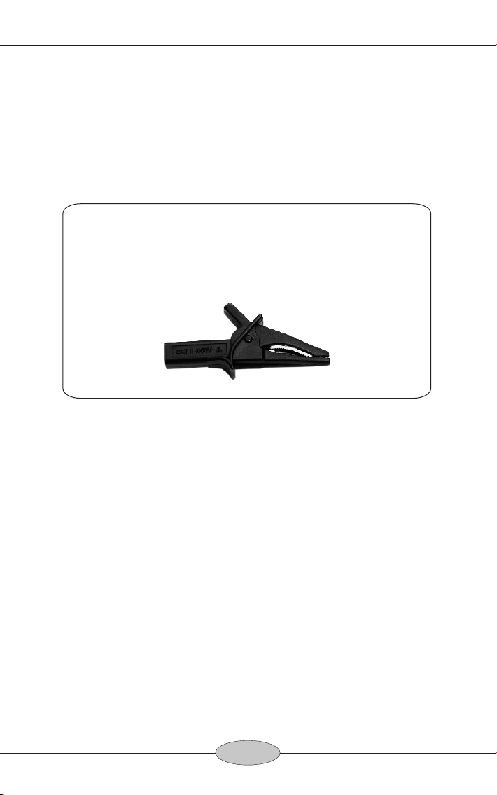
Connect the divider probe common lead(alligator clip) to a good
earth ground or reliable ground.
Connect the BNC connector to the BNC input of your oscilloscope.
Select the desired range of your oscilloscope. Whenever possible,
turn the high voltage source off before making any connections.
3.OPERATION
3
High Frequence High Voltage Probe Instruction Manual
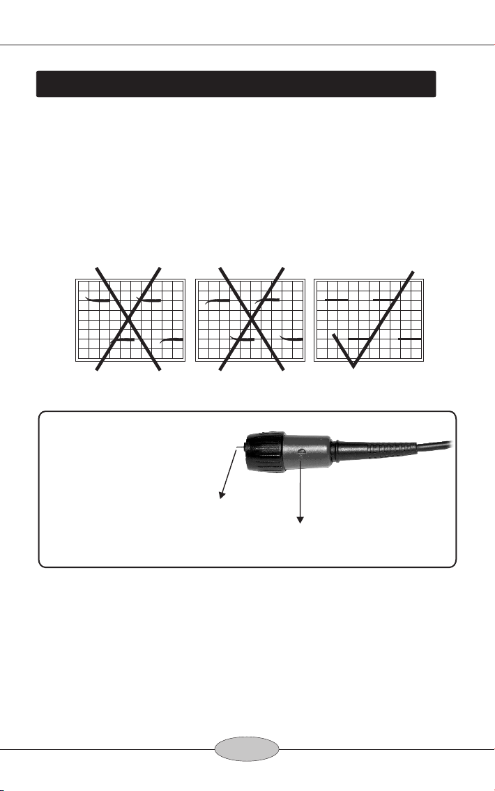
4.COMPENSATION ADJUSTMENT
4-1 HVP-10R:
The following adjustment is required whenever the probe is
transferred from one oscilloscope or input channel to another.
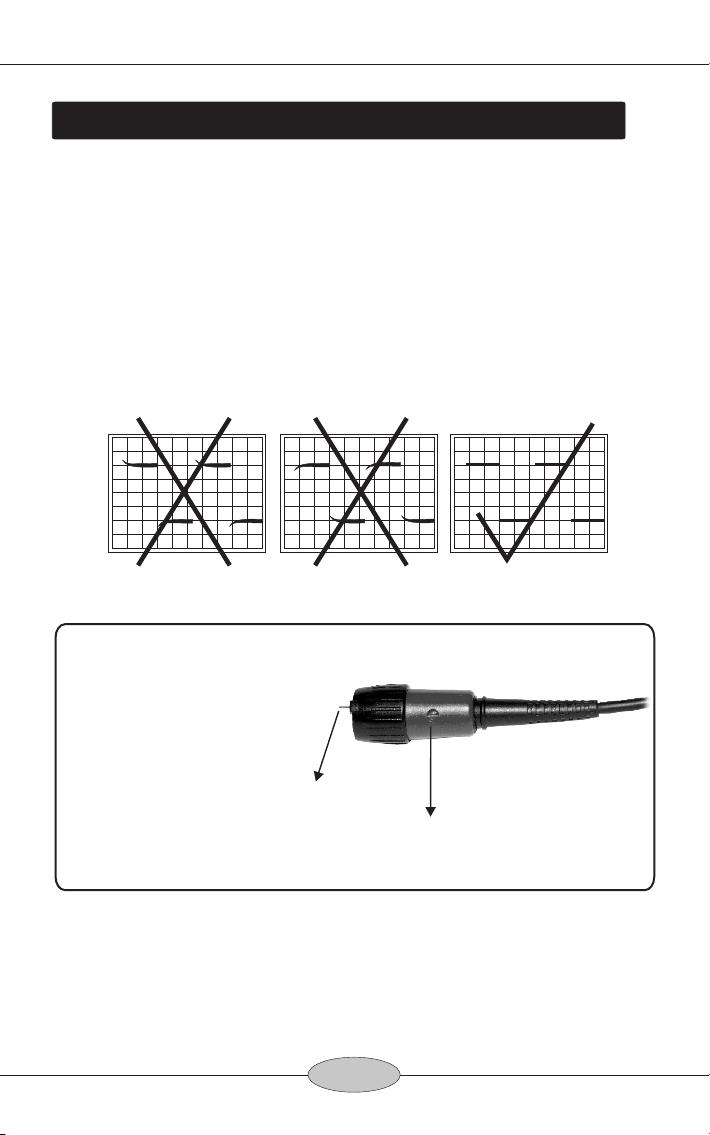
Connect the probe to the oscilloscope, apply a 1KHz square wave to
the probe tip and adjust the oscilloscope controls to display a few
cycles of the waveform. Adjust the trimmer located in the BNC plug
for a flat topped square wave.
ReadOut Pin
The HVP-10R is
compatible with
readout function
oscilloscopes that
automatically detect
and display the
attenuation factor of
the probe. for 1 KHz Adjustment
Hole 1.
Illustration of 1KHz square wave adjustment.
CAUTION:
When the measuring frequency was 40MHz up, you must change to
the shortest earth lead and connected to the Alligator Clip(BP-276N-
D) to obtained a best earth and the best frequency response.

4
High Frequence High Voltage Probe Instruction Manual
Adjust the frequency
response of the probe to
match your oscilloscope
by the adjust bar
attached only.
for 200Hz Square Wave Adjustment
for 200KHz Square Wave
Adjustment
for Bandwidth Adjustment
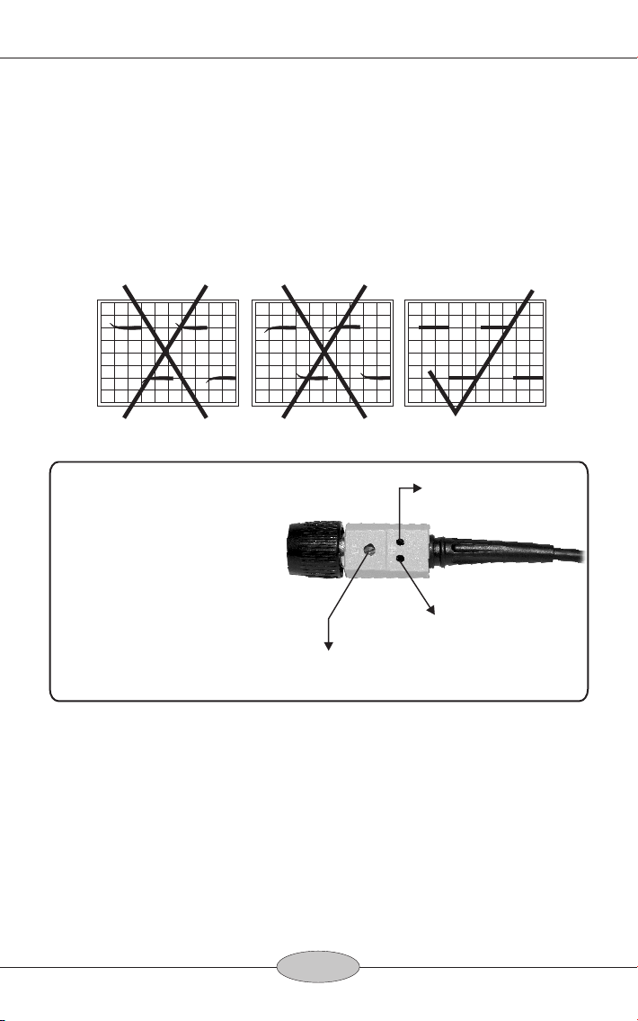
4-2 HVP-18HF/ HVP-28HF/ HVP-39pro:
The following adjustment is required whenever the probe is
transferred from one oscilloscope or input channel to another.
Connect the probe to the oscilloscope, apply a 200Hz square wave to
the probe tip and adjust the oscilloscope controls to display a few
cycles of the waveform. Adjust the trimmer located in the BNC plug
for a flat topped square wave.
Hole 1.
Hole 2.
Hole 3.
Illustration of 200Hz square wave adjustment.
CAUTION!
1. The HVP-18HF/ HVP-28HF/ HVP-39pro adjust Hole 2 and Hole 3
are for the qualified engineer only.
2. The HVP-10R adjusts Hole 1 only.

5
High Frequence High Voltage Probe Instruction Manual
3. Before adjusting Hole 2 and hole 3, please move off the plastic
cover at first.
4. Use the adjust bar attached only.
5. When the measuring frequency was 40MHz up, or to adjust
Bandwidth(Hole 3.), you must changed to the shortest earth lead
and connected to the Alligator Clip(BP-276N-D) to obtained a best
earth and thee best frequency response.
BP-276N-D
(For 40MHz up
Measuring Frequency)
6
High Frequence High Voltage Probe Instruction Manual
5.WARNING
6.CLEANING
Do not attempt to take measurements from the sources when the
chassis or return lead is not ground.
The ground connection is critical to the safety operation of the probe.
Failure to make this connection may result in personal injury or
damage to the probe or voltmeter. This connection must be made
before the probe tip comes into contact with the high voltage and
must not be removed until after the probe tip has been removed.
Do not connect the ground clip to the high voltage source or the
probe tip to the ground for any reason.
BEFORE turning the high voltage on, make sure that no part of your
body is in contact with the device.
Remembering that the voltage being measured is 1000 times(HVP-
10R is 100 times) greater than the voltmeter reading.
Disconnect the probe tip from the high voltage source BEFORE
removing the ground clip lead.
SPECIAL WARNING:
Please be sure the ground cable is connected securely. High voltage
may damage oscilloscopes if ground cable is not connected properly.
Clean only the exterior probe body and cables. Use a soft cotton cloth
lightly moistened with a mild solution of detergent and water. Do not
allow any portion of the probe to submerged at any time.
Dry the probe thoroughly before attempting to make voltage
measurement.
Do not subject the probe to solvents or solvent fumes as these can
case deterioration of the probe body and cables.
7
High Frequence High Voltage Probe Instruction Manual
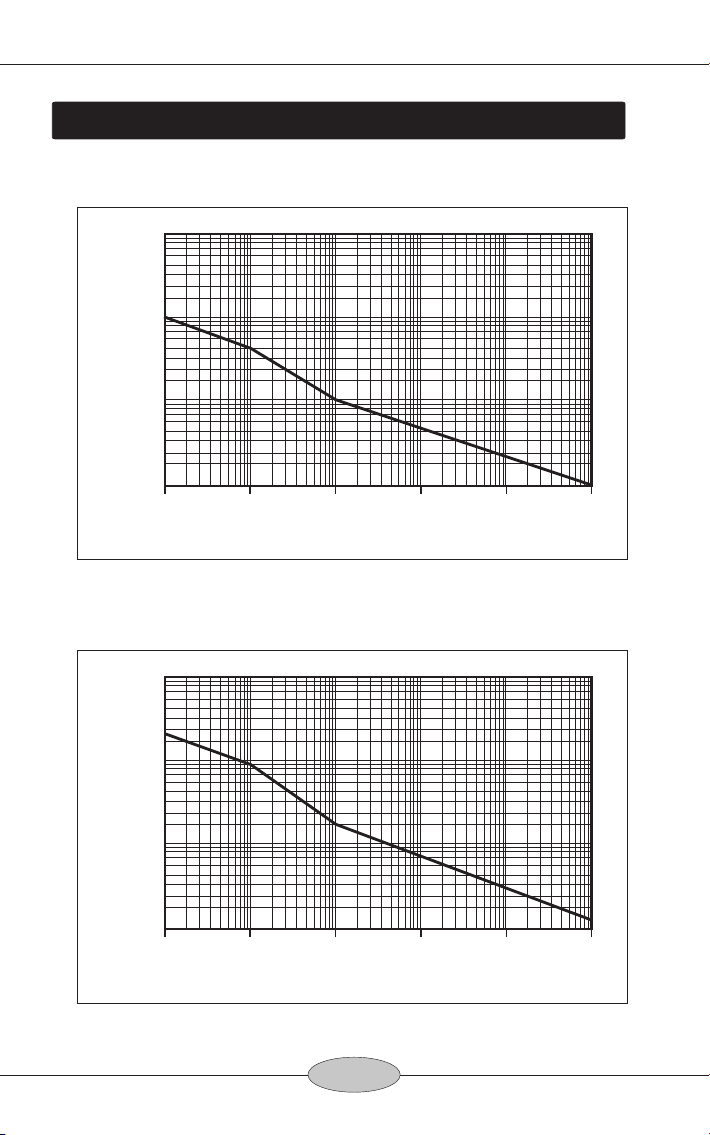
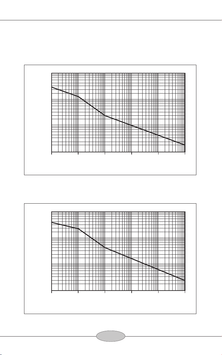
7.VOLTAGE DERATING CURVE
7-1 HVP-10R (10KV:1KHz /5KV:10KHz /1KV:100KHz /100V:100MHz)
7-2 HVP-18HF (18KV:1KHz /9KV:10KHz /2KV:100KHz /150V:100MHz)
Fig.1 Frequency
Voltage(DC+ACp-p)
100V
1KHz 10KHz 100KHz 1MHz 10MHz 100MHz
1KV
10KV
100KV
20KV
Fig.2 Frequency
Voltage(DC+ACp-p)
100V
1KHz 10KHz 100KHz 1MHz 10MHz 100MHz
1KV
10KV
100KV
20KV
(18KV)
8
High Frequence High Voltage Probe Instruction Manual
7-3 HVP-28HF (28KV:1KHz /14KV:10KHz /3KV:100KHz /200V:100MHz)
7-4 HVP-39pro (39KV:1KHz /20KV:10KHz /5KV:100Hz /300V:100MHz)
Fig.3 Frequency
Voltage(DC+ACp-p)
100V
1KHz 10KHz 100KHz 1MHz 10MHz 100MHz
1KV
10KV
100KV
20KV
(28KV)
Fig.4 Frequency
Voltage(DC+ACp-p)
100V
1KHz 10KHz 100KHz 1MHz 10MHz 100MHz
1KV
10KV
100KV
20KV
(39KV)
9
High Frequence High Voltage Probe Instruction Manual
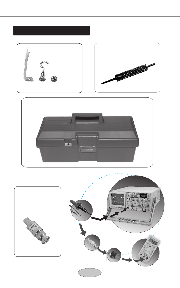
8.ACCESSORIES
PL-10(Option)
ROD-ADJ-002
Adjust bar
To Connect With
Digital DMM.
Test CRT
for H.V.
PX-503
Carry Box
Feed 10MΩ
Impedance
DMM
MT-246
PL-10
Oscillossope
High Voltage Probe

高壓測試棒使用說明書
HVP-10R / HVP-18HF /
HVP-28HF / HVP-39pro
注意! 當 測量電壓 源超過DC 30KV, 或AC 20KV以上時,
本產 品不適用 於長時間使用。 因 為高電壓 的測量來源將
會對 空氣中任 意放電, 造成高壓電 壓源的穩 壓電路來不及
反應, 瞬 間將會有 脈衝高 壓發生, 脈衝 高壓很有 可能超過
本產品的額定值, 將會造成本產 品的嚴重 損壞。
HVP-39pro:
[註*]
*

High Frequence High Voltage Probe Instruction Manual
11
1. 規 格
型號
衰減 比例
讀出 功能
輸入 阻抗
輸入 電容
最大輸入:DC+AC peak
最大輸入:AC RMS.
頻寬
上升 時間
噪信 比
直流 信號誤差 值
溫度 係數
測試 線長度
操作 溫度溼度
儲存 溫度
顏色:握 把/本體
重量/材 積
HVP-10R HVP-18HF HVP-28HF HVP-39pro
100:1 1000:1 1000:1 1000:1
100MΩ200MΩ500MΩ900MΩ
2.0 PF 1.5 PF 1.7 PF 2.0 PF
10KV CAT II 18KV CAT II 28KV CAT II 39KV CAT II
7KV CAT II 12KV CAT II 20KV CAT II 27KV CAT II
>60dB at 1KHz ; >50dB at 1MHz
≦3% 全部範 圍檔
≦3% 在 1 KHz
≦200 PPM/℃
2M±0.2M
-20~70 ℃
交流 信號誤差 值
-10~55 ℃/ 85% RH 或 更低(at 35℃)
黑/淺灰色
460g /80(寬) x 80(高) X 320(長) mm
最大 負載電流 100uA 90uA 56uA 45uA
匹配 電容調整範圍
10PF~35PF
安規 檢驗 符合 EN61010-031 CAT II 規 範
黑/黃色 黑/鐵灰色 黑/紅色
≦3%
(0~35KV)
脈波 電壓 < 7KVp-p < 12KVp-p < 20KVp-p < 27KVp-p
DC~120MHz DC~100MHz DC~75MHz DC~50MHz
3.0 nS 3.5 nS 5.3 nS 7 nS

High Frequence High Voltage Probe Instruction Manual
2. 簡 述與安 全 須知
感謝您購買HVP系列高壓 測 試 棒; 高壓測 試 棒是 為防 止測
試人員在做高壓測量工作時,受到意外電擊,而設計的
一種產品。在使用高壓測試棒以前,操作者必須先閱讀
安全規則並且充分理解後才能使用高壓測試棒。
此外, 只 有接 受過 高壓 測試培養訓練、有過高壓測試經 驗
或能辨別高壓危險情況的測試人員才能使用這種高壓測
試棒。在使用高壓測試棒的時候,受過安全警示知識培
養訓練的測試人員可以防止在操作過程中出現意外的傷
害。
請不要一個人在超過人體 安 全 範圍的電壓下工作。
為了自身的安全,每次使 用 高 壓測試棒以前,要認真檢
查所使用高壓棒表面磨損 和 高 壓棒測試端破損情況, 如果
有磨損、破損問題出現, 千 萬 不要使用此測試棒。
雙手、鞋、地板和工作椅 一 定 要保持乾燥, 並避免在潮
濕、發霉或者其他影響安全測量的環境下進行測量工
作。在連接或者拆下測試棒以前,需要把高壓電源關
閉。
高壓測試棒要保持乾淨, 污 垢 等沾染物能在測試棒表面
提供傳導途徑,一定要使 用 無 安全隱憂的測試棒。
注意:
使用時請握住把手,不要 拉 扯 電線,如拉扯電線造成鋅
線斷掉不于更換或退貨。
連 接 測 試 棒 衰 減 端 的 地 線 ( 鱷 魚 夾 ) 到 好 的 接 地 點 或 可
靠的接地測試端上。
連接BNC連接頭到示波器的BN C輸 入端 口。
選擇示波器要求的量程範圍。
[注意] 無論如何, 請務必在連接測試以前 把 高壓 電源關
閉。
3. 操 作說明
12
High Frequence High Voltage Probe Instruction Manual
4. 匹 配電容 調 整
4-1 HVP-10R:
每 當 測 試 棒 更 換 示 波 器 或 更 換 通 道 時,請 先 進 行 下 列 調 整
步驟:
連接測試棒至示波器, 輸入1KHz方波至測 試 棒測 試端, 然
後調整示波器控制項進而 顯 示 一些波形, 並 針 對方 波波 型
上升型態調整位於BNC接頭 的 可變電容器。
讀出針
HVP-10R 是有 讀 出
功能的; 當接在有
讀出功能的示波器
並正確的選擇衰減
比例, 就能自動讀
出原測試值電壓。
1KHz方 波調整點
Hole 1.
正確調整1KHz 方波的示意圖
警告:
(1)當測量 頻 率大 於40MHz時, 必須將長地 線 更換 為鱷 魚夾
(BP-276N-D)以便取得 最 小的 接地 電阻 值和更高的頻率
響應。
(2)調整方 波 時請 指定使用本公司的附件調棒。
(3)1KHz方波 請 使用 函數 信號 產生器, 輸出20Vp-p, 或是
選用本公司出品的FG-32/52/72/102等機種 。
13
High Frequence High Voltage Probe Instruction Manual
4-2 HVP-18HF/ HVP-28HF/ HVP-39pro:
連接測試棒至示波器, 輸入200Hz方波至測試棒測試端,
然後調整示波器控制項進 而 顯 示一些波形, 並 針對 方波 波
型上升型態調整位於BNC接頭 的可變電容器。
Hole 1.
Hole 2.
Hole 3.
200Hz方 波調整點
200KHz方波調整點
頻寬調整點
更換示波器時請依
指示調整Hole 1.即
可。
正確調整200Hz方波的示意圖
警告:
(1)200Hz方波請使用函數信號產 生 器, 輸 出20Vp-p, 或是
選用本公司出品的FG-32/52/72/102等機種 。
(2)非專業人員請勿調整Hole 2, Hole 3 調整點。
(3)本產品出場時已經對Hole 2, Hole 3調整過, 請安心操
作使用。
(4)調整時請使用本公 司 附 的指定調棒。
14
High Frequence High Voltage Probe Instruction Manual
(5)當待測高壓的頻率超過40MHz時, 為了取得更 好 的頻
率響應與更佳的接地, 請將長 地 線 更換 為鱷魚夾(BP-
276N-D)。
BP-276N-D
(當量測 40MHz 以上的 高 頻 電壓時請改用此
鱷魚夾直接接地, 可以獲得更 佳 的 頻率 響應)
15

High Frequence High Voltage Probe Instruction Manual
5. 注 意事項
6. 清 潔
請勿試圖把測試設備的接 地 線 從地面接線柱上移開。
接 地 連 接 是 測 試 棒 安 全 操 作 的 一 個 關 鍵 點 。 當 高 壓 測 量
的 時 候 , 如 果 沒 有 這 種 連 接 將 可 能 導 致 人 身 傷 害 或 者 對
連 結 的 示 波 器 、 測 試 棒 產 生 損 害 。 在 測 試 棒 測 試 端 測 試
連 接 高 壓 前 , 一 定 要 先 連 接 好 地 線 , 並 且 地 線 連 接 不 能
輕易挪開,直到高壓測試 端 遠 離高壓源。
絕 對 不 能 把 接 地 線 與 高 壓 電 源 連 接 或 者 把 測 試 棒 測 試 端
接地。
打 開 高 壓 源 以 前 要 保 證 身 體 的 任 何 部 位 都 沒 有 和 測 試 設
備接觸。
測量電壓時,請牢記被測電壓是實際讀數的1000倍 。
在 移 走 接 地 夾 以 前 一 定 要 把 測 試 棒 高 壓 測 試 端 從 高 壓 源
上斷開。
特別注意!
接地線若接地不確實, 高壓電有可能擊 毀 示波 器, 請務必
接妥。
只 需 清 洗 測 試 棒 外 部 和 電 纜 即 可 , 用 軟 棉 布 輕 輕 蘸 點 酒
精和水清洗。不可以把測試棒的任何部分浸泡在液體
裡。
在做電壓測量以前要使測 試 棒 全部乾燥。
不 要 把 測 試 棒 放 進 有 腐 蝕 性 溶 液 或 者 有 腐 蝕 性 煙 氣 裡 ,
因為這樣將可能引起測試 棒 和 電纜的破損。
16

High Frequence High Voltage Probe Instruction Manual
7.電 壓測試 臨 界曲 線
圖.1
電壓(直流+交流峰值)
圖.2
電壓(直流+交流峰值)
17
頻率
頻率
7-1 HVP-10R
7-2 HVP-18HF
(10KV:1KHz /5KV:10KHz /1KV:100KHz /100V:100MHz)
(18KV:1KHz /9KV:10KHz /2KV:100KHz /150V:100MHz)
100V
1KHz 10KHz 100KHz 1MHz 10MHz 100MHz
1KV
10KV
100KV
20KV
100V
1KHz 10KHz 100KHz 1MHz 10MHz 100MHz
1KV
10KV
100KV
20KV
(18KV)
This manual suits for next models
3
Table of contents
Other Pintek Measuring Instrument manuals

Pintek
Pintek DP-16VF User manual

Pintek
Pintek DP-65 pro User manual

Pintek
Pintek PA-629 User manual

Pintek
Pintek DP-35 User manual

Pintek
Pintek PA-659 User manual

Pintek
Pintek DP-60HS User manual

Pintek
Pintek HVP-40 User manual

Pintek
Pintek DP-800HS User manual

Pintek
Pintek PA-622 User manual

Pintek
Pintek DP-5205A User manual


