Spectrum Brands 72A-190BQREM Series User manual

72A-196BAREM Series
72A-190BQREM Series
Installation and Operation
Manual
3-Phase Power Monitoring and
Distribution Unit
June 2, 2008
Rev-01
27-0027-0111

Installation and Operation Manual
SCI P/N: 72A-196BAREM Series
72A-190BQREM Series Date: 6/02/2008 2
27-0027-0111
Contents
Introduction & Safety Information ..............................................3
Technical Specications..............................................................4
Declaration of Conformity................................................................. 5
Connections and Installation
Operating Environment ............................................................... 6
Electrical Connections ................................................................. 7
Input and Output Connections..................................................... 7
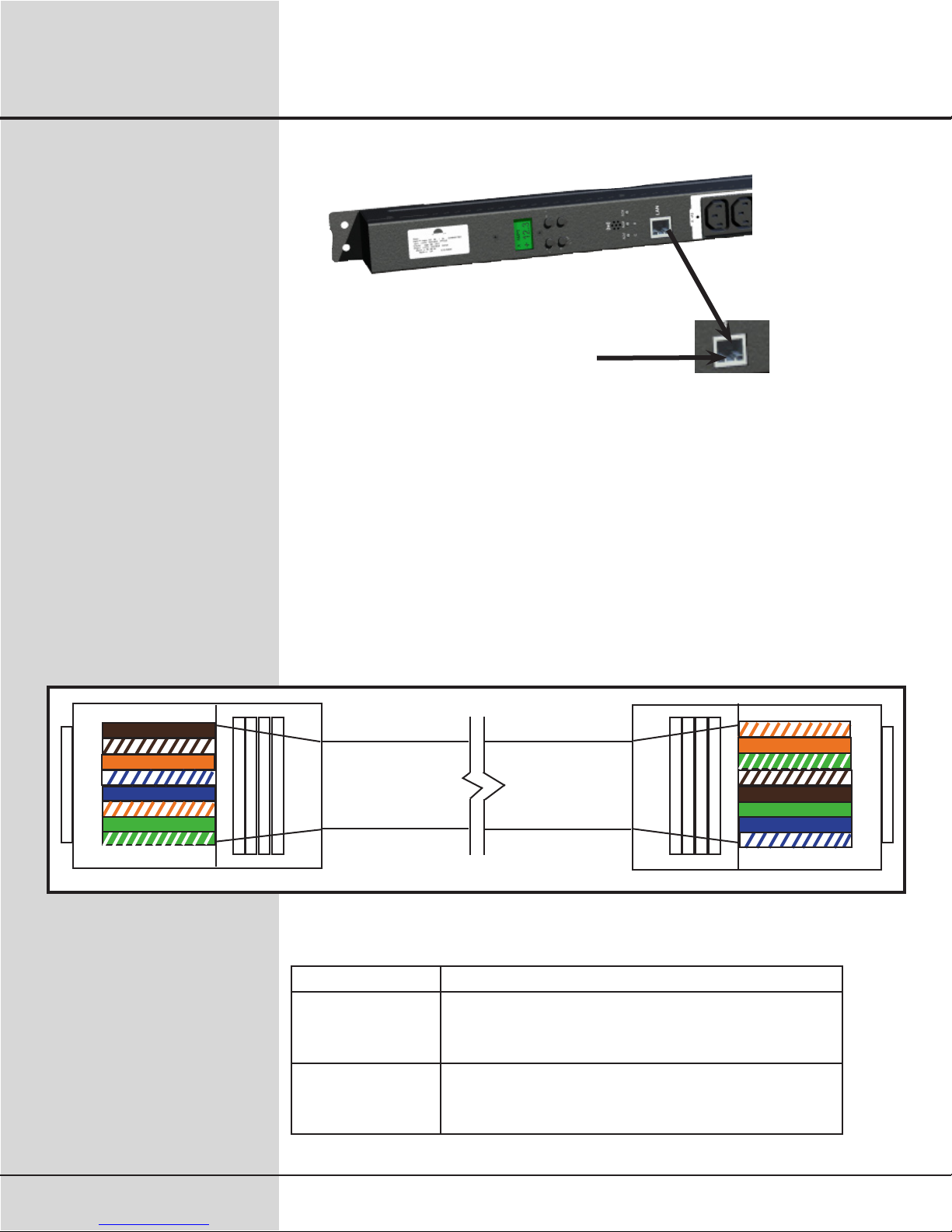
LAN Module and Communications .............................................. 8
LAN Module Interface.................................................................. 8
LAN LED Status Guide................................................................ 8
LAN Module IP Address, DHCP, and Auto IP .............................. 9
Device Discovery....................................................................... 10
TestingtheIPAddressConguration ........................................ 11
TelnetCongurationPassword.................................................. 11
LANModuleCongurationUsingaTelnetConnection ............. 11
Set PDU and LAN Module to Factory Defaults.......................... 12
ExitCongurationMode ............................................................ 13
LANModuleReashInstructions .............................................. 13
Operational Control of PDU
Front Panel Menu ...................................................................... 14
Menu Navigation........................................................................ 14
Alarm Capabilities...................................................................... 16
Networking Functions
Introduction................................................................................ 17
Telnet Communication ............................................................... 17
Telnet Commands...................................................................... 18
Simple Network Management Protocol (SNMP) ....................... 20
Accessing the SNMP Interface.................................................. 21
Key SNMP Settings ................................................................... 22
SNMP Security .......................................................................... 22
SNMP MAX and MIN Data ........................................................ 22
SNMP v2 Functions................................................................... 23
General MIB Usage ................................................................... 24
MIB Use With Vista Infrastructure Monitoring............................ 24
Maintenance & Warranty............................................................25
PDU Front Panel .........................................................................26

Installation and Operation Manual
Date: 6/02/2008 3
27-0027-0111
SCI P/N: 72A-196BAREM Series
72A-190BQREM Series
Introduction & Safety Information
The Spectrum Control PDU is an AC power distribution unit designed to
distribute power for up to eighteen (18) AC loads. The PDU distributes 3
phase power to six individual, over current protected, output banks. The
unit has multiple alarm capabilities and includes an audible alarm circuit.
Voltage and current are monitored and displayed locally on a liquid crys-
tal display and remotely through a LAN connection. Operation/control is
accomplished by use of 16A breaker actuators.
This product complies with FCC, CE, TUV, UL60950-1 and IEC60950
requirements.
Introduction
LCD – Liquid Crystal Display
LED – Light Emitting Diode
LL – Lower Limit
PDU – Power Distribution Unit.
BANK – Any power source entering a PDU that is then distributed to an
output.
UL – Upper Limit
Related Terms
This installation and operation manual contains information about the
Power Distribution Unit and basic installation instructions. The person
installing or integrating the PDU into an electronic system must be sup-
plied with this manual and read it to become familiar with the installation
precautions. Spectrum Control, Inc. cannot be held liable for any dam-
age to persons or property if the safety information in the installation and
operation manual is not followed.
If the safety information is not observed, personnel could be put at risk.
Only authorized personnel who have been properly trained may operate
the device. There are no user serviceable parts inside. Therefore, any
modicationsmadetotheunitbyanyorganizationorpersonsotherthan
the factory are not permitted.
The general regulations governing the use of electricity in the country in
which the device or integrated system is installed must be observed.
Safety Information
Manual Conventions
Symbol Action Example
< > Click on the items contained within these symbols
with your mouse.
<Start>
[ ] Press all keys that are contained within these brack-
ets.
[Ctrl]
“ ” Type all characters that are placed between quota-
tions
“1234”
The following actions should be taken when these symbols are present in
various instructions throughout the manual:

Installation and Operation Manual
SCI P/N: 72A-196BAREM Series
72A-190BQREM Series Date: 6/02/2008 4
27-0027-0111
TechnicalSpecications
Global Domestic
Power Entry
Connector
IEC 309, 4pole, 5 wire, 32A,
WYE connected
NEMA L21-30P
5 pin, Delta connected
Nominal Input
Voltage
3 ∅ 400/230VAC ±10% 3 ∅208/208VAC ±10%
Input Frequency 50 – 60 Hz 50 – 60 Hz
Input Current 72A maximum 41.6A maximum
Input
Output Global Domestic
Outlet Connectors (18) IEC C13 (18) IEC C13
Load Current per
Bank
16A maximum 13.9A maximum
Load Current per
Output Connector
10A maximum 10A maximum
Load Current per
PDU
72A maximum 41.6A maximum
Environmental • Operating temperature: 0-55°C (32-131°F)
• Operating humidity: 0-95% (non condensing)
• Operating elevation: 0-10,000 ft (0-3000 m)
Physical • Unit height: 0U, 55.5 inches (141 cm)
• Unit width: 1.75 inches (4.45 cm)
• Unit depth: 5.2 inches (13.3 cm)
Unit weight: 32.5 pounds (14.74 kg)
• Cord length: 10 feet (Approx. 3 m)
• Rack mountable
• Finish: Black powder coat
•

Installation and Operation Manual
Date: 6/02/2008 5
27-0027-0111
SCI P/N: 72A-196BAREM Series
72A-190BQREM Series
Declaration of Conformity
Manufacturer’s Name:
Manufacturer’s Address:
Declares that the product:
EMC:
Safety:
ConformstothefollowingProductSpecications:
Model Number:
Product Name:
Spectrum Power Management Systems, a Spectrum
Control Business
1900 West College Avenue
State College, PA 16801
3-Phase Power Monitoring and Distribution Unit
72A-196BAREM-01
72A-190BQREM-01
UL 60950-1 File E149758-A8 Volume X3, First Edition;
CSA C22.2 No. 60950-1-03, First Edition; IEC 60950-
1, First Edition.
Product Category: NWGQ-INFORMATION TECH-
NOLOGY EQUIPMENT INCLUDING ELECTRICAL
BUSINESS EQUIPMENT - COMPONENT
Quality Engineer
Emissions per:
EN 55022 (1998): Class A
FCC P.15
ANSI C63.4
Immunity per :
EN 55024
EN 61000-4-2: Criteria B
EN 61000-4-3: Criteria A (@ 10V/m)
EN 61000-4-4: Criteria B
EN 61000-4-5: Criteria B
EN 61000-4-6: Criteria A (Power @ 10V/m)
Lead Engineer
Spectrum Control, Inc.
Power Management Systems
1900 West College Avenue
State College, PA 16801
814-272-2700
11/16/2007
Chuck Drew Mike Esposit

Installation and Operation Manual
SCI P/N: 72A-196BAREM Series
72A-190BQREM Series Date: 6/02/2008 6
27-0027-0111
Connections and Installation
Operating
Environment
• Locate PDU in dry area.
• Rack Mount in equipment rack using mounting brackets.
• Restricted Access Location not required.
• This PDU relies on protective devices in the building installation
for short circuit and over current protection.
• Elevated Operating Ambient- If installed in a closed or multi-unit
rack assembly, the operating ambient temperature of the rack
environment may be greater than room ambient. Therefore,
consideration should be given to installing the equipment in an
environment compatible with the maximum ratings of the product.
• Reduced Air Flow- Installation of the equipment should be such
thattheamountofairowrequiredforsafeoperationofthe
equipment is not compromised.
• Mechanical Loading- Mounting of the equipment in the rack should
be such that a hazardous condition is not achieved due to uneven
mechanical loading.
• Circuit Overloading- Consideration should be given to the
connection of the equipment to the supply circuit and the effect
that overloading the circuits might have on over current protection
and supply wiring. Appropriate consideration of equipment
nameplate ratings should be used when addressing this concern.
• Reliable earthing of equipment should be maintained. Particular
attention should be given to supply connections other than direct
connections to the branch circuit (e.g. use of power strips).
Consult the local electrical code for additional information.

Installation and Operation Manual
Date: 6/02/2008 7
27-0027-0111
SCI P/N: 72A-196BAREM Series
72A-190BQREM Series
Electrical
Connections
• Depress rocker handle of all circuit breakers to “off” position.
Example: Breaker Off Example: Breaker On
• Connect input supply cord to a grounded power source rated for
the input voltage and current of the PDU.
• Connect equipment to AC output connectors. Continuous
current draw for all connected units must not exceed the current
rating per output.
Power source for PDU must be properly grounded.
Total current for all connected units must not exceed the
current rating per input.
Current must not exceed the current rating per output.
Do not conduct any DWV testing greater than 300 VAC.
•
•
•
•
CAUTION:
Input and Output
Connections
Input cord and output connections are located on the front side of the
unit. Pluggable mating connectors are not supplied with the unit.
Connections and Installation

Installation and Operation Manual
SCI P/N: 72A-196BAREM Series
72A-190BQREM Series Date: 6/02/2008 8
27-0027-0111
LAN Module and
Communications
RJ45
LAN Connection
LAN Module
Interface
The LAN Module provides an interface between a computer
network and the power distribution unit using the front RJ-45 jack.
Communications between the PDU and a computer can take place via a
Telnet session or SNMP manager. If you are connecting the PDU directly
to a PC without a router, a crossover cable is required. The module oper-
ates at 10/100MB/sec via an Ethernet communication for both of these
congurationsandusesaRJ45connectorfortheinterfacejack.
Connections and Installation
LAN LED Status
Guide
LED Description
Top left
(Yellow)
Network link status:
Off - no link has been detected.
On - a link has been detected.
Top right
(Green)
Serial port activity/Network activity:
Off - the serial channel is idle.
Blinking - serial data is transmitted or received.
8
7
6
5
4
3
2
1
1
2
3
4
5
6
7
8
Crossover Cable

Installation and Operation Manual
Date: 6/02/2008 9
27-0027-0111
SCI P/N: 72A-196BAREM Series
72A-190BQREM Series
The LAN module consists of integrated hardware and a network agent
softwareprogram.Thesecomponentsprovidetheabilitytocongure,
control, and monitor aspects of multiple units using a standard web
browser. The network interface can operate using Telnet and SNMP.
TheLANmoduleisconguredatthefactorytoanIPAddressof
192.168.1.110 and subnet mask of 255.255.255.0. A default gateway ad-
dress of 192.168.1.1 and a SNMP trap address of 192.168.1.200 are also
provided.
The Login dialog box requests a username and password. The factory
default username and password are “root” and “1234”, respectively. This
username has full privileges to set up, maintain, and control the unit.
LAN Module IP
Address, DHCP, and
Auto IP
Connections and Installation
The LAN module supports three IP assignment methods: Static IP ad-
dress, DHCP, and Auto-IP. If a static address is enabled, it will be used.
If a static address is not enabled, and Auto-IP is enabled, it will be used
to generate an address ONLY if DHCP is disabled, or if DHCP is enabled
and a DHCP server has not responded to the DHCP query. If both are
enabled, Auto-IP has assigned an address, and then a DHCP server
responds. The Auto-IP address will be discarded and the DHCP address
will be used.
Other Factory Defaults:
SNMP Enabled
SNMP Community Name Public
Telnet Setup Enabled
FTP Download Enabled
Web Server Disabled - Can enable with
future Firmware Update
Web Setup Disabled
ECHO Disabled
AutoIP allows the unit to obtain an address in a network that does not
have a DHCP server. AutoIP assigns a random valid address to the LAN
module in the range of 169.254.x.x to 169.254.x.x where x is between 0
and 255 and a Netmask of 255.255.0.0.

Installation and Operation Manual
SCI P/N: 72A-196BAREM Series
72A-190BQREM Series Date: 6/02/2008 10
27-0027-0111
Connections and Installation
The discovery tool “digi_dev_disc.exe” has the following:
1.“CongureNetworkSettings”istoconguretheIP/Subnet/Gateway.
2. “Restart Device” is to reboot the PDU after assigning the new network
conguration.
3. “Refresh View” is to search again.
4. “Open Web Interface” is to launch the web page.
This program is part of the PDU tools and should be placed in
C:\Program Files
Device Discovery

Installation and Operation Manual
Date: 6/02/2008 11
27-0027-0111
SCI P/N: 72A-196BAREM Series
72A-190BQREM Series
Connections and Installation
Telnet Conguration
Password
SettingtheTelnetcongurationpasswordpreventsunauthorizedaccess
of the setup menu via a Telnet connection to port 9999. The password
is limited to 32 characters. Option 7 allows the user to change the telnet
congurationpassword.
Testing the IP
Address
Conguration
Once the IP address is assigned, you should test the IP address
congurationtobesureitworksascongured.
Prerequisite
Thisprocedureassumesthatyouhaveconguredthedeviceserverwith
an IP address.
Procedure
1. Access the command line of a PC or other networked device.
2. Issue the following command: ping ip-address (where ip-address
is the address you assigned to the device server).
Example:
ping 192.168.1.110
A reply should be returned.
LAN Module
Conguration Using
a Telnet Connection
ToconguretheLANModuleoverthenetwork,establishaTelnet
connection to port 9999. From the Windows Start menu, click Run and
type the following command, where x.x.x.x is the IP address and 9999 is
theLANModule’sxednetworkcongurationportnumber.
telnet x.x.x.x 9999
Note: Be sure to include a space between the IP address and 9999.
The default IP Address is 192.168.1.110, so the command should look
like “telnet 192.168.1.110 9999”. At login, type “root” for the username
and“1234”forthepassword.Thiscommandwilllaunchtheconguration
menu.Aftertherstsentenceappears,press[Enter]togointothesetup
mode.

Installation and Operation Manual
SCI P/N: 72A-196BAREM Series
72A-190BQREM Series Date: 6/02/2008 12
27-0027-0111
Connections and Installation
Set PDU and LAN
Module to Factory
Defaults
Menu option 8 restores all PDU and LAN module defaults back to the
factory settings. This command will ensure that both the LAN module
and internal PDU microprocessor are returned to identical
communicationsettings.PDUwithLANmodulesshouldhaveallcongu-
rationchangesmadeusingtheLANmodulecongurationmenuselec-
tions.
Items that get restored back to default settings:
snmpReadCommunityName
snmpRead-WriteCommunityName
SNMP TRAP_IP
TRAPDSTPORT
HTTPPORT
USER NAME
PASSWORD
•
•
•
•
•
•
•

Installation and Operation Manual
Date: 6/02/2008 13
27-0027-0111
SCI P/N: 72A-196BAREM Series
72A-190BQREM Series
Connections and Installation
Exit Conguration
Mode
Select9toexitthecongurationmodewithoutsavinganychanges,or
select 10 to exit and save all changes. All values are stored in
nonvolatile RAM. The LAN Module will automatically reset, but the state
of the PDU outputs will not be affected.
Run “digi_dev_disc.exe” utility to set up unit’s IP, if necessary. These are
part of the LAN tools.
Locatetheupdatele.
A. If any network setting(s) on the LAN module are changed, you
must click <Restart device> to apply the changes.
B. Placetheupdatele“image.bin”inC:\release.
C. In command window, navigate to C:\release directory.
Type “ftp <IP Address>”.
D. Then log-in (User name is “root”, and password default is “1234”.)
E. Type “binary” and press [Enter].
F. Type “put image.bin” and press [Enter]. **Wait for the
completion message** Do not interrupt download.
G. Type “quit” after the “Transfer Complete” message appears. It may
take up to 1 minute, including PDU reboot.
H. In “C:\release\bin”, type “ping <IP Address> -t” until the
communication is re-established. Press [Ctrl+C] to exit ping.
LAN Module Reash
Instructions

Installation and Operation Manual
SCI P/N: 72A-196BAREM Series
72A-190BQREM Series Date: 6/02/2008 14
27-0027-0111
Operational Control of PDU
Front Panel Menu Theunit’sLCDisusedtomonitorincomingpowerandcongurethe
software. The LCD has two modes of operation: Monitor or Menu. The
system menu is organized in a top down tree structure. The unit has
four buttons that are used to navigate through the menu system. The
buttons are labeled with universal symbols for Menu, Select, Left, and
Rightasshowninthefollowinggure.
MENU - Enters the menu system or moves one level up the tree.
SELECT - Moves one level down the tree or accepts a parameter input.
LEFT, RIGHT - Moves horizontally through menu items or parameters.
Alarm Acknowledgment – Silences audible alarm.
Menu Navigation Selecting the MENU button while the unit is in monitor mode will bring
up the system top level menu. The top level menu contains parameters
for Alarm Acknowledgement, Incoming Power Peak Readings, Incoming
PowerLimitSettings,andSystemConguration.

Installation and Operation Manual
Date: 6/02/2008 15
27-0027-0111
SCI P/N: 72A-196BAREM Series
72A-190BQREM Series
Operational Control of PDU
PEAKS - MAX, MIN, RESET
Selecting PEAKS in the menu system allows the user to view the
maximum and minimum values that have been recorded for both voltage
and current for each distribution bank. This feature also gives the user
the option to reset these values.
LIMITS - MAX, MIN
Selecting LIMITS in the menu system allows the user to set the desired
maximum and minimum values to monitor for each bank. These values
will be used by the unit as comparison limits while monitoring bank
voltage and current levels. Decisions concerning minor and major
alarms will be based on this comparison.
CONFIG - DISPLAY MODE
While in Monitor Mode, the unit can display the incoming voltage and
current readings. The menu system allows the user to select one of
three display modes: CYCLE, FIXED, and BAR.
Selecting CYCLE causes the system to cycle the display of channel
measurements. Measurements will be shown in order of voltage
channels and then current banks.
Selecting FIXED turns off the measurement display cycle. Pressing the
LEFT or RIGHT menu buttons while in FIXED mode moves to the next
reading in the cycle list.
In BAR mode, a bar graph is displayed to show all measured bank
currents at the same time. The values are displayed on a 30 amp scale.
Minimum Current Channel A
Maximum Current Channel A
Minimum Current Channel B
Maximum Current Channel B
Minimum Current Channel C
Maximum Current Channel C
Minimum Current All Channel Total
Maximum Current All Channel Total
Minimum Voltage Channel A
Maximum Voltage Channel A
Minimum Voltage Channel B
Maximum Voltage Channel B
Minimum Voltage Channel C
Maximum Voltage Channel C
Reset All Peaks
Minimum Current Channel A
Maximum Current Channel A
Minimum Current Channel B
Maximum Current Channel B
Minimum Current Channel C
Maximum Current Channel C
Minimum Current All Channel Total
Maximum Current All Channel Total
Minimum Voltage Channel A
Maximum Voltage Channel A
Minimum Voltage Channel B
Maximum Voltage Channel B
Minimum Voltage Channel C
Maximum Voltage Channel C
Monitor Display Mode
Display Cycle time
Voltage Calibration Step 1 Chan A
Voltage Calibration Step 2 Chan A
Voltage Calibration Step 1 Chan B
Voltage Calibration Step 2 Chan B
Voltage Calibration Step 1 Chan C
Voltage Calibration Step 2 Chan C
Current Calibration Step 1 Chan A
Current Calibration Step 2 Chan A
Current Calibration Step 1 Chan B
Current Calibration Step 2 Chan B
Current Calibration Step 1 Chan C
Current Calibration Step 2 Chan C
Number of Channels
Contrast
Software Rev
Menu Tree
Alarm Acknowledgment Incoming Power Peaks Incoming Power Limits SystemConguration
None

Installation and Operation Manual
SCI P/N: 72A-196BAREM Series
72A-190BQREM Series Date: 6/02/2008 16
27-0027-0111
CONFIG - CYCLE TIME
The CYCLE TIME parameter sets the amount of time to wait before
displaying the next bank measurement. The parameter can be set to
FAST, MEDIUM, or SLOW.
CONFIG - NUMBER OF CHANNELS
Theunitcanbeconguredtoworkfor1,2,or3powerbankdevices.
Note that reducing the number of banks to 1 removes the total current
monitoring processes.
CONFIG - CONTRAST
The CONTRAST feature allows the user to adjust the contrast of the LCD
screen to a desired level.
CONFIG – SOFTWARE REV
Selecting the REV parameter will display the current revision of software
loaded into the meter.
CONFIG - METERING CALIBRATIONS
The unit’s onboard voltage and current monitoring devices require a
two-step calibration procedure to achieve maximum accuracy. Each
power bank has adjustable parameters in the menu system for voltage
and current. This calibration is performed at the factory before shipment.
Operational Control of PDU
Alarm Capabilities Each power bank has four major alarm thresholds that can be adjusted.
There is an upper and lower limit for input voltage. There is also an
upper and lower limit for distributed current. An alarm is also signaled
if the current reaches two minor limits: 80% of upper limit, 90% of upper
limits.
If a major alarm threshold is surpassed the unit will respond by setting
the power bank indicator LED to red and setting the audible alarm
buzzer.
If a minor alarm threshold is surpassed the unit will toggle the LED
indicator and audible alarm. The 80% alarm toggles the LED and buzzer
once per second. The 90% alarm toggles twice per second.
If an alarm condition exists and the PDU is in monitor mode, the audible
alarm may be silenced by pressing the Alarm Acknowledge button. If the
PDU is not in monitor mode and is in the system menu, select the Alarm
Acknowledge menu item. The audible alarm will remain silenced until
another alarm threshold is exceeded.

Installation and Operation Manual
Date: 6/02/2008 17
27-0027-0111
SCI P/N: 72A-196BAREM Series
72A-190BQREM Series
Networking Functions
The PDU LAN Port supports the Telnet and SNMP networking functions,
which allow remote monitoring through the network environment. Table
1 lists the available Telnet commands. Table 2 lists the content of SNMP
functions – Read/Set/Trap in detail. An SNMP Manager PC Tool is need-
ed in order to implement the SNMP functions. To implement the Telnet
andSNMPfunctions,thedevicemustbeconguredproperly,suchas
assigning a valid IP address or subnet mask by using the recommended
device discovery tool.
Telnet always has the higher priority than SNMP with the timeout value of
30 seconds, which can be adjusted later.
Introduction
Telnet
Communication
You can access the PDU by typing “telnet <IP> 10001” and entering the
username and password (Default username is “root”. Default password is
“1234”). The telnet session has a 30 second timeout.
A list of commands is in the following table.

Installation and Operation Manual
SCI P/N: 72A-196BAREM Series
72A-190BQREM Series Date: 6/02/2008 18
27-0027-0111
telnet <IP Address> 10001 [space before and after address]
Table 1
List of Commands:
Command Description Response
@AACK Alarm Acknowledgement #AACK
@SYSF Save settings to EEPROM #SYSF OK
@BNKV A,? Voltage Bank A #BNKV 120.2
@BNKV B,? Voltage Bank B #BNKV 120.2
@BNKV C,? Voltage Bank C #BNKV 120.2
@BNKC A,? Current Bank A #BNKC 22.5
@BNKC B,? Current Bank B #BNKC 22.5
@BNKC C,? Current Bank C #BNKC 22.5
@BNKC T,? Total Current on PDU (All banks) #BNKC 65.3
@MAXV A,? Read Maximum Voltage Bank A #MAXV 138
@MAXV B,? Read Maximum Voltage Bank B #MAXV 138
@MAXV C,? Read Maximum Voltage Bank C #MAXV 138
@MINV A,? Read Minimum Voltage Bank A #MINV 75.0
@MINV B,? Read Minimum Voltage Bank B #MINV 75.0
@MINV C,? Read Minimum Voltage Bank C #MINV 75.0
@MAXV A,0 Reset Maximum Voltage Bank A #MAXV OK
@MAXV B,0 Reset Maximum Voltage Bank B #MAXV OK
@MAXV C,0 Reset Maximum Voltage Bank C #MAXV OK
@MINV A,999.9 Reset Minimum Voltage Bank A #MINV OK
@MINV B,999.9 Reset Minimum Voltage Bank B #MINV OK
@MINV C,999.9 Reset Minimum Voltage Bank C #MINV OK
@BULV A,135.3 Set High Threshold Voltage Bank A #BULV OK
@BULV B,135.3 Set High Threshold Voltage Bank B #BULV OK
@BULV C,135.3 Set High Threshold Voltage Bank C #BULV OK
@BULC A,22.5 Set High Threshold Current Bank A #BULC OK
@BULC B,22.5 Set High Threshold Current Bank B #BULC OK
@BULC C,22.5 Set High Threshold Current Bank C #BULC OK
@BULC T,77.5 Set High Threshold Current Bank T #BULC OK
@BLLC A,10.0 Set Low Threshold Current Bank A #BLLC OK
@BLLC B,10.0 Set Low Threshold Current Bank B #BLLC OK
@BLLC C,10.0 Set Low Threshold Current Bank C #BLLC OK
@BLLC T,10.0 Set Low Threshold Current Bank T #BLLC OK
@BULV A,? Read High Threshold Voltage Bank A #BULV 135.3
@BULV B,? Read High Threshold Voltage Bank B #BULV 135.3
@BULV C,? Read High Threshold Voltage Bank C #BULV 135.3
@BULC A,? Read High Threshold Current Bank A #BULC 22.5
Networking Functions
Telnet Commands

Installation and Operation Manual
Date: 6/02/2008 19
27-0027-0111
SCI P/N: 72A-196BAREM Series
72A-190BQREM Series
Networking Functions
@BULC B,? Read High Threshold Current Bank B #BULC 22.5
@BULC C,? Read High Threshold Current Bank C #BULC 22.5
@BULC T,? Read High Threshold Current Bank T #BULC 77.5
@BLLV A,? Read Low Threshold Voltage Bank A #BLLV 135.3
@BLLV B,? Read Low Threshold Voltage Bank B #BLLV 135.3
@BLLV C,? Read Low Threshold Voltage Bank C #BLLV 135.3
@BLLC A,? Read Low Threshold Current Bank A #BLLC 10.0
@BLLC B,? Read Low Threshold Current Bank B #BLLC 10.0
@BLLC C,? Read Low Threshold Current Bank C #BLLC 10.0
@BLLC T,? Read Low Threshold Current Bank T #BLLC 22.0
@MAXC A,? Read Maximum Current Bank A #MAXC 22.5
@MAXC B,? Read Maximum Current Bank B #MAXC 22.5
@MAXC C,? Read Maximum Current Bank C #MAXC 22.5
@MAXC T,? Read Maximum Current Bank T #MAXC 90.0
@MINC A,?, Read Minimum Current Bank A #MINC 15.0
@MINC B,? Read Minimum Current Bank B #MINC 15.0
@MINC C,? Read Minimum Current Bank C #MINC 15.0
@MINC T,? Read Minimum Current Bank T #MINC 45.0
@MAXC A,0 Reset Maximum Current Bank A #MAXC OK
@MAXC B,0 Reset Maximum Current Bank B #MAXC OK
@MAXC C,0 Reset Maximum Current Bank C #MAXC OK
@MAXC T,0 Reset Maximum Current Bank T #MAXC OK
@MINC A,999.9 Reset Minimum Current Bank A #MINC OK
@MINC B,999.9 Reset Minimum Current Bank B #MINC OK
@MINC C,999.9 Reset Minimum Current Bank C #MINC OK
@MINC T,999.9 Reset Minimum Current Bank T #MINC OK

Installation and Operation Manual
SCI P/N: 72A-196BAREM Series
72A-190BQREM Series Date: 6/02/2008 20
27-0027-0111
Networking Functions
Simple Network
Management
Protocol (SNMP)
An SNMP-managed network consists of three key components:
1. Managed devices
2. Agents
3. Network Management Systems (NMSs)
A managed device is a network node that contains an SNMP agent and
that resides on a managed network. Managed devices collect and store
management information and make this information available to NMSs
using SNMP. Managed devices, sometimes called network elements, can
be any type of network based device including this PDU.
The agent running in this PDU has local knowledge of measurement
information and translates that information into a form compatible with
SNMP.
An Network Manager system executes applications that monitor and con-
trol managed devices. One or more NMSs may exist on any managed
network.
The model on the following page illustrates the basic elements of an
SNMP-managed network.
NMS
User
Interface
Network
Managment
Application
Managed
Device
Managed
Device
Managed
Device
Agent Agent Agent
MIB MIB MIB
SNMP SNMP SNMP
SNMP-Managed Network
This manual suits for next models
1
Table of contents