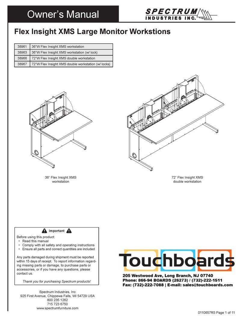
Spectrum Industries 38964 User manual

38964
38962
42" Flex Insight XMS Workstation for dual monitors (w/ lock)
42" Flex Insight XMS Workstation for dual monitors
Owner's Manual
Flex Insight XMS Dual Monitor Computer Workstation
(Single workstation for 2 monitors)
0110658R1 Page 1 of 9
Spectrum Industries, Inc.
Chippewa Falls, WI 54729, USA
IMPORTANT:
Before you begin, please make sure all parts and proper
quantities are included. Any parts damaged during
shipment must be reported within 15 days of receipt. To
report information regarding damages or if you have any
questions, please call 1-800-235-1262.
CAUTION:
Before using this product, read this manual and follow all
safety and operating instructions.
To purchase parts or accessories, please contact us at
www.spectrumfurniture.com
1-800-235-1262
Thank you for choosing Spectrum products!

(1) Unit-to-unit bracket
0107574
●Read this owners manual before assembling or operating this desk.
●Keep fingers and hands away from the edges of monitor compartment lid and clear
of the lift mechanism when raising or lowering to prevent pinching.
●Do not sit or allow students to sit on top of desk or monitor compartment lid.
●Do not exceed the maximum monitor weight rating of 32 lbs.
Safety
Hardware package contents
Asse
m
b
l
y
/
Setup
(4) 1/4-20 x15mm JC Bolts
052605
(1) 4mm Hex Wrench
025039
(1) Glide Wrench
025069
(10) 11" Zip Ties
0102376
(4) 5/16-18 x 1-5/8" Glides
025068
(4) 10-24 X 1/2" SHCS
0107683
(2) Standard Swivel VESA Monitor
Mount w/ internal travel stops
0107624
provides 4-direction tilt, and works with 75mm
and 100mm VESA monitor mounts
(includes mounting screws)
0110658R1 Pa
g
e 2 of 9
Assembly / Setup
Unlock monitor column first
Note: Every Flex Insight desk ships with one or two carriage bolts with
wing nuts locked in a keyhole slot under the bottom of the keyboard tray.
These fasteners prevent monitor column movement during shipping, and
will need to be removed to get the monitor column to function. A picture of
the bolt and wing nut is shown here from the back side of the desk. To
remove, unscrew the wing nut by hand, and slip the bolt out of the keyhole
slot. The fasteners should be retained for reuse if you will be transporting
the desk.
If you transport the desk (in a trailer or truck) it is recommended to replace
the carriage bolt and wing nut. To replace, start the wing nut on the end of
the bolt and push the monitor column down into the lowered
position. Wiggle the head of the bolt into the slot from the large side of the
keyhole. Let the monitor column rise slightly to put tension on the wing
nut. Tighten down until monitor column does not move and is secure.
Carriage Bolt
Wing Nut
Keyhole slot
Monitor column
Tools Required
Phillips and Flat Head
Screwdrivers
Glide Wrench
(included)
4mm Hex Wrench
(included)
0110658R1
Page
2
of
9

Figure 1
Installing Glides
1. Carefully lift one side of the desk and place a short wooden 4x4 or 2x4 block (or equivalent support) under the leg.
Lifting desk may require two people. Figure 1.
2. Thread the two glides into the leg, tighten securely, and remove block.
3. Repeat this procedure on the other side of the desk.
4. The glides can be adjusted with the included glide wrench to level the desk if necessary.
Glide
Leg
Wooden block
Installing CPU
1. Set the CPU unit into the CPU sling.
2. Make sure the CPU will be supported by both straps. Tighten the straps around the
CPU while keeping the buckles positioned as high as possible to avoid interference. Figure 4A.
Note:The center slot can be used for better support of
smaller profile CPU
'
s If the center slot is necessary take
0110658R1 Pa
g
e 3 of 9
Figure 4B
Figure 4A
CPU
CPU sling
straps
Strap/buckle
assembly
Center slot
CPU
CPU Sling
smaller
profile
CPU s
.
If
the
center
slot
is
necessary
,
take
the rear strap out of the rear slot and thread into the center
slot shown in Figure 4A. Thread the strap as shown in
Figure 4B.
0110658R1
Page
3
of
9

Flat Panel
Monitor
Installing Monitor
1. Attach a swivel VESA mount to each monitor with (4) 4mm PHM screws (not included-normally included with monitor). Figure 3A.
2. Loosen the back panel JC bolts on the desk slightly with a 4mm hex wrench, lift off the back panel, and open the monitor compartment lid.
3. Lift the monitor column all the way up.
4. Position and align each monitor with the monitor column mounting slots and align the VESA bracket mounting holes with the slots.
5. Attach each swivel VESA mount (with attached monitor) to the lift column with (4) 10-24 x 1/2" screws as shown in Figure 3B.
Be sure monitors do not touch.
6. Tighten screws securely.
(4) 10-24 x 1/2" SHCS
Figure 3A
(4) 4mm PHMS
(not included)
Swivel VESA
Mount
Lift Bracket
Monitor Column Slots
Note: On most flat panel monitors, it will be
necessary to remove the standard base that comes
with the monitor to use the VESA mount.
0110658R1 Page 4 of 9
Figure 3B
Monitor Column
Swivel VESA
Mount
Swivel VESA
Mount
(4) 10-24 x 1/2" SHCS
Monitor Column Slots
0110658R1
Page
4
of
9

Cord Management
1. With the back panel removed, connect the necessary monitor, keyboard, and mouse cords above the worksurface. Figure 5A.
2. Position the keyboard as shown approximately 6" from the front edge of the worksurface with the mouse on the opposite side of the
CPU as shown. This will provide enough slack in the cords during normal use and provide for left and right mouse locations.
3. With a zip tie, secure cords to the back of the storage tray as shown. The wire loom keeps monitor and keyboard cords together and
routes them while the monitors are being raised and lowered.
4. Using a flat head screwdriver, pry open each loom clip to release the wire loom. Figure 5B & 5C.
Wire loom
& clip
Monitor #1 Monitor #2
Storage Tray
0110658R1 Page 5 of 9
Figure 5B Figure 5C
Figure 5A
CPU under
worksurface
0110658R1
Page
5
of
9

Monitor #2
5. With the loom removed, feed the monitor, keyboard, and mouse cords through the sliced opening of the loom to the
bottom of the desk as shown. Figure 5D.
6. Split the CPU wires out of loom approximately 3/4 of the way down the loom and plug into CPU.
7. Reattach the loom with the clips while providing enough slack in the loom to allow the monitor column to fully extend and retract.
8. Secure the CPU cords to the bottom of the loom by attaching a zip tie around the loom directly above where the CPU cords exit the
loom. This will prevent the cords from backing out of the loom. Figure 5D.
9. Secure the CPU/Ethernet cords to the bottom of the wiring tray with a zip tie.
10. Use additional zip ties to secure other cords as needed.
Monitor #1
Wire
loom &
Lift Column
Keyboard Mouse
0110658R1 Page 6 of 9
Figure 5D
Wire loom
Loom clip
Power strip
(not included)
120VAC power
cord(s)
Use tray to secure
and store excess
cord
Wire
loom &
clip
CPU
Instructor-Side View
Zip Tie
Wiring Tray
0110658R1
Page
6
of
9

Operation
For computer use:
Connecting Desks Together
1. Desks of equal height can be connected together with the included unit-to-unit bracket. Figure 6.
2. To connect, align desks next to each other in their final location and raise monitor compartment lids.
3. Attach desks together with a unit-to-unit bracket and (4) 1/4-20 x 15mm JC bolts. Tighten bolts securely.
4. Disconnect brackets to move or relocate desks.
Unit-to-unit
bracket
Top View
Figure 6
0110658R1 Page 7 of 9
For computer use:
1. Open the monitor compartment lid. Figure 7.
2. Raise the monitors by pulling up on the lift bracket until lift column is fully extended.
3. Take the keyboard and mouse out of the storage tray and set on the worksurface.
For classroom (worksurface) use:
1. Place the keyboard and mouse in the storage tray under the monitor. Figure 8.
2. Lower the monitor by pushing down on the lift bracket until the column is fully retracted, then close the monitor compartment lid.
Note: Lockable desks can be locked at this point for security.
Lift bracket
Monitor
compartment lid
Monitor
compartment lid
Figure 7 Figure 8
Storage Tray
0110658R1
Page
7
of
9

Maintenance
After approximately 300 cycles of opening and closing, the friction dampener on the worksurface lid should be
retightened to 13 in-lbs using a torque wrench with a 4mm hex driver.
Figure 9
4mm hex
wrench
Friction
dampener
Optional Accessories
Note: If a torque wrench is unavailable, tighten the friction
damper with a 4mm hex wrench 1/8 turn at a time and
test. The correct adjustment is when the lid slows down
between 2-4" from closure. Figure 9.
0110658R1 Pa
g
e 8 of 9
Not required
20-24 lbs Order #38965 (use 2 weights)
24-27 lbs Order #38965 (use 1 weight)
Nominal weight of both monitors Counterbalance
27-32 lbs
Optional
Accessories
Monitor counter balance kit
(for lighter monitors)
kit includes two 2.5 lb weights
38965
1" Bell Glide Riser Kit
raises worksurface height from 29"
to 30" (set of 4)
98513
6-Outlet Power Strip
w/ 12' cord
115/16"W x 11/16"D x 13/16"H
99023
7-Outlet Power Strip, insured
w/surge protector, and 12' cord
10"W x 2"D x 11/8"H
99024
0110658R1
Page
8
of
9

WE WILL MAKE IT RIGHT FOR YOU!
We guarantee all Spectrum products to be free of all defects in materials and workmanship, for the original owner, for a period of ten years.
Any item deemed defective by Spectrum or the original manufacturer, under normal use conditions, will be repaired or replaced at
Spectrum’s discretion. This warranty applies to all products manufactured and distributed by Spectrum except the products listed below.
DESIGNED FOR INDOOR USE ONLY - Spectrum’s products have been designed and constructed for indoor use only. Moving or using
outdoors, or on excessively rough surfaces, may cause damage to the products and may void the warranty. If an outdoor application is
desired please contact us to discuss potential custom design solutions.
Spectrum is committed to provide complete customer satisfaction. Each of our products are manufactured from the best materials available
and each product is stringently monitored throughout the production process through our P.A.C.E. program (Product Assurance to meet
Customer Expectations).
Our Customer Service Help Line 1-800-235-1262 is ready to provide immediate attention to any questions, comments or concerns. Weare
available to answer your calls Monday through Friday from 7 am to 5 pm CST. In addition your product comments or concerns are welcome
via e-mail at: spectrum@spectrumfurniture.com.
Items that have a varying warranty include, but are not limited to, the following:
• Adjustable Crank/Electric Desk Legs (1 yr)
• Flat Panel Desk Gas Cylinders (1 yr)
• Adjustable Height Chair Parts – including frames, gas cylinders, wood and plastic parts, and control handles (7 yrs)
• Adjustable Height Chair Parts Casters (2 yrs)
• Adjustable Height Chair Upholstery - In-Stock Upholstery (2 yrs)
• Adjustable Height Chair Upholstery - Graded-In Fabrics and C.O.M (no warranty)
• Height Adjustable Columns and Lifts (1 yr)
• General Use Casters (1 yr)
• Electrical – ECA (1 yr)
• Electrical - Power Strips (1 yr)
• Electrical Surge Suppressors (lifetime)
• Electrical - Retractable Power Cords (1 yr)
• Keyboard/Mouse Trays (1 yr)
• Flat Panel Monitor Arm – General Parts (5 yrs)
Fl t P l M it A
GClid (2 )
Warranty
0110658R1 Pa
g
e 9 of 9
•
Fl
a
t
P
ane
l
M
on
it
or
A
rm
–
G
as
C
y
li
n
d
ers
(2
yrs
)
• CRT Monitor Arm (1 yr)
The warranty, as stated above, is effective as of 05/28/2009
0110658R1
Page
9
of
9
This manual suits for next models
1
Table of contents
Other Spectrum Industries Desktop manuals

Spectrum Industries
Spectrum Industries 95044 User manual

Spectrum Industries
Spectrum Industries Pivot Premier Workstation Series User manual

Spectrum Industries
Spectrum Industries Flex Insight XMS User manual

Spectrum Industries
Spectrum Industries Flex Insight XMS User manual

Spectrum Industries
Spectrum Industries Evolution TIC 38941 User manual
Popular Desktop manuals by other brands

Compaq
Compaq Presario CQ4000 - Desktop PC Quick setup

Moxa Technologies
Moxa Technologies UC-8112-ME-T-LX Hardware user manual

HP
HP Xw4400 - Workstation - 2 GB RAM Mini White Paper

HP
HP Omni 120-1300 Quick setup guide

Sharp
Sharp MZ-80A owner's manual

Rockwell Automation
Rockwell Automation 6181P user manual