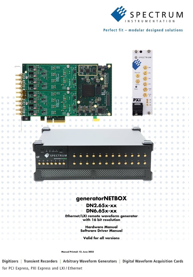
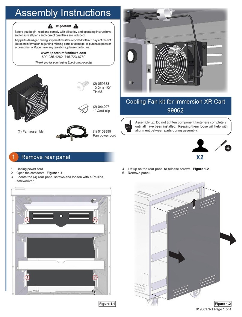
Spectrum Monaco Quad 'C6x VME64 Use and care manual

Monaco
Quad 'C6x VME64 Board
Technical Reference
Document Number 500-00191
Revision 2.00
September 1999

ii Part Number 500-00191
Revision 2.00
Copyright © 1999 Spectrum Signal Processing Inc.
All rights reserved, including those to reproduce this document or parts thereof in any form without permission in writing from
Spectrum Signal Processing Inc.
All trademarks are registered trademarks of their respective owners.
Spectrum Signal Processing reserves the right to change any of the information contained herein without notice.

Spectrum Signal Processing Monaco Technical Reference
Preface
Part Number 500-00191 iii
Revision 2.00
Preface
Spectrum Signal Processing offers a complete line of DSP hardware, software and I/O
products for the DSP Systems market based on the latest DSP microprocessors, bus
interface standards, I/O standards and software development environments. By delivering
quality products, and DSP expertise tailored to specific application requirements,
Spectrum can consistently exceed the expectations of our customers. We pride ourselves
in providing unrivaled pre- and post-sales support from our team of application
engineers. Spectrum’s excellent relationships with third party vendors provide customers
with a diverse and top quality product offering.
In 1994, Spectrum achieved ISO 9001 quality certification.
Spectrum’s Applications Engineers are available to provide technical support Monday to
Friday, 8:00 AM to 5:00 PM, Pacific Standard Time.
Telephone 1-800-663-8986 or (604) 421-5422
Fax (604) 421-1764
Email [email protected]
Internet http://www.spectrumsignal.com
To help us assist you better and faster, please have the following information ready:
• A concise description of the problem
• The names of all Spectrum hardware components
• The names and version numbers of all Spectrum software components
• The minimum amount of code that demonstrates the problem
• The versions of all software packages, including compilers and operating systems
At Spectrum, we know that accurate and easy to use manuals are important to help you
develop your applications and products. If you wish to comment on this manual, please
include the following information:
• The full name, document number, and version of the manual
• A description of any inaccuracies you may have found
• Comments about what you liked or did not like about the manual
It may be helpful for us to call you to discuss your comments. If this would be acceptable
please include your name, organization, and telephone number with your comments.
Note: Spectrum board products are static sensitive and can be damaged by electrostatic
discharges if not properly handled. Use proper electrostatic precautions whenever
handling Spectrum board products.
About
Spectrum
Contacting
Spectrum
Customer
Feedback

Monaco Technical Reference Spectrum Signal Processing
Preface
iv Part Number 500-00191
Revision 2.00
Rev. Date Changes Section
2.00 Sept 1999 Updated for TMS320C6201B and TMS320C6701
DSPs n.a.
Document
Change
History

Spectrum Signal Processing Monaco Technical Reference
Table of Contents
Part Number 500-00191 v
Revision 2.00
Table of Contents
1 Introduction..............................................................................................................................1
1.1. Features....................................................................................................................................1
1.2. Interfaces ..................................................................................................................................2
1.2.1. VME.............................................................................................................................2
1.2.2. PMC ............................................................................................................................2
1.2.3. PEM.............................................................................................................................2
1.2.4. Serial Ports..................................................................................................................2
1.2.5. JTAG...........................................................................................................................2
1.3. Reference Documents..............................................................................................................3
1.4. General Bus Architecture..........................................................................................................4
1.5. On-Board Power Supply ...........................................................................................................4
1.6. Reset Conditions.......................................................................................................................5
1.6.1. VME SYSRESET ........................................................................................................5
1.6.2. VME A24 Slave Interface Reset..................................................................................5
1.6.3. JTAG Reset.................................................................................................................5
1.7. Board Layout.............................................................................................................................6
1.8. Jumper settings.........................................................................................................................7
2 Processor Nodes.....................................................................................................................9
2.1. Processor Memory Configuration ...........................................................................................11
2.1.1. Internal Memory ........................................................................................................11
2.1.2. External Memory.......................................................................................................11
2.2. Synchronous Burst SRAM......................................................................................................15
2.3. Synchronous DRAM ...............................................................................................................15
2.4. Processor Expansion Module.................................................................................................15
2.5. Host Port.................................................................................................................................15
2.6. Interrupt Lines.........................................................................................................................15
2.7. Processor Booting...................................................................................................................16
2.8. Serial Port Routing..................................................................................................................17
3 Global Shared Bus................................................................................................................19
3.1. Memory...................................................................................................................................19
3.2. Arbitration................................................................................................................................19
3.2.1. Single Cycle Bus Access ..........................................................................................20
3.2.2. Burst Cycle Bus Access............................................................................................20

Monaco Technical Reference Spectrum Signal Processing
Table of Contents
vi Part Number 500-00191
Revision 2.00
3.2.3. Locked Cycles...........................................................................................................21
4 VME64 Bus Interface............................................................................................................23
4.1. VME Operation........................................................................................................................23
4.2. SCV64 Primary Slave A32/A24 Interface................................................................................23
4.3. A24 Secondary Slave Interface...............................................................................................24
4.4. Master A32/A24/A16 SCV64 Interface....................................................................................27
5 DSP~LINK3 Interface............................................................................................................29
5.1. DSP~LINK3 Data Transfer Operating Modes.........................................................................29
5.2. Address Strobe Control Mode.................................................................................................30
5.3. Interface Signals .....................................................................................................................31
5.4. DSP~LINK3 Reset ..................................................................................................................31
6 PCI Interface.........................................................................................................................33
6.1. Hurricane Configuration..........................................................................................................33
6.2. Hurricane Implementation.......................................................................................................36
7 JTAG Debugging...................................................................................................................37
8 Interrupt Handling..................................................................................................................39
8.1. Overview.................................................................................................................................39
8.2. DSP~LINK3 Interrupts to Node A ...........................................................................................40
8.3. PEM Interrupts........................................................................................................................41
8.4. PCI Bus Interrupts...................................................................................................................41
8.5. Hurricane Interrupt..................................................................................................................41
8.6. SCV64 Interrupt ......................................................................................................................41
8.7. Bus Error Interrupts.................................................................................................................43
8.8. Inter-processor Interrupts........................................................................................................44
8.9. VME Host Interrupts To Any Node..........................................................................................44
9 Registers...............................................................................................................................45
VPAGE Register..................................................................................................................46
VSTATUS Register .............................................................................................................47
VINTA Register ...................................................................................................................49
VINTB Register ...................................................................................................................50
VINTC Register...................................................................................................................51
VINTD Register...................................................................................................................52
KIPL Enable Register.........................................................................................................53

Spectrum Signal Processing Monaco Technical Reference
Table of Contents
Part Number 500-00191 vii
Revision 2.00
DSP~LINK3 Register ..........................................................................................................54
ID Register ..........................................................................................................................55
VME A24 Status Register....................................................................................................56
VME A24 Control Register..................................................................................................57
10 Specifications......................................................................................................................59
10.1. Board Identification ...............................................................................................................59
10.2. General .................................................................................................................................60
10.3. Performance and Data Throughput ......................................................................................61
11 Connector Pinouts...............................................................................................................63
11.1. VME Connectors...................................................................................................................64
11.2. PMC Connectors...................................................................................................................67
11.3. PEM Connectors...................................................................................................................71
11.4. JTAG Connectors .................................................................................................................73

Monaco Technical Reference Spectrum Signal Processing
Table of Contents
viii Part Number 500-00191
Revision 2.00

Spectrum Signal Processing Monaco Technical Reference
Table of Contents
Part Number 500-00191 ix
Revision 2.00
List of Figures
Figure 1 Block Diagram...................................................................................................................4
Figure 2 Board Layout.....................................................................................................................6
Figure 3 Processor Node Block Diagram......................................................................................10
Figure 4 DSP Memory Map...........................................................................................................13
Figure 5 DSP Memory Map for External-Memory Space CE1......................................................14
Figure 6 Serial Port Routing ..........................................................................................................17
Figure 7 Global Bus Arbitration .....................................................................................................20
Figure 8 Primary VME A24/A32 Memory Map ..............................................................................24
Figure 9 A24 Secondary Interface Memory Map...........................................................................25
Figure 10 PCI Memory Map ..........................................................................................................33
Figure 11 JTAG Chain...................................................................................................................37
Figure 12 Interrupt Routing............................................................................................................40
Figure 13 Connector Layout..........................................................................................................63

Monaco Technical Reference Spectrum Signal Processing
Table of Contents
xPart Number 500-00191
Revision 2.00

Spectrum Signal Processing Monaco Technical Reference
Table of Contents
Part Number 500-00191 xi
Revision 2.00
List of Tables
Table 1 Reset Summary..................................................................................................................5
Table 2 Jumper Settings..................................................................................................................7
Table 3 Processor Configurations...................................................................................................9
Table 4 'C6x Internal Peripheral Register Values..........................................................................12
Table 5 Processor Boot Source Jumpers......................................................................................16
Table 6 PEM Connections for Serial Port 0 and 1.........................................................................18
Table 7 VME and PMC Connections for Serial Port 1....................................................................18
Table 8 Global Shared Bus Access...............................................................................................19
Table 9 HPI Register Addresses...................................................................................................26
Table 10 DSP~LINK3 Data Transfer Operating Modes ................................................................30
Table 11 Hurricane Register Set...................................................................................................34
Table 12 KIPL Status Bits and the IACK Cycle.............................................................................42
Table 13 Register Address Summary............................................................................................45
Table 14 Specifications .................................................................................................................60
Table 15 Data Access/Transfer Performance...............................................................................61
Table 16 VME P1 Connector Pinout..............................................................................................64
Table 17 VME P2 Connector Pinout (PMC to VME P2)................................................................65
Table 18 VME P2 Connector (DSP~LINK3 to VME P2)................................................................66
Table 19 PMC Connector JN1 Pinout ...........................................................................................67
Table 20 PMC Connector JN2.......................................................................................................68
Table 21 PMC Connector JN4.......................................................................................................69
Table 22 Non-standard PMC Connector JN5................................................................................70
Table 23 PEM 1 Connector Pinout................................................................................................71
Table 24 PEM 2 Connector Pinout................................................................................................72
Table 25 JTAG IN Connector Pinout.............................................................................................73
Table 26 JTAG OUT Connector....................................................................................................73
Table 27 SCV64 Register Initialization..........................................................................................75

Monaco Technical Reference Spectrum Signal Processing
Table of Contents
xii Part Number 500-00191
Revision 2.00

Spectrum Signal Processing Monaco Technical Reference
Introduction
Part Number 500-00191 1
Revision 2.00
1 Introduction
This manual describes the features, architecture, and specifications of the Monaco Quad
'C6x VME64 Board. You can use this information to program the board at a driver level,
extend the standard hardware functionality, or develop custom configurations.
1.1. Features
Spectrum’s Monaco VME64 board consists of four TMS320C6x processing nodes. It is
available with either fixed-point or floating-point TMS320C6x processors.
Product Operation Processors Processor Clock Speed
Monaco Fixed-point TMS320C6201 200 MHz
Monaco67 Floating-point TMS320C6701 167 MHz
Both the Monaco and the Monaco67 are referred to as “Monaco” in this manual unless
otherwise noted.
Monaco has the following features:
• Up to four TMS320C6201 or TMS320C6701 processing nodes
• 128K x 32-bit of SBSRAM per processing node
• 4M x 32-bit of SDRAM per processing node
• Shared access to a 132 MBytes/s PMC module site via the Spectrum Hurricane chip
• 512K x 32-bit of fast, globally shared SRAM accessible to the processor nodes, PCI
interface, and VME64 interface.
• VME64 master/slave interface provided by Tundra Semiconductor’s SCV64 chip
• VME A24 slave interface access to the ‘C6x Host Port Interfaces (HPIs)
• JTAG debugging support
• Two PEM (Processor Expansion Module) sites
• DSP~LINK3 I/O interface supporting IndustryPack™ modules

Monaco Technical Reference Spectrum Signal Processing
Introduction
2Part Number 500-00191
Revision 2.00
1.2. Interfaces
In addition to the VME bus which provides the primary interface to the host computer,
the Monaco board features PMC, PEM, serial port, DSP~LINK3 and JTAG interfaces.
1.2.1. VME
Two VMEbus interfaces are provided on the Monaco board. The primary dataflow
interface supports VME64 master and slave modes for fast data transfer through the
SCV64 interface chip.
A secondary interface gives the VME A24 bus direct access to the Host Port Interface
(HPI) of each ‘C6x. This provides direct control and data transfer to and from the DSP
without interfering with dataflow on the Monaco’s Global Shared Bus.
1.2.2. PMC
The Spectrum Hurricane PCI bridge chip supports high-speed data transfer from an on-
board PMC site to the shared memory. The industry-standard IEEE-1386 PMC module
site allows developers to select from a wide variety of third-party modules.
1.2.3. PEM
Four independent high-speed, full-bandwidth, bi-directional, dataflow channels between
standard mezzanine boards (Processor Expansion Modules, or PEMs) and the ‘C6x
processors are supported. Application-specific interfaces, mounted to the PEM, are
available for computer telephony, digital radio as well as customer-specified interfaces.
1.2.4. Serial Ports
Two serial ports from each ‘C6x are available at each PEM site for on-board I/O
expansion. For each ‘C6x, one of the serial ports is always routed to the PEM site, the
second can be routed to either the PEM site or the VME P2 connector.
1.2.5. JTAG
The secondary VME interface allows access to the on-board JTAG Test Bus Controller
(TBC) from a host single-board computer for diagnostic purposes.

Spectrum Signal Processing Monaco Technical Reference
Introduction
Part Number 500-00191 3
Revision 2.00
1.3. Reference Documents
Monaco Installation Guide from Spectrum
Monaco Programming Guide from Spectrum
DSP~LINK3 Specification from Spectrum
PEM Specification from Spectrum
TMS320C6000 Peripherals Reference Guide from Texas Instruments
SCV64 User Manual from Tundra Semiconductor Corporation
Hurricane Data Sheet from Spectrum
Draft Standard Physical and Environmental Layers for PCI Mezzanine Cards: PMC
IEEE P1386.1/Draft 2.0 available from IEEE
VME64 ANSI/VITA 1-1994 available from ANSI

Monaco Technical Reference Spectrum Signal Processing
Introduction
4Part Number 500-00191
Revision 2.00
1.4. General Bus Architecture
The following block diagram shows the main components of the Monaco board.
1.5. On-Board Power Supply
There is an on-board high-efficiency DC-DC power converter that supplies +2.5V and
+3.3V power to the board from the VME 5V supply. The circuit efficiency is
approximately 90%. The +3.3V supply is available to the PEM and PMC sites, as well as
+5V and ±12V. Up to 16.5 Watts is available from the +3.3V supply for the PEM and
PMC sites. The combined +3.3V current consumption of modules on these sites must not
exceed 5 Amps.
When adding modules to the Monaco board, ensure that the power requirements for the
modules are within the specified limits, and that the system power supply and cooling are
sufficient to meet the added requirements.
SBSRAM
128K x 32
Address Buffer
and
Data Latches
Hurricane
PMC
Site
Test Bus
Controller
VME P1 Connector
SDRAM
4M x 32
DSP~LINK3 Interface
Node A
'C6x Node B
'C6x Node C
'C6x Node D
'C6x
PEM Site
PCI
Bus
VME P2 Connector
Global Shared
SRAM
512K x 32
Address Buffer
and
Data Latches
Address Buffer
and
Data Latches
Address Buffer
and
Data Latches
SBSRAM
128K x 32
SDRAM
4M x 32
SBSRAM
128K x 32
SDRAM
4M x 32
SBSRAM
128K x 32
SDRAM
4M x 32
PEM Site
Global Shared Bus
SCV64
VME64
Interface
A24 VME
Slave
Interface
JTAG
'C6x Host Port Inteface (HPI)
Figure 1 Block Diagram

Spectrum Signal Processing Monaco Technical Reference
Introduction
Part Number 500-00191 5
Revision 2.00
1.6. Reset Conditions
The Monaco board responds to three types of reset conditions:
• VME SYSRESET (VME bus /SYSRESET line)
• VME A24 Slave Interface Reset (VME A24 Control Register bit D0)
• JTAG reset (JTAG chain /TRST line)
The following table indicates which hardware components are reset by the specific reset
condition.
Table 1 Reset Summary
Reset Condition (Y = Component is Reset)
Hardware SYSRESET Slave Interface Reset JTAG Reset
Processor Nodes Y Y
SCV64 VME Interface chip Y
HPI registers Y Y
Global Shared Bus registers Y Y
VME A24 slave interface registers Y Y
JTAG (within DSPs) Y Y Y
PEM interface Y Y
PMC interface Y Y
DSP~LINK3 interface Y Y
1.6.1. VME SYSRESET
A VME SYSRESET is initiated when the /SYSRESET line on the VME bus is driven
low. All devices and registers on the Monaco board are reset to their default conditions.
1.6.2. VME A24 Slave Interface Reset
The VME A24 slave interface reset is initiated from the VME bus by setting bit D0 of
the VME A24 Control Register to “0”. All devices and registers on the Monaco board
are reset to their default conditions except for the SCV64 VME interface chip. The
VME A24 Control Register is located at VME A24 Base Address + 1004h. The base
address for the VME A24 slave interface is set by jumper block JP1.
1.6.3. JTAG Reset
The JTAG path can be reset by asserting the /TRST line of the JTAG chain by an
EMURST from the XDS or TBC. Only the JTAG path of the DSPs is reset by this
action; no other devices or registers on the board are affected.

Monaco Technical Reference Spectrum Signal Processing
Introduction
6Part Number 500-00191
Revision 2.00
1.7. Board Layout
The following diagram shows the board layout of the Monaco board.
PMC Site
PEM Site
Nodes A and B
PEM Site
Nodes C and D
J3
JN4
VME
P2
JN12 JN13
JN10 JN11
JN8 JN9
JN6 JN7
VME
P1
Node D
‘C6x
Node C
‘C6x
Node B
‘C6x
Node A
‘C6x
J1
JTAG IN
Connector
J2
JTAG OUT
Connector J8
DSP~LINK3 Ribbon Cable Connector
JN5
JN1 JN2
JP10 JP8JP9 JP7 JP4 JP5
JP3
JP2 JP1
12
34
56
78
89
10 11
12 13
Figure 2 Board Layout

Spectrum Signal Processing Monaco Technical Reference
Introduction
Part Number 500-00191 7
Revision 2.00
1.8. Jumper settings
Table 2 Jumper Settings
Jumper Description IN OUT
JP1 Pins 1-2 VME A24 slave interface base address bit A23 0 1*
JP1 Pins 3-4 VME A24 slave interface base address bit A22 0* 1
JP1 Pins 5-6 VME A24 slave interface base address bit A21 0* 1
JP1 Pins 7-8 VME A24 slave interface base address bit A20 0* 1
JP1 Pins 9-10 VME A24 slave interface base address bit A19 0* 1
JP1 Pins 11-12 VME A24 slave interface base address bit A18 0* 1
JP1 Pins 13-14 VME A24 slave interface base address bit A17 0* 1
JP2 Node A boot mode PEM HPI*
JP3 Node B boot mode PEM HPI*
JP4 Node C boot mode PEM HPI*
JP5 Node D boot mode PEM HPI*
JP7 Node A Serial Port 1 Routing VME P2 PEM*
JP8 Node B Serial Port 1 Routing VME P2 PEM*
JP9 Node C Serial Port 1 Routing VME P2 PEM*
JP10 Node D Serial Port 1 Routing VME P2 PEM*
* Default position
Note:
The default VME A24 slave interface base address is set to 80 0000h.

Monaco Technical Reference Spectrum Signal Processing
Introduction
8Part Number 500-00191
Revision 2.00
Table of contents
Other Spectrum Computer Hardware manuals