Speedball 004230 User manual
FOR ALL SPEEDBALL ETCHING PRESSES Updated August 2018
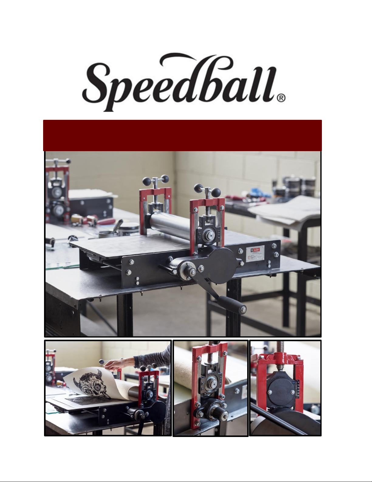
ETCHING PRESS MANUAL

2
TABLE OF CONTENTS
Delivery Notes 3
Unpacking 4
Floor Stands 6
Alignment 7
Safety Tips 7
Maintenance 8
Diagram(s)9-10
Warranty Information 11
Warranty Card 13

3
This manual is applicable to the following Speedball Etching Press models:
▪[004230] 12 x 24 Tabletop Phenolic Bed; Direct Drive; Crank Handle
▪[004231] 12 x 24 Tabletop Metal Bed; Direct Drive; Crank Handle
▪[004232] 12 x 24 Tabletop Phenolic Bed; Gear Drive; Crank Handle
▪[004233] 12 x 24 Tabletop Metal Bed; Gear Drive; Crank Handle
▪[004234] 24 x 36 Tabletop Phenolic Bed; Gear Drive; Star Wheel
▪[004235] 24 x 36 Tabletop Metal Bed; Gear Drive; Star Wheel
DELIVERY NOTES
Minimum Width of Door Opening Required:
For 12 x 24 models: 24in.
For 24 x 36 models: Phenolic Bed- 34in. | Metal Bed- 36in.
FLOOR SPACE RECOMMENDATION
For 12 x 24 models: 60in.W x 72in. L
For 24 x 36 models: 78in. W x 84in. L
WARNING: Never install the Etching Press on uneven floor.
TABLE SPACE RECOMMENDATION
All tabletop models require a sturdy wooden or metal table with larger footprint than that
of the respective Etching Press model. Table size recommendations are as follows:
For 12 x 24 models:
-Table top size (Minimum): 21in.W x 28 in. L
-Height of top surface of table from floor: 36in.
For 24 x 36 models:
-Tabletop size (Minimum): 30in. W x 38 in. L
-Height of top surface of table from Floor: 32in.
Note: Width &length of tabletop may be larger than recommendations as it is helpful to keep
essential items available when working on press.
Tabletop models must be mounted with applicable screws/bolts depending upon the
tabletop surface selection. (IE Wooden screws on wooden top surface/table or metal
screws/bolts on metal top surface/table.) Tabletop models are provided with factory-fitted
4
mounting brackets. If an Etching Press Floor Stand will be used, ensure it is on a level
surface and prepared for the Etching Press to be mounted to it appropriately.
UNPACKING
If you received your Etching Press in a corrugate box/top that was damaged during
shipment, be sure to make a full description of the breakage and/or damage as soon as
possible. Contact the delivery company immediately and make arrangements for an
inspection or return the Etching Press to their claims department.
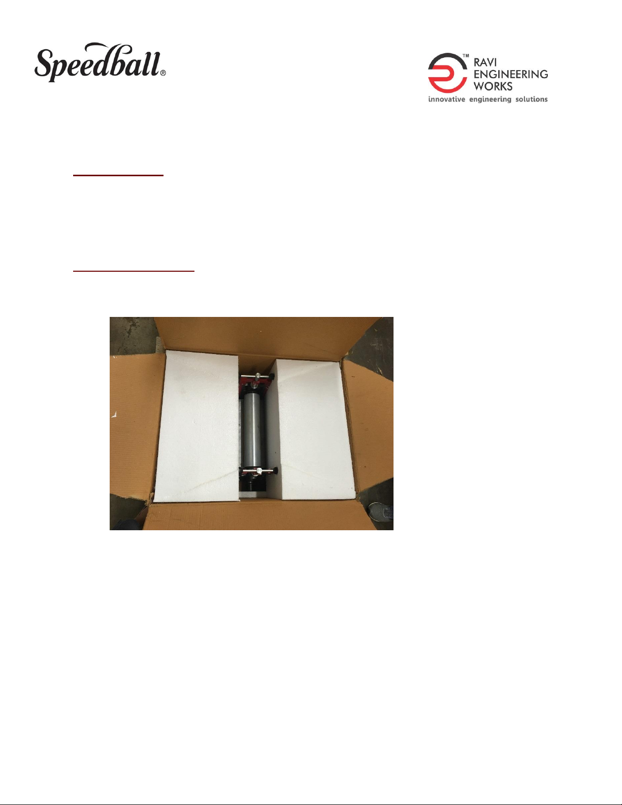
12 x 24 ETCHING PRESS
Your 12 x 24 Etching Press is packed in a heavy-duty, corrugated box. Until ready to
remove, keep the box on the floor in its upright position as marked on the box.
1. Cut the plastic straps on both the sides of the box.
2. Cut the self-adhesive tape from top of the box.
3. Identify the long side and top of the box (marked on box).
4. Cut the two vertical sides along the dotted lines of the box with a safety box cutter.
5. Flap down the cut side on the floor (the crank lever will be in front).
6. Remove the polystyrene blocks and set aside.
7. Locate and set aside the tool bag, which contains the following:
-(2) Wrenches (10-13 mm)
-(1) Black polymer handle
-(1) M8 hex bolt
5
-(1) Plain washer
-(1) M8 hex nut
-(4) Phillips head mounting screws
8. Gently slide the press from the box onto the floor.
9. With both hands, carefully lift the press from the ends and place it on your desired
tabletop. Note: Keep the crank lever off the tabletop surface.
10. Using the provided Philips head mounting screws, secure the press onto your
desired tabletop surface.
11. Using the M8 hex bolt, washer and nut, attach the black polymer handle to the end of
the crank lever.
12. Clean the press thoroughly by removing packing material, wrappings, particle
board, stretch films, dust, oil and debris.
13. For Metal Press Bed Models: Remove the yellow safety locks from the press bed.
When the press is not in use, we recommend the yellow safety locks are put in place
to prevent any type of injury.
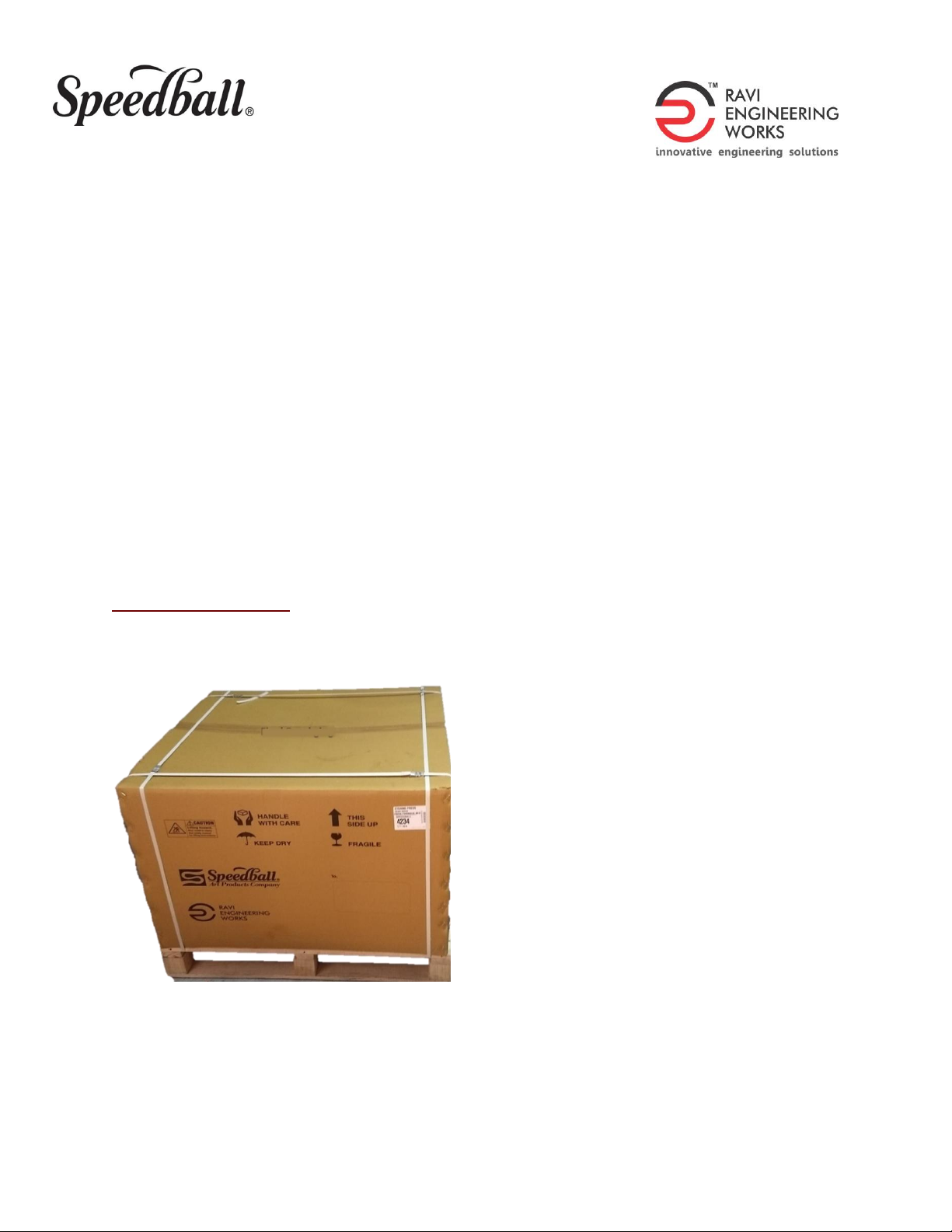
24x36 ETCHING PRESS
Your 24x36 Etching Press is packed and strapped to a 39x39 wooden pallet with a heavy-
duty corrugate TOP.
1. Remove the shrink wrap and carefully cut the plastic straps attached to the wooden
pallet.
2. Lift off the corrugated box top to remove it from the pallet.

6
3. Remove the polystyrene blocks and set aside.
4. Using Philips screwdriver, unscrew legs of press from mounting clamps (blocks of
wood) inside the frame of the press. This will “free” the press from the pallet.
-If you will be attaching your Etching Press to a Floor Stand, save one of the
blocks of wood.
5. Four persons are recommended to lift the press from the pallet to the desired
tabletop surface or floor stand*.
-*See Floor Stand Section PRIOR to lifting the press to the stand as you will need
to change the legs of the press to correctly place the press on the floor stand.
-The tabletop surface must be strong enough to withstand the weight and
pressure of the press.
6. Locate and set aside the (4) star wheel rods.
7. Locate and set aside the tool bag, which contains the following:
-(2) Wrenches (10-13 mm and 17-19 mm)
-(4) Star Wheel Rods
-(4) Knobs for Star Wheel
For your safety, the metal press bed is locked in place. DO NOT rotate the crank lever until
the following steps are completed:
8. Use the provided wrenches to reverse the position of the handle grip.
9. Remove the yellow bed locks fitted at opposite corners of the bed.
-Keep these clamps, hex bolts and nuts for future use.
10. Rotate the star-wheel slowly a quarter of a turn in both directions 3-4 times. If press
bed is travelling smoothly, turn the star-wheel by one full turn.
11. Clean the press thoroughly by removing packing material, wrappings, stretch films,
dust, oil and debris.
FLOOR STANDS
If you purchased an Etching Press Floor Stand, you need to ensure the stand is completely
level. If uneven, adjust the M10 hex bolts provided at the bottom of each leg. Tighten the
hex nut after setting up the bolt.
Floor Stand Attachment
▪Removing the press bed from your Etching Press
▪Using one of the wooden blocks from the pallet, carefully slide the block of wood
under one side of the press to lift up the press so you can get to the legs of the press.

7
▪Remove the legs currently attached to the press.
▪Replace the legs with the provided mounting clamps for the Floor Stand.
▪Once complete, repeat on the other side.
ALIGNMENT
Your Speedball Etching Press is factory-aligned, however, it can become misaligned during
shipment. Prior to use, we recommend checking the alignment to ensure it is precise.
Phenolic Bed
Check to ensure the Eccentric Pins and Reel Bearings are not interfering with the
movement of the press bed or causing the press bed to not operate smoothly.
To check alignment, rotate the crank lever or star-wheel and move the press bed all
the way through the press in both directions. If you find any issues, follow the steps
below:
▪Place one or two blankets between the upper roller and press bed.
▪Adjust the top roller by rotating top adjusters clockwise (from top viewpoint) and
lower the top roller down to create medium pressure on the blanket/press bed.
▪Eccentric Pins: Check all Eccentric Pins to ensure they touch the press bed bottom
surface.
-To adjust, using one of the provided wrenches, loosen the outer hex bolt by
one turn, rotating it counter clockwise. Once the Eccentric Pin is in its
desired position, tighten the inner hex bolt with the second provided
wrench. Repeat for each of the Eccentric Guides/Pins as necessary.
Metal Bed
Reel Bearings: Check all (4) Reel Bearings to ensure there is no interference with OR
away from the square rail on the bottom-side of bed.
-To adjust, loosen the hex bolt by one turn. Reel Bearings can be moved inward or
outward. Adjust the Reel Bearing as required and tighten the hex bolt
thoroughly. Repeat for each of the (4) Reel Bearings as necessary.
SAFETY TIPS
1. Install the Etching Press on level, durable, and strong surface.
2. DO NOT remove metal guard (safety cover) on gear-drive Etching Presses.
3. DO NOT lubricate spur gears or ball bearings; these components are lifetime
lubricated.
1. Keep hands, long hair, jewelry and loose clothing away from rollers and crank
handles when operating the Etching Press.

8
2. Keep out of the reach of small children.
3. Do not attempt to lift or move the 24x36 Etching Press by yourself. The Etching
Press should be lifted with at least three other individuals to avoid injury.
MAINTENANCE
1. For proper operation, always keep your Etching Press clean and away from water.
2. Prior to each printing session, check and if necessary, remove any dust, excess oil,
particles, ink, etc. from the press.
3. Perform the following steps periodically:
-Apply a rust preventive liquid all exposed steel surfaces primarily the Metal
bed surface and top roller surface.
-Apply an all-purpose lubricating oil on screw threads and top roller sliding
guides.
-Check all the bolts and nuts, if required, tighten them.
-Clean pressure adjusting screws accordingly.
4. If rust should appear, (don’t worry this is common and will not impact the
performance of your press) use #800 or higher Emery Paper/Cloth to remove the
rust from the press bed surface and top roller surface.
5. The pressure screws and the upright columns should be kept coated with a light
grease; this will help to prevent corrosion and ensure smooth operation.
6. When the press is not in use for an extended period of time (i.e. for more than 15
days):
-Adjust the upper roller to be tight with the bed, keeping the particle board
piece (supplied with the press) in between.
-Reverse the position of the handle grip; this will prevent the press bed from
coming out abruptly.
-Add a type of oil-based preservative on the rollers to keep them from
corroding and rusting.

9
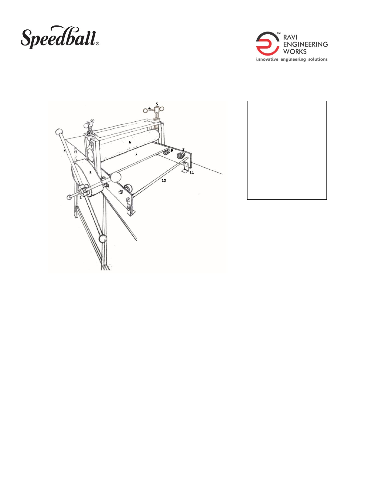
DIAGRAM
12 x 24 ETCHING PRESS | DIRECT DRIVE
12 x 24 ETCHING PRESS | GEAR DRIVE
1. Black Plastic Handle
2. Crank Lever
3. Gear Drive System
4. Pressure Lever
5. Pressure Screw
6. Top Nut
7. Top Roller
8. Bed Plate
9. Bottom Roller
10. Eccentric Guide
11. Tie Rod
12. Mounting Clamps
13. Name Plate
1. Black Plastic Handle
2. Crank Lever
3. Direct Drive System
4. Pressure Lever
5. Pressure Screw
6. Top Roller
7. Bed Plate
8. Bottom Roller
9. Eccentric Guide
10. Tie Rod
11. Mounting Clamps
12. Name Plate
10
24 X 36 ETCHING PRESS | GEAR DRIVE
1. Star Wheel Assy.
2. Star Wheel Rod
3. Gear Drive System
4. Pressure Lever
5. Pressure Screw
6. Top Roller
7. Bed Plate
8. Eccentric Guide
9. Reel Bearing
10. Tie Rod
11. Mounting Clamps

11
WARRANTY
Speedball Art Products, LLC warrants this Speedball Etching Press to be free from defects
in materials and workmanship under normal use and service, that would affect its
operation for a period of 5 (five) years from the date of purchase. This warranty applies to
the original buyer only and cannot be extended to a successive buyer even within the
warranty period.
Warranty Coverage
The obligation of this warranty shall be limited to replacing any part of the Etching Press
which, at the discretion of the Company, shall be proven defective in materials or
workmanship under normal use and service during the time period commencing with the
date of purchase. All expenses related to replacing or repairing a defective part under this
warranty shall be assumed by Speedball Art Products. The limit of this warranty includes
the product only and not any loss of work time or contract due to inability to use the
Etching Press. Full Etching Press replacement will be at the discretion of the Company and
will only be considered for claims initiated within 30 (thirty) days of purchase.
Warranty Exclusions
This warranty does not apply to any costs, repairs, or services for the following:
1. Service calls to correct the installation of the Etching Press, or to explain the usage
of the product to the buyer.
2. Repairs necessitated by use other than normal use.
3. Damage resulting from misuse, abuse, accidents, or improper installation.
4. Corrective work necessitated by repairs made by anyone other than Speedball.
5. Damage exceeding the purchase cost of the product.
6. Damage by extreme circumstances, such as flood, lighting, or natural disaster, war
declared or undeclared.
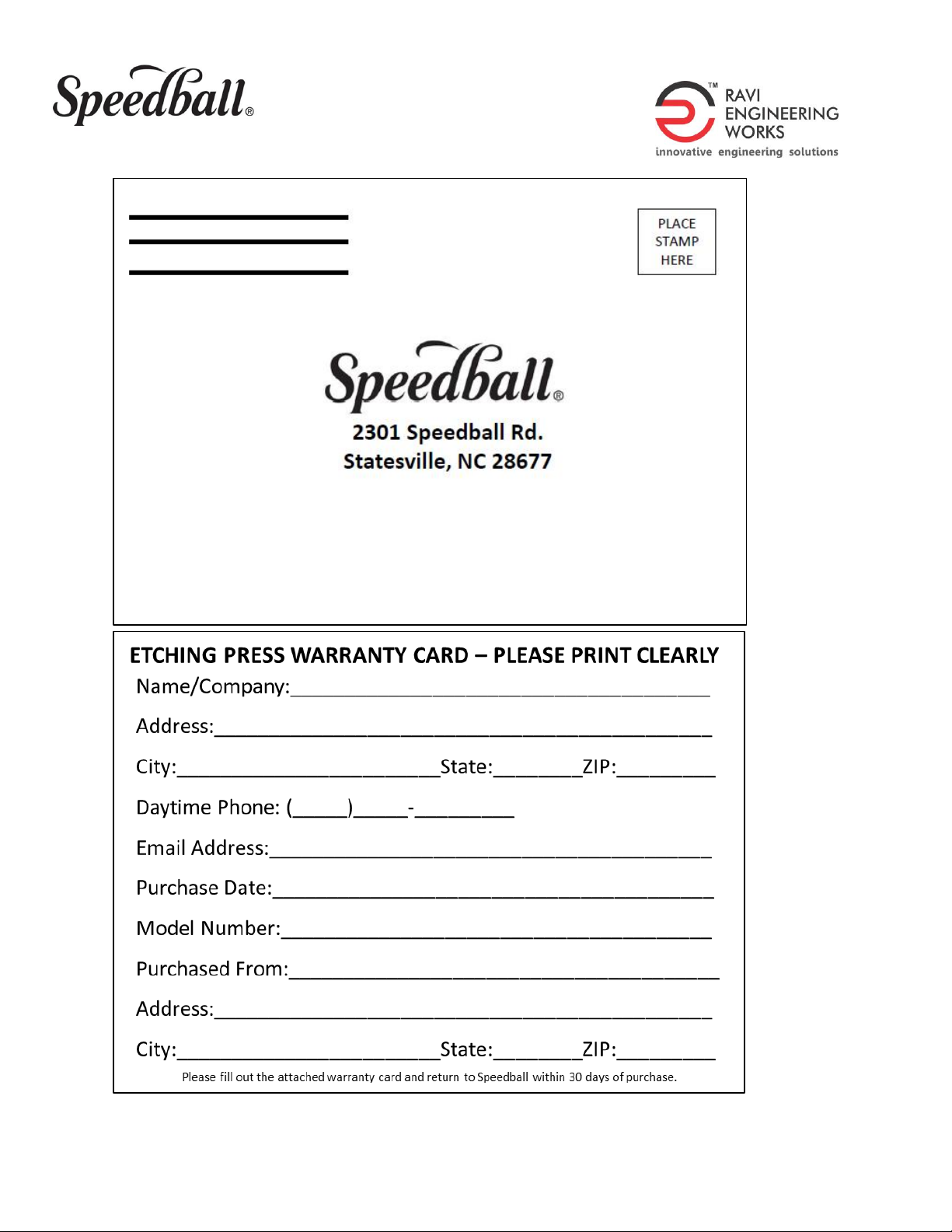
Warranty Registration
The buyer must register their Etching Press within 30 (thirty) days from date of purchase
for the warranty to be valid. There are three ways to complete the Etching Press Warranty
Card:
1. Printed Warranty Card included in original shipping box
2. Printed Warranty Card included within Etching Press Manual
3. Online –www.SpeedballArt.com under Etching Press Warranty Registration
https://www.speedballart.com/customer-service/speedball-etching-press-
warranty/

12
Warranty Replacement
If parts are in need of repair or replacement, the buyer can contact Speedball three ways:
1. Online –https://www.speedballart.com/customer-service/
2. Phone –1.800.898.7224
3. Email –pl[email protected]
13
Other manuals for 004230
1
This manual suits for next models
5
Table of contents
Popular Industrial Equipment manuals by other brands

Siemens
Siemens Sentron 3ZX1812-0WL90-0AA0 operating instructions

Abicor Binzel
Abicor Binzel CAT3 PRO Operating instruction

CDL
CDL La Fendeuse OPENING PROCEDURE AT BEGINNING OF SEASON AND CLOSING

probst
probst TSZ-UNI operating instructions

Atec
Atec PENSTOCK ECOTEC operating instructions

PVA TePla
PVA TePla IoN 3 Technical manual


Raisecom
Raisecom iTN8800 Quick installation guide

Timken
Timken ROLLON S-SMART Use and maintenance

Endress+Hauser
Endress+Hauser Liquiphant M/S FTL5 Series operating instructions

ABB
ABB HT613689 Operation manual

UnionSpecial
UnionSpecial 2000A Adjusting instructions and illustrated parts list

SeNd Technology
SeNd Technology AVIOR quick start guide