Raisecom iTN8800 User manual

1
Statement
This document is a guide to simple and convenient hardware installation. Please read it carefully before installation, to
prevent bodily injury or device damage.
The device installation personnel must be well trained before installation, to master correct installation operations and safety
precautions.
Device installation shall follow local safety regulations. Precautions listed in this document are suppliments to local safety
regulartions. Raisecom shall not be reliable to any accident if common safety operation requirements are violated, or design,
manufacturing, or usage security standards for devices are violated.
Lightning safety
Device installation is prohabited in lightning and thunderstorm conditions to prevent bodily injury and device damage.
High-voltage safety
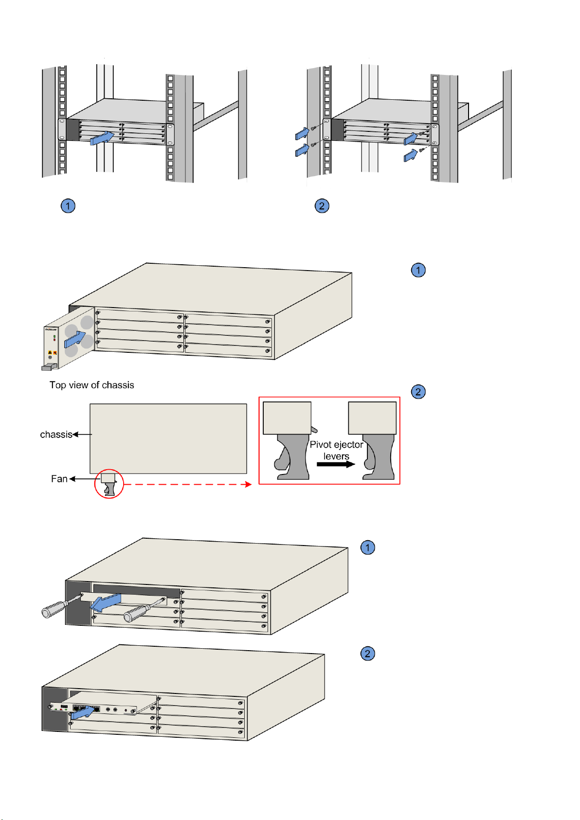
DO NOT install or remove the device when it is powered on, to prevent unpredictable bodily injury.
Use special tools instead of common tools when conducting operations in high voltage and AC power conditions.
Prevent the device from being rotted. Once the device is rotted, power off it immediately.
Electrostatic discharge safety
Any time when contacting the device, you must wear an Electro-Static Discharge (ESD) wrist strap in good contact with skin
and have the other end of the ESD wrist grounded.
Grounding safety
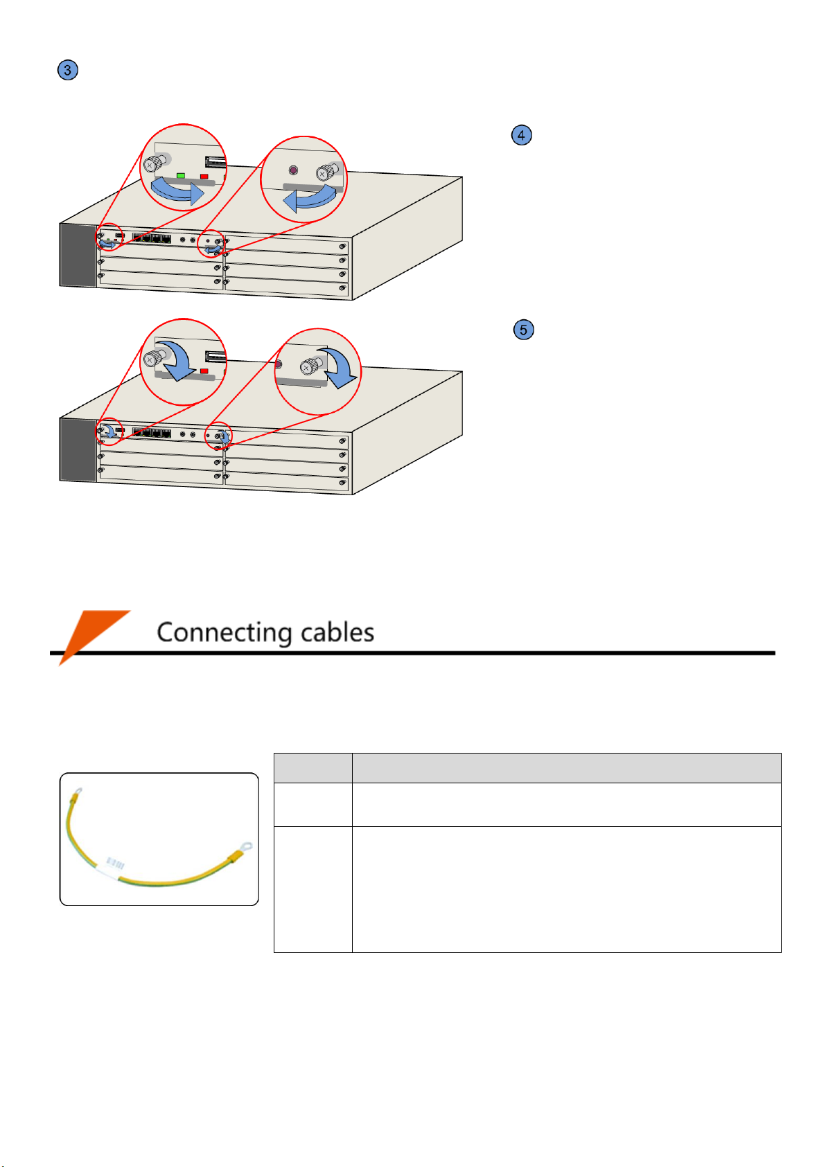
Before connecting cables, ensure that the device is fixed and is well grounded. Do not connect other cables if the device is
not grounded.
Laser safety
Before cutting or welding fiber, disconnect the fiber and the optical source. DO NOT stare into the optical interface to
prevent eye injury.

2
Item
Description
Package check
Before installing the device, check whether the device model and auxiliary parts in the package
box comply with the Packing List. If not, contact Raisecom local office or technical support.
Installing scenario
Cabinet: ETSI 600-mm cabinet, 19-inch 450-mm cabinet, or 19-inch 600-mm cabinet
Open rack
Workbench
Operating temperature
0–45°C
Operating humidity
10%–90% RH (non-condensing)
Air pressure
86–106 kPa
Anti-seismic grade
9
Power supply
conditions
The maximum overall power consumption is 300 W, so the power supply module must provide
power above this. We recommend providing a backup power supply, which can ensure that the
device runs properly when the power supply fails.
DC power supply:
Rated voltage: -48 V
Voltage range: - 40 to -57 V
ESD protection
Use effective ESD measures. The absolute value of the static voltage must be smaller than
1000 V.
Grounding condition
The device should adopt joint grounding mode, with a grounding resistance smaller than 1 Ω.
Installation tools
Diagonal pliers, cold compression pincers, flathead screwdriver, Philips screwdriver,
adjustable spanner, open-end spanner, Allen wrench, wire stripper, crimping pliers, tape
measure, level meter, crystal head crimping pliers, electric soldering iron, ESD glove, ESD
wrist, insulation tape, multimeter, optical power meter, OAMS, ground resistance tester, and
cable tester
Dimensions: 440 mm (Width) × 220 mm (Depth) × 88.1 mm (Height)

3
Installing device on cabinet
Push the chassis into the cabinet slowly.
Fix the chassis to the cabinet with screws.
Installing fan
Stably insert the fan into
the chassis along the guiderail
unless the right ejector lever
mates with the baffle on the
groove of the chassis, and then
push the fan into the groove.
Pivot ejector levers and
then push the fan inward by
holding the handles to make
the fan fully inserted into the
chassis. Release ejector levers
to make them mated with the
chassis tightly.
Installing cards
Confirm the slot into which the card is
inserted. Then, remove the blank panel.
Stably insert the card into the chassis
along the guiderail.

4
Pivot ejector levers outward at a slight 45-degree angle to make ejector levers engaged with frames of the chassis. (No
figure)
Pivot ejector levers inward to make the
card fully inserted into the chassis.
Tighten captive screws.
Installing power supply
Power cards are inserted into the left 2 slots of the chassis. There is a spring ejector lever on the front panel of the power card.
Steps for installing the power card are identical to the ones for installing the fan.
1 Connecting grounding cable
The following grounding cable is recommended.
Item
Description
Grounding
terminal
Protective grounding round pressed terminal (M4)-OT-17–15AWG
(1.2–1.5 mm2)
Grounding
cable
Name: PIL-grounding cable-Φ4-D, wherein, the letter D is the length
of the cable and can be customized. For example, if the customer
requires a 1m cable, name it PIL-grounding cable-Φ4-2m.
Yellow/Green multi-strand copper-core conducting wire 16AWG
(1.25 mm2)
Electronic wire UL1007 or UL1005 is used.

5
Connect the grounding cable.
Connect the other end of the grounding cable to the
grounding terminal of the cabinet or the grounding bar in the
equipment room.
2 Connecting Ethernet cable
Make the Ethernet cable. For details, see iTN8800 Hardware Description.
Align the header of the Ethernet cable with the Ethernet interface of the
device, and insert it properly.
3 Connecting fiber
Inserting SC/PC fiber into SFP optical interface
Insert the SFP optical module into the optical interface
on the device.
Remove the dustproof cap from the optical module and
fiber connector respectively, align the header of fiber
connector with the interface on the SFP optical module, and
insert it properly.
Inserting LC/PC fiber into XFP optical interface
Insert the XFP optical module into the optical interface
on the device.
Remove the dustproof cap from the optical module and
fiber connector respectively, align the header of fiber
connector with the interface on the XFP optical module, and
insert it properly.
4 Connecting power cable
Power adaptor and power cable
Accessory
Model
Power adapter
35A-1*2-power connector-straight female adapter/RoHS
Power cable
POL-DC-OT terminal/stripped end-18AWG-4m/RoHS

6
Do not connect the power cable without powering off the device.
Do not supply power for the device before installing the device or connecting cables.
Confirm that the grounding cable is connected properly.
Insert positive and negative poles of
the power cable into holes of the plug
and then tighten screws. (Do not
mismatch the positive and negative
poles.)
Insert the plug into the socket on the
front panel of the power card and tighten
screws to fasten the plug on the power
card. (The power card is inserted into the
chassis.)
No.
Item
Method
1
Components are installed properly without loose ends or shedding phenomenon.
View.
2
Screws are tightened.
View.
3
Cables are correctly connected without loose ends or shedding phenomenon.
View.
4
The wiring of cables should meet design requirements.
View.
5
No damage, breakage, or middle connector for signal cables
View.
6
Protective measures are taken over pigtail fiber laid outside of the cabinet, such as
equipping them with sheaths or channels.
View.
7
The radius of curvature of an optical fiber should be 20 times greater than the diameter.
In general, it should be greater than 40 mm.
View.
8
Labels on both ends of the signal cable should be correct, distinct, and neat.
View.
9
Power cables and grounding cables are connected correctly and reliably.
View.
10
The power cable and grounding cable should comply with engineering design documents
and facilitate expand capacity.
View.
11
Power cables and signal cables are laid separately.
View.
12
No fingerprints, stains, or scratches on the surface of the device
View.
13
Use a multimeter to detect the DC power supply. And ensure the voltage of the DC power
supply ranges between -40 V and -57 V.
Use a multimeter.
14
The fuse is big enough so that the device works properly under the maximum power
consumption.
View.
15
Mesure the grounding resistance of the grounding cable and grounding terminal of the
chassis. Ensure the grounding resistance is not greater than 1Ω.
Use a multimeter.

7
No.
Item
Method
1
After the device is powered on, LEDs should be in correct status. If a service interface is
connected properly with a cable, its LNK/ACT LED should be Green. If a service interface is
not connected with a cable, its LNK/ACT LED should be Off.
View.
2
The fan works properly and the LED should be in correct status. Air is circulated above the fan.
View.
3
Use the optical power meter to measure the Tx optical power (P1) of the installed SFP optical
module. Compare P1 with the metric of the SFP optical module to confirm whether the SFP
optical module works properly.
Use a
multimeter.
4
Connect the ODF-side fiber, which is connected to the device, to the optical power meter and
measure the optical power (P2). Compare P2 with P1. If difference between P2 and P1 is smaller
than 1 dB, it indicates that the fiber is connected properly.
Use a
multimeter.
Table of contents