manuals.online logo
Brands
  1. Home
  2. •
  3. Brands
  4. •
  5. Timken
  6. •
  7. Industrial Equipment
  8. •
  9. Timken ROLLON S-SMART User guide

Timken ROLLON S-SMART User guide

S-SMART
Use and maintenance - Bedienungs- und Wartungsanleitung
BELT DRIVEN
LINEAR UNITS
LINEAREINHEITEN
MIT RIEMENANTRIEB
Insert the tip of the grease gun in the specific grease blocks.
Repeat this operation every 2000 km or 1 year of use based on the
value reached first.
Type of lubricant: Lithium soap grease of class No. 2.
Amount of of lubricant necessary for re-lubrication of each slider block
For specially stressed applications or harsh environmental
conditions, lubrication should be carried out more frequently.
Apply to Rollon for further advice
Die Schmierung erfolgt an den einzelnen Schmiernippeln der Laufwagen.
Das Schmierintervall beträgt 2000 km gefahrener Weg oder eine Be-
triebsdauer von 1 Jahr. Dies ist davon abhängig, welcher Fall zuerst
eintritt.
Zu verwendendes Schmiermittel:
Lithiumseifenfett der Konsistenzklasse 2.
Bei hoher Beanspruchung oder kritischen Umgebungsbedingungen sollte
die Nachschmierung häufiger erfolgen.
Bitte halten Sie hierzu Rücksprache mit unserer Anwendungstechnik.
empfohlene Schmiermittelmenge:
Type/Typ Quantity [cm3] for greasse nipple
Menge [cm3] pro Schmiernippel
S-SMART 50 2
S-SMART 65 0,2
S-SMART 80 0,5
Lubrication - Schmierung Preliminary operations - Vorbereitende Schritte
Prior to any operation on the axis, move this one to the lower stopping point.
1 • Loosen the lock screws of the upper fastening plate
of the belt.
2 • Loosen the lock screws of the security block.
Bevor Sie die weiteren Schritte ausführen muss die Achse
sich am Endanschlag befinden.
1 • Lösen Sie die Befestigungsschrauben der Klemmplatte auf
der Seite, die dem Laufwagen gegenüber liegt.
2 • Lösen Sie die Sicherungsschraube an der Spanneinheit.
1 2
Preliminary operations - Vorbereitende Schritte
3
WARNING
Perform the same operations on both sides of the profile. For re-
assembly, perform the above operations in reverse order.
Warnung:
Führen Sie die Schritte auf beiden Seiten der Lineareinheit aus.
Zur erneuten Montage führen Sie die vorangegangenen Schritte
in umgekehrter Reihenfolge aus.
3 • Mark the traction screw of the take-up unit
and then loosen this by 6 turns.
3 • Markieren Sie die Position der Spannschraube und lösen
Sie diese dann um 6 Umdrehungen.
Replacement of the driving belt - Zahnriemenwechsel
FIRST OF ALL CARRY OUT THE OPERATIONS INDICATED AT POINTS 1-2-3
4 • Unscrew and remove the upper and lower belt fastening
plates.
FÜHREN SIE ZUNÄCHST DIE SCHRITTE 1-2-3 AUS
4 • Entfernen Sie die Befestigungsschrauben an beiden Riemenklemmungen
und entfernen Sie diese. 4
Replacement of the driving belt - Zahnriemenwechsel
5 • Release the belt from the seats on both sides of the profile
and remove it by simply pulling it out.
6 • Unscrew the 4 fixing screws of one of the endplates and then
remove the unit.
7 • Unscrew and remove the retainer placed inside the profile
8 • Remove the runner unit, being careful do not drop down the
balls from slider blocks
5
78
6
5 • Entfernen Sie den Riemen aus den Auflagen auf beiden Seiten des
Profiles. Entfernen Sie den Zahnriemen, indem Sie diesen aus dem
Antriebskopf herausziehen.
6 • Entfernen Sie die vier Befestigunsschrauben an einer der Endplatten
und entfernen Sie diese
7 • Lösen Sie die Schrauben am Anschlag innerhalb des Profiles und
entfernen Sie diesen.
8 • Nehmen Sie den Antriebskopf von der Schiene.
Achtung: Achten Sie darauf, dass die Kugeln des Führungswagens nicht
herausfallen.
Replacement of the driving belt - Zahnriemenwechsel Sliding blocks replacement - Ersetzen der Läufer
9 • Unscrew the runner-holder fixing screws and disassemble it.
10 • Insert the new belt and pass it around the driving pulley.
To re-assembly, repeat the operations above in reverse order.
9
11
10
12
BEFORE STARTING, PERFORM THE OPERATIONS FROM POINTS 1 TO 8.
11 • Remove the runner-holder blocking screws.
12 • Remove the fixing screws of slider blocks located on the carriage.
13 • Replace the blocks using the right procedure, and make sure
that they are against to reference of carriage
UM DIE EINWANDFREIE FUNKTION DER LINEAREINHEIT ZU GEWÄHRLEISTEN
MUSS DER ZAHNRIEMENWECHSEL SEHR SORGFÄLLTIG AUSGEFÜHRT WER-
DEN. ROLLON ÜBERNIMMT KEINE VERANTWORTUNG FÜR DIE FEHLERHAFTE
MONTAGE DER AUFGEFÜHRTEN TEILE.
DRIVE BELT REPLACEMENT MUST BE CARRIED OUT VERY CAREFULLY IN
ORDER TO GUARANTEE PERFECT FUNCTIONING OF THE SYSTEM. ROLLON
SHALL NOT BE HELD RESPONSIBLE FOR INCORRECT REASSEMBLY OF THE
PARTS CONCERNED.
9 • Entfernen Sie die Befestigungschrauben des Halters und entfernen
diesen.
10 • Legen sieden neuen Zehnriemen ein und führen diesen um die
Riemenscheibe herum. Zur Montage der Achse führen Sie die
vorangegangenen Schritte in umgekehrter Reihenfolge aus.
FÜHREN SIE ZUNÄCHST DIE SCHRITTE 1 BIS 8 AUS.
11 • Entfernen Sie die Befestigungsschrauben des Halters.
12 • Entfernen Sie die Befestigungsschrauben der Führungswagen.
13 • tauschen Sie die Laufwagen aus.Achten Sie dabei darauf die Referenzfläche
des neuen Wagens wieder auf der richtigen Seite zu positionieren.
Diese befindet sich gegenüber der Markierung.
Components / Komponenten
1 Head
2 Pulley unit
3 Transmission belt
4 Profile
5 Ball recirculating linear guide
6 Ball recirculatingblock
7 Belt tightener
8 Carriage
9 Runner-holder
Gearbox assembly - Montage eines Planetengetriebes
- Place the axis as shown in the figure with the gear assembly component facing upwards.
- Assemble the flange on the gear and tighten the screws until the torques shown in Table 1 are reached.
- Place the gearbox complete with flange on the unit without locking it.
- Insert the first spacer from below and then insert the keyless hub without locking it.
- Tighten the gear fixing screws.
- Gradually tighten the keyless hub fixing screws using the cross diagram until the torque shown in Table 2 is reached.
- Loosen and then tighten the gear fixing screws until the torques shown in Table 1 are reached in order for everything
to be correctly set.
Tab. 1 Tab. 2
Screw 8.8/Schrauben 8.8 Ms in Nm
M2 0.4
M2.5 0.7
M3 1.3
M4 2.8
M5 5.6
M6 9.6
M8 23
M10 46
Shrink ring screw 8.8/Spannsatzschrauben 8.8 Ms in Nm
M2.5 1.2
M3 2.1
M4 4.9
M5 10
M6 17
M8 41
M10 83
1
2
34
6
5
8
9
71 Kopf
2 Riemenscheibe mit Lagerung
3 Zahnriemen
4 Aluminiumprofil
5 Linearführungsschiene
6 Linearführungswagen
7 Laufwagen
8 Riemenspanner
9 Läufertraeger
-Platzieren Sie die Lineareinheit wie in der Abbildung rechts auf einer stabilen Unterlage.
-Montieren Sie den Adapterflansch mit den beiliegenden Befestigungsschrauben an dem Getriebe.
(Anzugsmomente siehe Tabelle1)
-Platzieren Sie das Getriebe mit montiertem Flansch auf der Lineareinheit. Beachten Sie dabei, dass die
Befestigungsschrauben nicht angezogen werden.
-Schieben Sie zuerst den Distanzring und dann den Spannsatz auf die Welle, ohne diesen zu verschrauben.
-Ziehen Sie die Befestigungsschrauben am Flansch leicht an
-Ziehen Sie die Schrauben des Spannsatzes in mehreren Schritten und über Kreuz an, bis das erforderliche Anzugsmonent (siehe Tabelle2) erreicht ist.
-Lösen Sie die Befestigungsschrauben des Flansches und ziehen Sie diese dann mit dem erforderlichen Drehmoment (Tabelle1) an.
RL_UMS-SMART_EN/D_10/18
ATTENTION WHEN INSTALLING AND MOVING.
HEAVYEQUIPMENT.
VORSICHT BEI TRANSPORT UND MONTAGE VON SCHWEREN
GEGENSTÄNDEN.
DO NOT OVERLOAD. AVOID TORSIONAL STRESS.
KOMPONENTEN NICHT ÜBERLASTEN ODER VERDREHEN.
AVOID EXPOSURE TO ATMOSPHERIC AGENTS.
VERMEIDEN SIE ES DIE LINEAREINHEIT DER WITTERUNG
AUSZUSETZEN.
IT IS ADVISABLE TO PRE-TEST THE MOTOR BEFORE
CONNECTING AND ASSEMBLING ON THE REDUCTION UNIT.
ES WIRD EMPFOHLEN, DEN MOTOR VOR DER MONTAGE AN
GETRIEBE UND LINEAREINHEIT ZU TESTEN.
AVOID DAMAGE. ALWAYS USE APPROPRIATE TOOLS.
BENUTZEN SIE IMMER GEEIGNETES WERKZEUG UM
BESCHÄDIGUNGEN ZU VERMEIDEN.
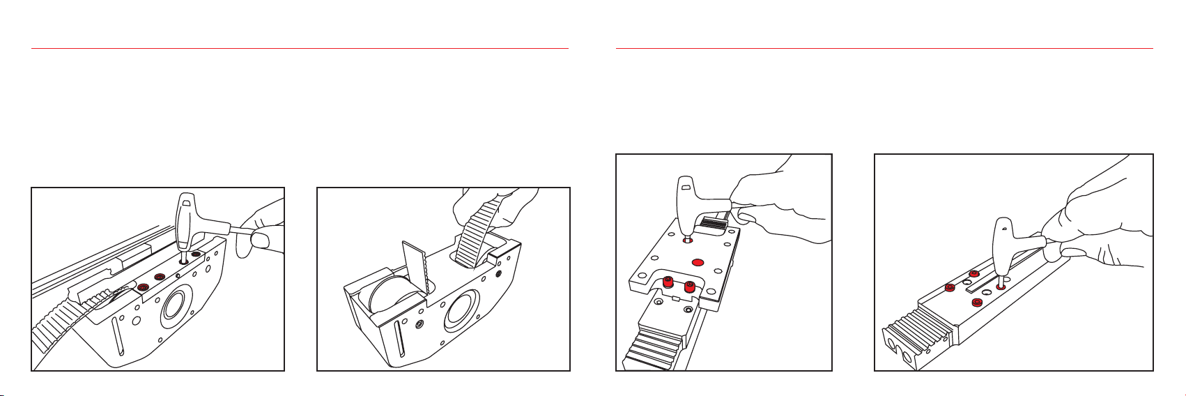
PAY ATTENTION TO MOVING PARTS. DO NOT REST
OBJECTS ON THE AXLE.
ACHTEN SIE AUF BEWEGLICHE TEILE. LASSEN SIE KEINE
TEILE AUF DER LINEAREINHEIT LIEGEN.
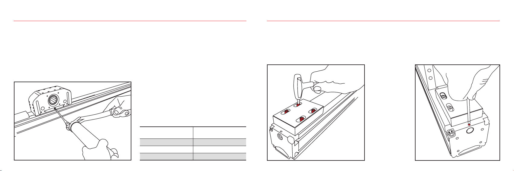
INSTALLATIONS:CHECK THE DEPTH OF THREADS ON
MOVING PARTS.
PRÜFEN SIE BEI DER MONTAGE DIE GEWINDETIEFE VON
BEWEGLICHEN TEILEN
Warnings - Anmerkungen
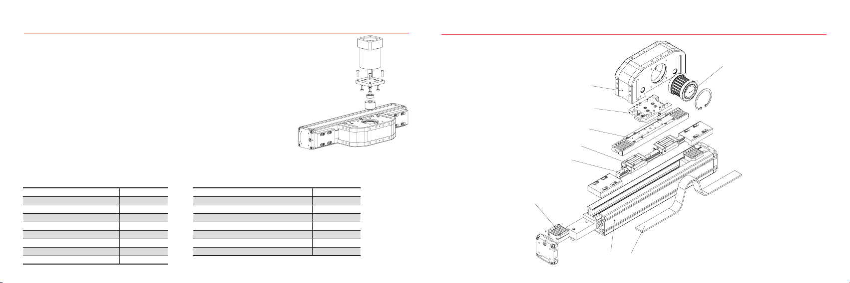
FOR FURTHER INFORMATION ABOUT TECHNICAL CHARACTERISTICS, REFER
TO OUR SPECIFIC DOCUMENTATION.
FÜR WEITERE TECHNISCHE DETAILS VERWEISEN WIR AUF UNSERE DETAIL-
LIERTERE (SPEZIFISCHE) DOKUMENTATION.
The Rollon Company shall not be held responsible for damage resulting from incorrect interpretation of these instructions.
The Rollon company reserves the right to modify its products in order to make technical improvements.
Die Rollon GmbH haftet nicht für Schäden, die durch die falsche Interpretation dieser Anleitung entstehen.
Die Rollon GmbH hat das Recht die Produkte, aufgrund von technischen Verbesserungen, zu modifizieren.
Rollon GmbH
Bonner Str. 317-319 - 40589 Düsseldorf
Phone: +49 0211957470 - Fax: +49 021195747100
E-Mail: [email protected] - www.rollon.com

Other Timken Industrial Equipment manuals

Timken ROLLON R-SMART Series User guide

Timken

Timken ROLLON R-SMART Series User guide

Timken ROLLON E-SMART Series User guide

Timken

Timken ROLLON E-SMART Series User guide

Timken Rollon ROBOT User guide

Timken

Timken Rollon ROBOT User guide

Timken ROLLON R-SMART Series User guide

Timken

Timken ROLLON R-SMART Series User guide

Timken Rollon Tecline User guide

Timken

Timken Rollon Tecline User guide

Timken ROLLON ELM Series User guide

Timken

Timken ROLLON ELM Series User guide

Timken Rollon ECO Series User guide

Timken

Timken Rollon ECO Series User guide

Timken Sheave Pac NP954426-902A1 User manual

Timken

Timken Sheave Pac NP954426-902A1 User manual

Popular Industrial Equipment manuals by other brands

Kooltronic KXHE120 Operator's manual

Kooltronic

Kooltronic KXHE120 Operator's manual

Siemens 3VA1 Series operating instructions

Siemens

Siemens 3VA1 Series operating instructions

Omron FH-5550 Setup manual

Omron

Omron FH-5550 Setup manual

MSW MSW-OD-68 user manual

MSW

MSW MSW-OD-68 user manual

BGS technic 8545 manual

BGS technic

BGS technic 8545 manual

ABB HT604903 Operation manual

ABB

ABB HT604903 Operation manual

Nilfisk-Advance PEGASUS PZC-M1 Directions for use

Nilfisk-Advance

Nilfisk-Advance PEGASUS PZC-M1 Directions for use

ABB HT573786 Operation manual

ABB

ABB HT573786 Operation manual

SUHNER MACHINING MAX40R Technical document

SUHNER MACHINING

SUHNER MACHINING MAX40R Technical document

DCD 61400-000 operating instructions

DCD

DCD 61400-000 operating instructions

Sav 890.70 operating instructions

Sav

Sav 890.70 operating instructions

SICK KTS-WB81141142ZZZZ quick start guide

SICK

SICK KTS-WB81141142ZZZZ quick start guide

Emerson CC200 quick start guide

Emerson

Emerson CC200 quick start guide

Alphacool 13093 manual

Alphacool

Alphacool 13093 manual

Rohde PW600 instruction manual

Rohde

Rohde PW600 instruction manual

Vestil STAND-G-H Series manual

Vestil

Vestil STAND-G-H Series manual

inTest Temptronic ThermoChuck TP03000 Series Operator's guide

inTest

inTest Temptronic ThermoChuck TP03000 Series Operator's guide

Emerson Roxar 6000 ps user manual

Emerson

Emerson Roxar 6000 ps user manual

manuals.online logo
manuals.online logoBrands
  • About & Mission
  • Contact us
  • Privacy Policy
  • Terms and Conditions

Copyright 2025 Manuals.Online. All Rights Reserved.