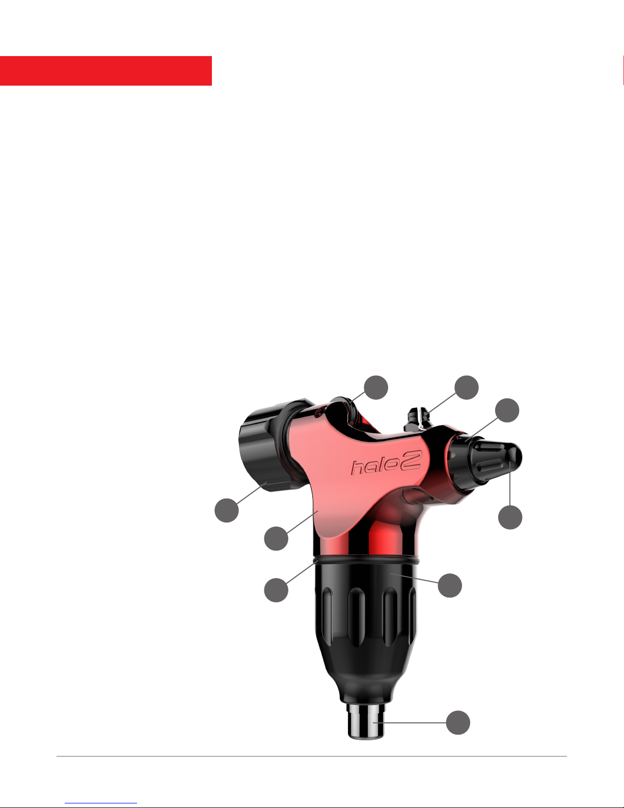
Spektra Halo 2 User manual

USER MANUAL
Crossover Machine
2018

USER MANUAL
MACHINE OVERVIEW
MACHINE FEATURES
• Compatible with standard style needles and tubes or cartridges without the need for removing
or changing parts
• Patent pending needle clip and needle stabilizer eliminate the need for grommets or rubber bands
• Interchangeable stroke wheels in 2.8mm, 3.4mm and 4.0mm sizes
• Dually compatible patent pending collet vise system supports standard back stem (5/16” - 8mm dia.)
and screw on adjustable grips
• Lightweight at only 3 ounces
• Newly designed cam system allows for increased torque and even less vibration
• Designed to push all needle groupings from single needle up to 55mags
• Adjustable give system can be modied on-the-fly to suit all styles of tattooing
• 4.5 watt Swiss Maxon Motor
• Made in the USA
MACHINE PARTS
1. MotorBolt
2. Give Adjustment Knob
3. Slider
4. Armature / Needle Clip
5. Needle Stabilizer
6. Vise Chuck
7. Machine Body
8. MotorBolt O-Ring
9. RCA Connection
PACKAGE CONTENTS
• User Manual
• Halo 2 Body
• StrokeWheel MotorBolt
• Oil Lubricant
• 0.05” Allen Key
• Spare 4-40 3/16” Stroke Set Screw
• 2.8mm Stroke Wheel
• 4.0mm Stroke Wheel
• Spare spacer washer
• Spare shaft securing O-ring
1
9
8
7
6
4
2
5
3

ARMATURE ASSEMBLY
When assembling the machine it is important to ensure that the Armature/ Needle Clip is inserted
with the extended end pointing toward the vise of the machine.
MACHINE PARTS
1. Spring
2. Spacer Washer (White)
3. Armature / Needle Clip
4. Shaft Securing O-Ring
5. Slider
6. Slider Shaft
7. Give Knob
1 3
4
2
7
5
6
1

USER MANUAL
MACHINE OVERVIEW
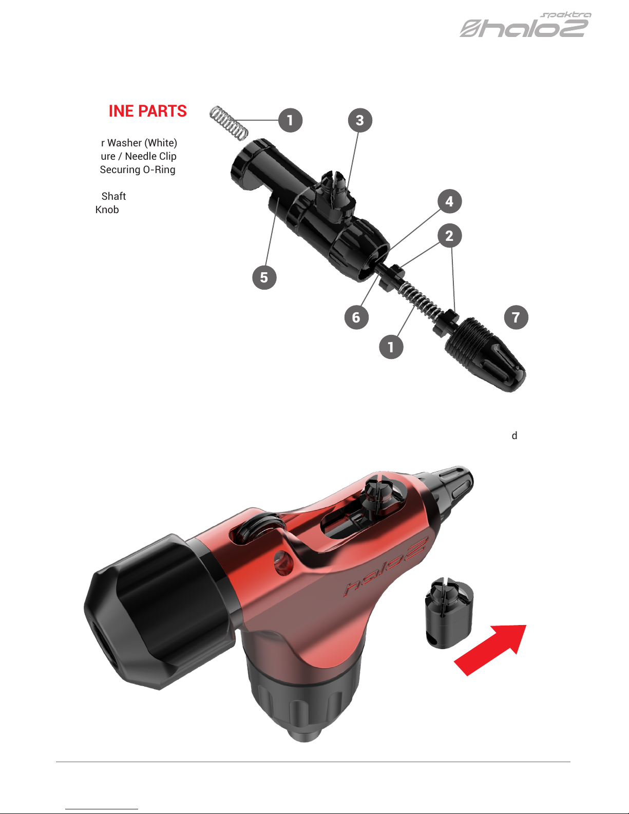
USING THE VISE & NEEDLE CLIP
The Spektra Halo 2’s patent pending collet vise system is compatible with both standard backstem style tubes
(5/16” - 8mm dia.) and Screw-on style adjustable cartridge grips
(with an M16x1mm female threading).
As assembled in the box the machine is set up to accept a standard backstem style tube.
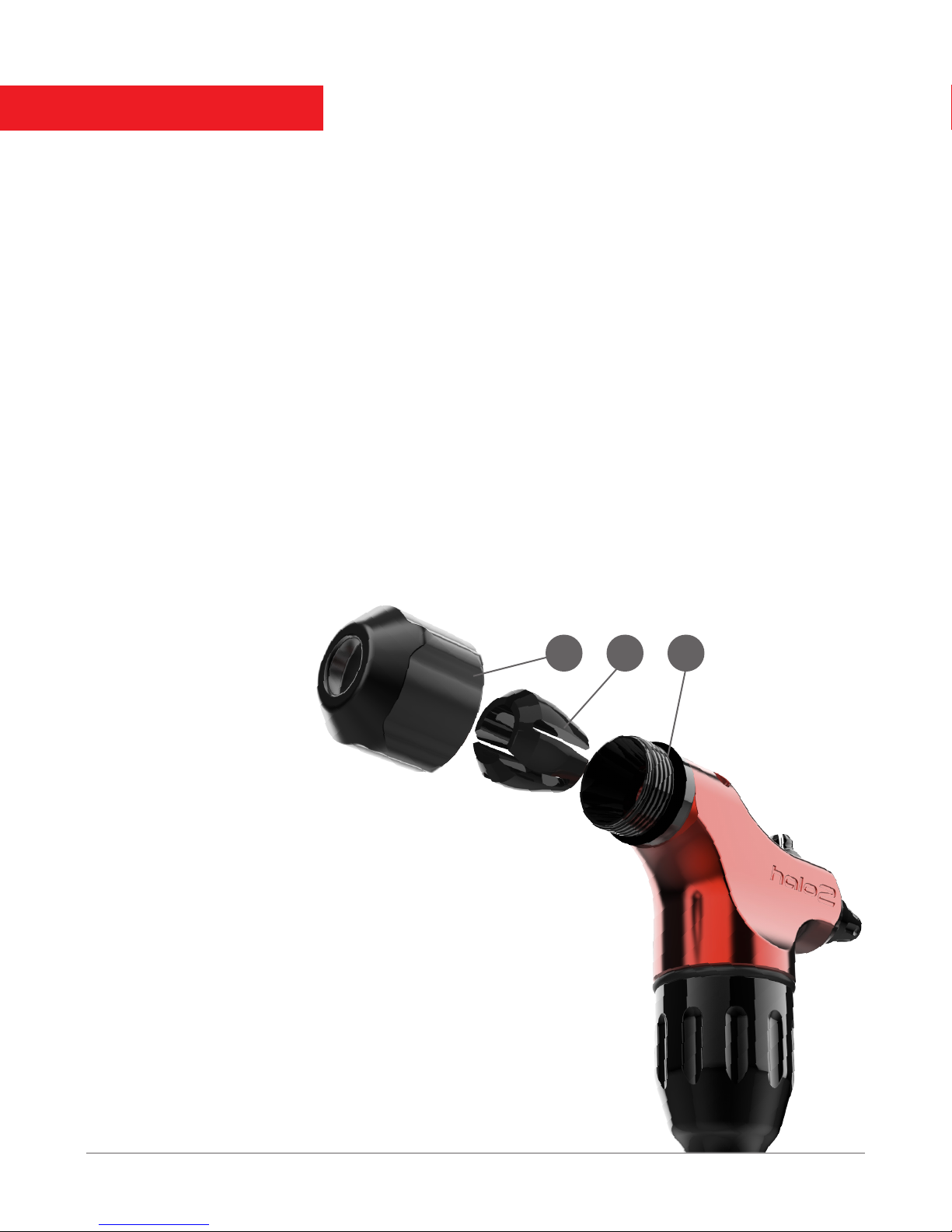
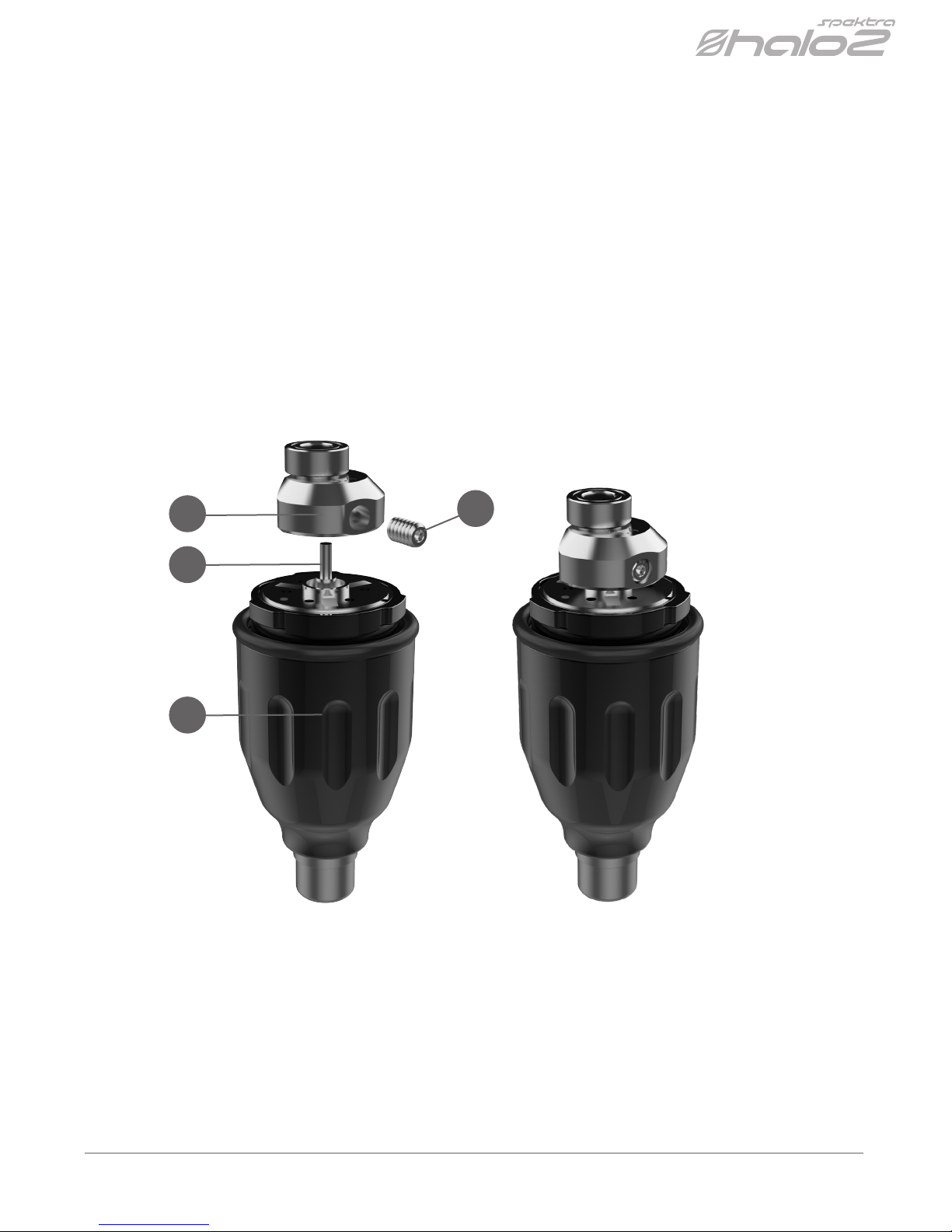
First, you will insert the needle by unscrewing the outer vise chuck (1) (enough to loosen the knob but not fully
remove it) and gently guiding the looped end of a standard needle or cartridge drive bar through the chuck, collet (2),
and vise receiver (3), then, once aligned over the Needle Clip, gently press the needle bar loop onto the Needle clip in
order to secure it in place, ensuring that the needle is centered under the Needle Stabilizer.
The Needle Clip is made to t most standard sized needle loops; if you encounter needle loops that are too large
or too small for the Needle Clip you are able to gently open or expand them with needle nosed pliers in order to
allow them to snugly t over the Needle Clip.
It is not necessary to bend the needle as the Needle Clip and Needle Stabilizer system have been designed
to accept needles straight out of their packaging, however, additional bend may be added if you desire. Be
cautious not to add too much bend as excessive tension on the needle will cause additional friction on the
slider of the machine.
123
Now, you may gently glide
the back the stem of the
tube over the drive bar or
needle and insert it into
the opening through
the vise chuck and collet,
tightening the chuck to lock in the grip.
In order to use a screw on style grip you will fully unscrew
the vise chuck (1) and remove the chuck and the exposed collet (2)
from the machine. You will need to attach the drive bar to the needle
clip then carefully insert the grip over the exposed drive bar and
attach it to the exposed threads (3).
Store the removed chuck and collet in a safe place. To transition the
machine back to accept standard backstems simply reinsert the collet
with the narrow end inserted into the vise opening and secure the chuck
onto the male threading. To remove the needle or drive bar from the
needle clip simply lift from the rear or side of the needle loop using your
ngers. Do not attempt to pull off from the needle bar shaft or use tools in
order to leverage the removal of the needle as this will cause damage to
the needle clip.

CHANGING THE STROKE
The stroke of the Halo 2 is interchangeable between 2.8mm, 3.4mm, and 4mm sizes using the included Stroke
Wheels. In order to change the stroke of the machine, release the MotorBolt unit (1) from the Machine Body and
locate the set screw opening of the mounted Stroke Wheel (3). Once you have located the set screw opening, use
the included 0.05” Hex Screwdriver to loosen the screw (4) (it is not necessary to remove the screw completely)
and release the mounted Stroke Wheel. Gently pull the full Stroke Wheel upward from the Motor Shaft (2) to
remove it. Next, use the Hex Screwdriver to loosen the set screw of the new Stroke Wheel, and gently push it
fully onto the motor shaft until it is level and touching the brass washer at the base of the exposed motor shaft.
Firmly secure the set screw in place (being carful not to over torque or strip the set screw) in order to lock the new
stroke wheel, and reinsert the motor in order to use your machine with the desired stroke length.
OPTIMAL VOLTAGE
The Spektra Halo 2 will run on any high quality rotary compatible power supply from 6.5v-14v depending on the
brand of needle / cartridge and size of the grouping that are used. Optimal voltage for the machine is generally
achieved between 7.5-10v.
Be aware that it is not suggested to run the machine above 12v to avoid over-working the skin due to the high
RPMs reached.
1
2
34

USER MANUAL
ADJUSTING THE GIVE
Your new machine comes with a fully adjustable resistance system. To fully eliminate the “give” of the machine,
turn the Give Adjustment Knob clockwise until it stops.
If you prefer to work with give, simply turn the Give Adjustment knob counter-clockwise until the desired resistance
is achieved.
The Halo 2 has an effective 5mm of give travel that has been specically designed to work with standard as well
as cartridge style needles, taking into account the internal tension of the needle cartridge. Starting with the knob
turned completely clockwise to the stopped position, turn the knob counter clockwise in full turn increments to
begin opening the give. 8 full counter clockwise turns of the knob will provide the full range of give achieved by the
machine; It is not necessary to turn the give knob beyond 8 full turns as this will result in no additional give but will
begin disassembling the machine.
It is important to note that different brands of cartridge needles contain different types of internal tensioners, so
the give response will need to be adjusted accordingly.
LUBRICATION
The slider of the Spektra Halo 2 is made of an Acetal Resin that contains PTFE and Teflon in its composition that
will reduce friction and ensure the overall smoothness and low vibration of the machine.
To prolong the life of the machine, it is recommended to apply lubricant to the slider at least once per month/ 100
hours, or when the machine begins to provide audible indication that the slider has become dry and thus causing
additional friction.
To lubricate the machine you will apply the included lubricant at at the base of the slider where it meets the Needle
Clip using 1 drop in the front of the opening and 1 drop at the rear of the opening.. You will then run the machine
at 15v for 5-6 seconds in order to disperse the lubricant, and the process is complete.
Be careful not to over-lubricate the machine as excess lubricant introduced into the tight tolerances may cause
decreased slider performance.
LIFETIME WARRANTY
FK Irons warrants that the product will perform efciently when used by a Professional Tattoo Artist. All
MachineBody components not subjected to normal wear and tear will be covered under warranty for the life of the
machine. The enclosed Maxon Motor will be covered under warranty for 1 year from the date of purchase. Should
this product be defective, FK Irons will repair or replace the product for a current available model of equal value.
This warranty will become null and void if the machine is altered or excessively mistreated in any form, including
over-lubrication of the machine components or motor. For warranty claims, replacement parts, or general service
inquiries, please read the Frequently Asked Questions section at www.fkirons.com or contact a representative via
phone at 1-855-FKIRONS. For additional tips and tutorials, please visit Youtube.com/fkirons
ADITIONAL INFORMATION
Table of contents