SPEL Smart4house RE-00 Series User manual

S4H-RE-00, S4H-RE-10 1
Wi-Fi Relay
Models S4H-RE-00, S4H-RE-10
Installation and Operating Instructions
Version for Smartphones and tablets with iOS operating system
1. Description of the Wi-Fi relay
A member of the Smart4house product family, the Wi-Fi relay is designed for remote control of
one or more devices with inputs for potential-free contacts, viz. via the Smart4house application
in your Smartphone or tablet. Requests for output relay connection/disconnection are
transmitted from the Smartphone/tablet to the cloud, from where they are transmitted to the Wi-
Fi relay through your AP –Access Point and the Wi-Fi 802.11b/g/n network. The same path is
then used by the Wi-Fi relay to send information about implementation of the request. The Wi-Fi
relay is equipped with a pair of output relays with switching contacts. The output relay status is
indicated by LED controls. The output relay either may be operated in the on/off mode or a 1-
second switch-on pulse may be generated. The information transmitted is secured by
encryption.
Two Wi-Fi relay versions differing in their power supply are marketed:
a) Model S4H-RE-00: powered with 5 VDC from a Micro B USB
a) Model S4H-RE--10: powered from a 12-24 V AC/DC supply
Note: The source for powering from USB is not included in the delivery.
2. Installation manual
Fasten Wi-Fi relay 1 to a dry, smooth and firm surface with 2 screws and wall plugs (included in
the delivery) or with a double-sided adhesive tape. To access the holes for the screws, remove
cover 2 by sliding it in the direction of the arrow. Connect the device to be controlled to the Wi-Fi
relay via screw terminals in terminal box 3.
Wi-Fi relay electronics include components which are susceptible to
electrostatic charge. Do not touch any component except the terminal box
screws and the initialising button when installing the product.

S4H-RE-00, S4H-RE-10 2
S4H-RE-00 S4H-RE-10
The Wi-Fi relay must be located within the reach of the AP/router (Access Point) signal with
which the relay will communicate and to which it will be configured. Test the AP signal quality in
the future Wi-Fi relay location on the Wi-Fi communication screen of your smartphone/tablet.
The Wi-Fi relay should be located at a well accessible site for easy initialisation, in areas with no
water vapour condensation, temperature 0°C to 50°C (32°F to 122°F). The Wi-Fi relay includes
a Wi-Fi signal transmitter/receiver and so it should not be installed at a distance of less than 20
cm from long-term presence of a human body.
2.1. Wi-Fi relay connection
S4H-RE-00 S4H-RE-10
S4H-RE-00, S4H-RE-10 3
Connect the devices to the Wi-Fi relay via terminal box 3.
RE-00 Connect the external 5 VDC power supply to the relay via Micro B USB and plug the
supply to the RE-10 network
Connect the 12 –24 V AC/DC power supply voltage to terminal box 4, terminals 9-10.
The output relays are fitted with break-make contacts: NO means that the contact is open in the
rest state. NC means that the contact is closed in the rest state.
The output relay contacts can be used as potential-free contacts or to
connect safe low PELV/SELV voltage. The contacts' maximum current
load is 1 A.
3. Commissioning the Wi-Fi relay
3. 1. Smartphone/tablet preparation
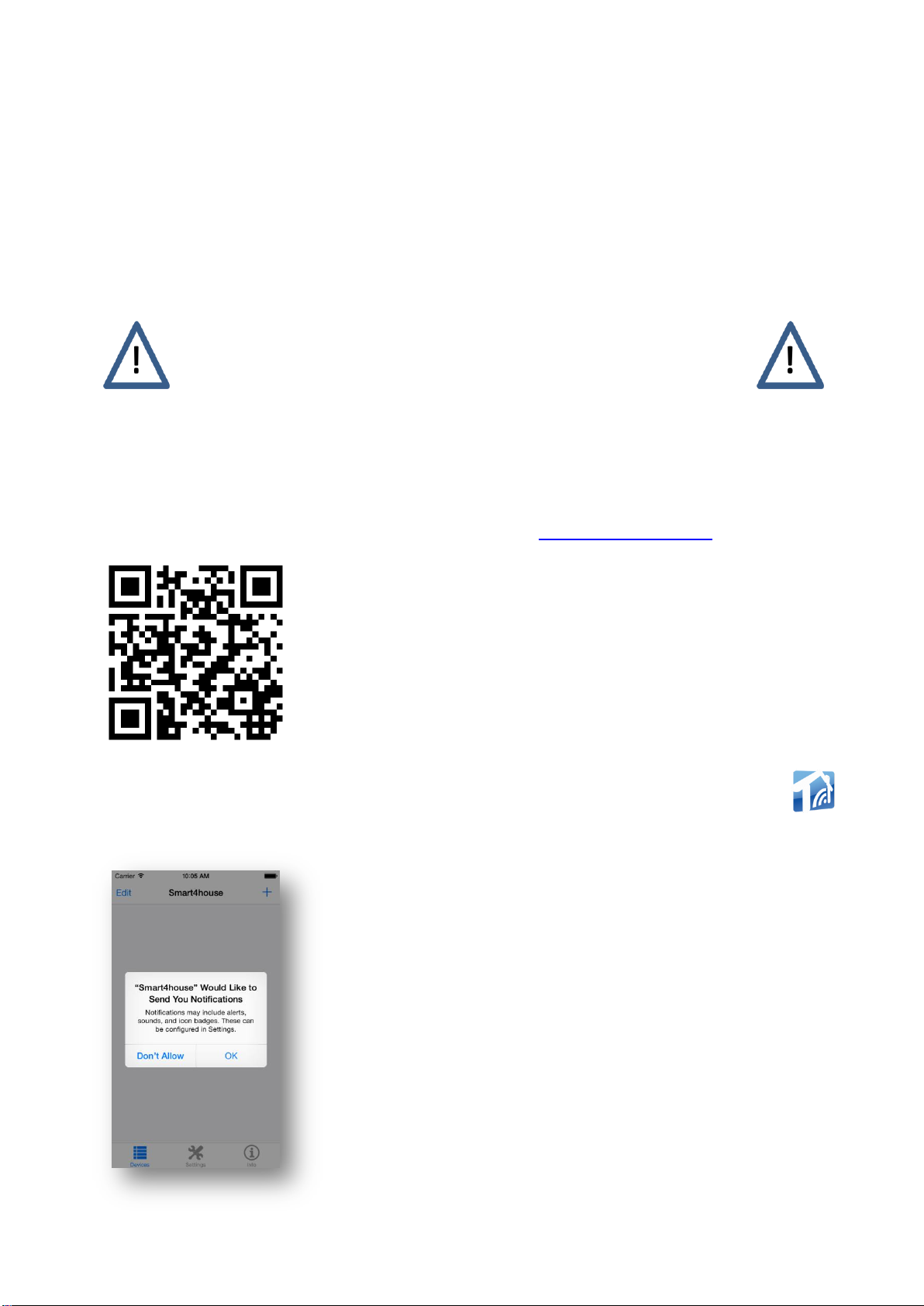
Download the free Smart4house application for iOS from App Store into your device. For this,
use either the link to the application which is available at www.smart4house.net/
or the QR code on the WiFi relay packaging.
Once the application has been successfully installed, you will find the Smart4house icon
among your icons. Click on this icon to enter the application.
When opening the application for the first time, click OK for Push
notifications to be sent to your device. The application uses APNS
(Apple Push Notification Service).

S4H-RE-00, S4H-RE-10 4
You will need the Wi-Fi relay's MAC address for setting the relay up: you will find this
information (twelve-character combination of digits and letters), identified as Device MAC, on
the label inside the removable cover 2. You will also need the name of your home network
(SSID) and the password to your Wi-Fi network.
Note: SSID - Service Set IDentifier) is a unique identifier of every wireless Wi-Fi network.
Label on the removable cover.
The MAC address is highlighted in red.
The terminal block marking is also shown
3.2. Adding the Wi-Fi relay to the Smart4house application with the iOS operating
system
Run the application and proceed in the application as follows:
3.2.a. Click the +button to add the Wi-Fi relay

S4H-RE-00, S4H-RE-10 5
3.2.b. Enter the name of your Wi-Fi relay in the Enter device
name box. It is advisable to select a name identifying the location
(e.g. boiler room, garage …), or the system controlled by the
relay (gate, pump …).
Enter the WiFi relay MAC address (see 3.1) in the Enter MAC
box and click Save.
3.2.c. Click on the box with the relay name to initialise the Wi-Fi
relay.
3.2.d. Enter the name of your AP/router network in the Network
name (SSID) box.
Enter the password of your AP/router in the Password box
When completed, click Next.
Note: Click “Edit name or MAC” if you wish to edit the data
entered sub 3.2.b.
S4H-RE-00, S4H-RE-10 6
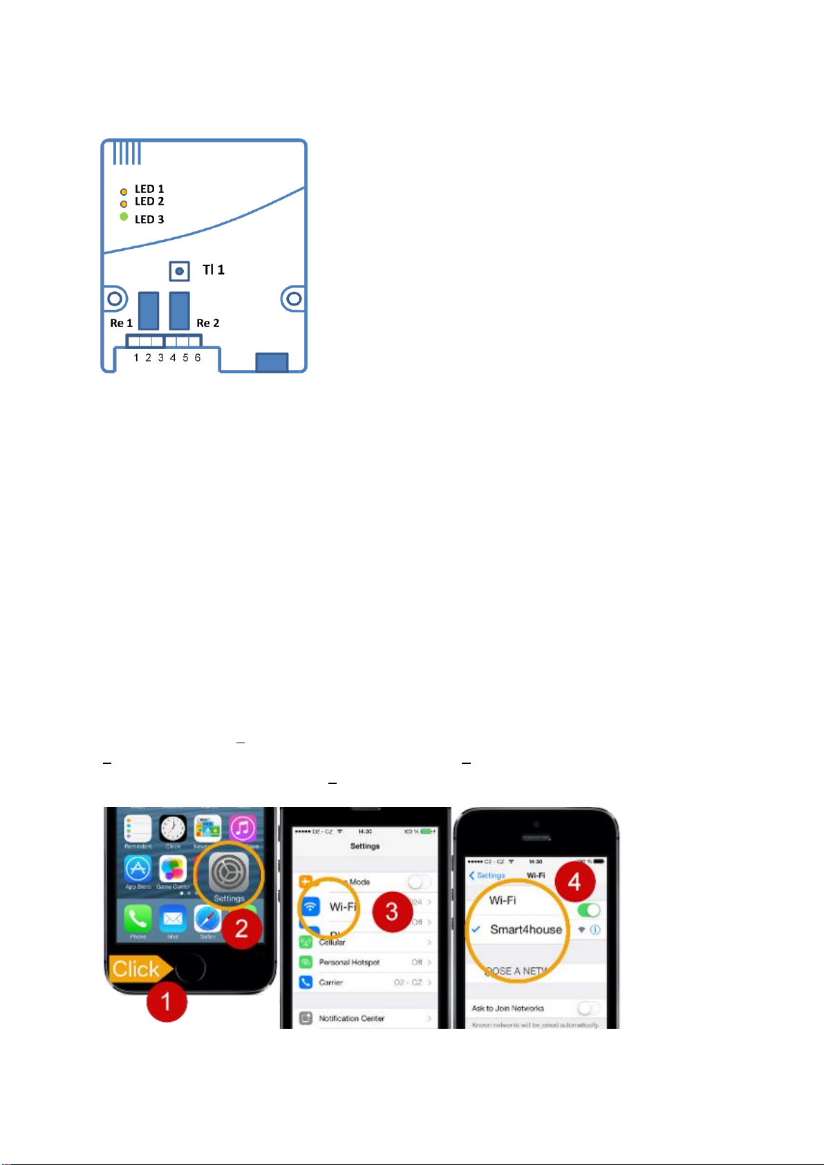
3.3. Wi-Fi relay initiation
LED 1 –orange, indicates closing of Re1 (first relay)
LED 2 –orange, indicates closing of Re2 (second relay)
LED 3 –multicolour (red, orange, green), its illumination/colour
indicate the relay initialisation steps and Wi-Fi relay connection
status during use
Tl 1 –Wi-Fi relay initialisation button
Procedure:
1. Power the Wi-Fi relay up (connect the USB connector and connect the source to the grid
or connect the 12 –24 V power supply). LED 3 will illuminate orange.
2. Press button Tl 1 in the Wi-Fi relay and hold it depressed for about 3 - 5 seconds until
LED 3 turns red. Once LED 3 illuminates red, the button may be released. The light of this LED
indicates creation of the AP mode in the relay (the Wi-Fi relay has created a provisional Wi-Fi
network named Smart4house). The AP mode duration is limited to 3 minutes, during which you
must connect your smartphone/tablet to the provisional Smart4house network.
Press Next to pass to the next screen in the application.
3. From the moment the AP mode has been created, your smartphone/tablet can be
connected to the “Smart4house” network. The procedure in the smartphone/tablet set-up will be
clear from the figure below.
Click on the button (1) of your smartphone to enter the home screen; click on the Settings icon
(2); on the Settings screen click on the Wi-Fi icon (3); and on the Wi-Fi screen click on the
temporary Smart4house network (4) to connect to the network.

S4H-RE-00, S4H-RE-10 7
Now return to the application by clicking on the icon and press Next to view the next
screen
4. Connection of the Wi-Fi relay to your smartphone/tablet is indicated by LED 3 flashing
red. The duration of this connection is limited to 3 minutes, during which you must send the
initialisation data from your smartphone/tablet to the Wi-Fi relay.
3.3.a. To send the Wi-Fi relay configuration data to your
AP/router, press the SEND TO DEVICE button on your
smartphone/tablet while LED 3 illuminates red.
Transmission of the configuration data from the
smartphone/tablet to the Wi-Fi relay is indicated by LED 3 on the
Wi-Fi relay flashing red.
Once configured, the Wi-Fi relay makes attempts to connect to
the cloud.
LED 3 illuminates orange while the Wi-Fi relay connection to your
AP is being established. Connection of the Wi-Fi relay to the
cloud is indicated by LED 3 flashing orange.
5. Once the Wi-Fi relay has connected to your home AP and then to the cloud, LED 3
starts illuminating green.
6. Test the connection between the Wi-Fi relay and your smartphone/tablet by switching
each relay on and off from the Smart4house application (after performing the steps described
below).
Note: Once the Wi-Fi relay has been successfully initialised, the provisional Smart4house
network should vanish and your smartphone/tablet should automatically switch to your AP
network. To make sure that this procedure occurred, follow these steps:
Click on the smartphone button to open the home screen; click on the Settings icon; and on the
Settings screen click on the Wi-Fi icon. The network of your AP should be active on the Wi-Fi
screen. If this has not taken place automatically, connect by clicking.
7. Close the Wi-Fi relay box with cover 2.
8. Now the device is ready for use.
Proceed as follows to check the Wi-Fi relay performance: Click on the icon to get to the
screen with a list of active devices (sensors and actuating devices). Click on a device to get to
the “Detail” screen, from which the relays can be controlled.
Activity of relay Re1 is indicated by the LED1 control illuminating, activity of relay Re2 is
indicated by the LED2 control illuminating. The COM and NO terminals are connected in the on-
state, the COM and NC terminals are connected in the off-state.

S4H-RE-00, S4H-RE-10 8
LED 3 lights during RE initialization:
3.3.b. The relays can be controlled from this screen. No
background colour button means that the relay is OFF. The
button with green background informs about the current status –
the second relay is ON.
The symbol next to the 1: button informs us that this relay
is set to the pulse mode. A 1-second pulse is generated on
pressing the button.
Press Settings (upper left) to pass to the Set device screen
3.3.c.
Button 1: controls relay Re1.
Button 2: controls relay Re2.
Control screen on tablet "in landscape mode".
Note.: In “Portrait mode” left part appear when you
swipe
from left to right.

S4H-RE-00, S4H-RE-10 9
3.3.c. The mode of the given relay can be selected here.
Normal is the ON/OFF mode.
In the Pulse mode the relay generates a 1-second pulse on
pressing the activation button on screen 3.3.b.
The active mode is indicated by blue background.
Note: The relay must be off to be switched to the pulse mode.
This screen also serves to set the Wi-Fi relay behaviour if its
communication with the cloud has been lost/resumed, or when
WiFi relay power down.
If the keep status switch is OFF ( default setting ) and connection is lost, or power goes down,
the relays will open ( safety state ). The relays will stay open after re-establishing the
communication or when power up.
If the keep status switch is ON, the WiFi relays will keep their output relays in the most recently
selected state during the communication failure period. The relays will get to the selected state
after power up.
If the Wi-Fi relay power supply fails, the two relays will be brought to the initial safe state
irrespective of the keep status switch setting. Once the power supply and, subsequently,
communication have been resumed, the output relays arrive at the preset state.
If communication between the Wi-Fi relays and the cloud is lost, the CHECK DEVICE message
is displayed on your smartphone/tablet for approximately 1 hour. The Wi-Fi relays attempt to
resume communication throughout. If you attempt to switch the output relays while no
communication exists, the system will display the message “Relay-Cloud connection is not
valid” or “Communication to relay has been lost” to inform you that the command cannot be
executed. Alternatively, the message “Relay is not responding” may be displayed to inform you
that the relay did not sent status change acknowledgment to the cloud.
If the reconnect notification switch is ON, you will always (also after a short failure) be
informed by notification that communication has been resumed.

S4H-RE-00, S4H-RE-10 10
3.3.d. Open this screen to view the control history and current
status of the outputs.
The pulse generation time is displayed if the output is in the pulse
mode.
3.3.e. Use this screen to change the device name or to pass to
the screen for Wi-Fi AP setting reconfiguration.
Note: 1: Wi-Fi relay initialisation as explained in 3.3 must be
performed if you reconfigure the Wi-Fi network.
The second relay control from this Smartphone/tablet can be
disabled by using the Second relay control symbol.
If the second relay control is disabled, the second button symbol
will not be displayed in Fig 3.3.b.
Email notifications switch is displayed only when the setting of
sending Email notifications is set to ON in Fig. 4
Press Save to save the setting.
Notes:
-If attempts to send information for Wi-Fi relay activation fail repeatedly, check the Wi-Fi
relay's MAC address, your network name (SSID) and your home Wi-Fi network password, and
repeat the procedure from the beginning.
-No limitations are imposed on the number of sensors and Wi-Fi relays displayed in one
application.
-The Wi-Fi relay status can be displayed in more than one smartphone/tablet. Fig 5
4. Sending messages by e-mail
The application allows messages on loss of communication between the Wi-Fi relay and the
cloud to be sent to your e-mail box. Proceed as follows to activate this service:

S4H-RE-00, S4H-RE-10 11
4.a. Click on the Settings icon on the bottom bar.
4. b. Click on Email notification to get to the next screen.
4.c. This screen enables you to enable/disable sending
notifications by e-mail and, if you wish, remove your e-mail
address from the cloud.
Enter your e-mail address and press Save.
Note 1.:Press Remove email if you want to remove your e-mail
address from the cloud.
Note 2.: This settings and Email address are common to all
Smart4house family devices ( sensors and actuators )
inSmart4house application.
Pressing Remove email will get you to the next screen.

S4H-RE-00, S4H-RE-10 12
4.d. To remove your e-mail address from the cloud, enter your e-
mail address and press Remove. You will receive a confirmation
message in your e-mail box. Use the link in it to remove your
address from the cloud.
This e-mail address removal procedure should be used in
situations involving reinstallation of the application or replacement
of your smartphone/tablet. The same address cannot be saved in
the new application until it has been removed from the cloud.
4.e. When you press Edit button on Fig 4.a. you will se Edit
device screen. If Email notification sre allowed, Email
notifications switch is visible.
Email notifications switch is for allow / deny sending Email
notifications to this device.
5. Wifi relay control from more than one Smartphone
5.1. When is the WiFi relay configured, you don´t need to configure WiFi setting of device in
other Smartphone/tablet. You can only add Name and MAC Fig 3.2.a. and 3.2.b. ( Name could
be different then the name in the first Smartphone )
5.2. When you change settings on the screen Set device Fig 3.3.c from any
Smartphone/tablet where is WiFi relay inserted, this settings will appear on all
Smartphone/tablet devices. The change is made immediately, on other will take effect after
reloading. The only exception is setting Reconnect notification, which can be set for each device
individually.

S4H-RE-00, S4H-RE-10 13
6. Notes
6.1. The Wi-Fi relay maintains constant connection to the cloud for its performance. This
connection uses many tools that are beyond your view control and can suffer from failures with
various durations (AP, Ethernet, servers, etc.). If the Wi-Fi relay connection to the cloud is lost,
the Wi-Fi relay will pass to its safe state: the output relays are either switched off or remain in
the last state selected (see setting 3.3.c). If, for any reason, Wi-Fi relay communication with the
cloud is lost for longer than 1 hour, a connection loss message will be sent to your
smartphone/tablet. The Wi-Fi relay will make repeated attempts to reconnect during that time. If
connection between the Wi-Fi relay and the cloud is resumed after the fault has been
eliminated, the output relays will switch to the last status selected.
6.2. The Wi-Fi relay can be controlled from several smartphones/tablets if present in their
application. The Wi-Fi relay will switch to the status sent to it (the most recent status is valid
irrespective of the device from which it was sent).
6.3. The status of the Wi-Fi relay outputs is displayed in all the smartphones/tablets that have
this relay set. However, if communication between the Wi-Fi relay and the cloud is lost, the
status existing before the loss is displayed ( automatical set to NO / OFF state after
communication lost or after power down will not appear to relay state and relay history )
6.4. When App repeatedly displays communication error and internet is working, kill the App
on background and run it again. You can do this if you press Home button twice and swipe App
Amart4house up.
7. Symbols and messages
Wi-Fi relay symbol
Relay ON symbol
Relay OFF symbol
Symbol for switching the Wi-Fi relay to the pulse mode / information on pulse
generation on the overview screen. The pulse duration is 1 second.
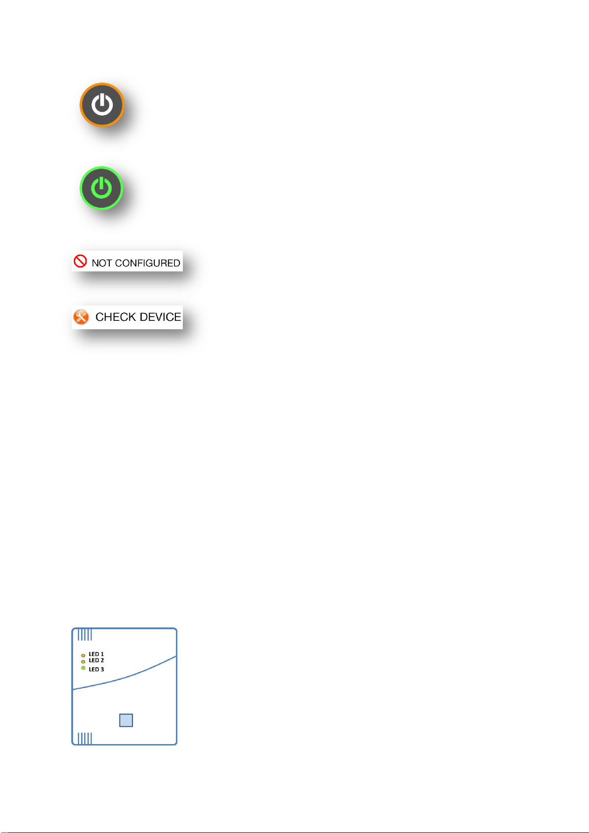
Backlit control button showing the current status of the relay in question. This
symbol shows that the relay is OFF. Pressing this button will switch the relay
on.
S4H-RE-00, S4H-RE-10 14
The orange circle around the button symbol will flash if a relay status change
request is sent. This flashing will stop once the execution of the request is
acknowledged.
A green backlit button indicates that the relay is ON. If the button is pressed
now, the reverse sequence will run.
The Wi-Fi relay is not configured to your AP/router
This message informs you that communication between the
Wi-Fi relay and the cloud has been lost for a time longer
than 1 hour. This may be due to a Wi-Fi relay failure, loss
of connection between the Wi-Fi relay and AP (increased
Wi-Fi signal attenuation, AP power supply failure) or loss of
AP connection to the Internet.
7.1. When the application is running on foreground and notification will come, every changes
are made without any other announcement. When the App is on background, notification will be
displayed on the screen.
If Emai notifications are allowed, you will get Email on selected address.
Example: Application Smart4house send you this notification:
Relay Switch RECONNECTED.
This is an automatically generated emai, please don´t reply.
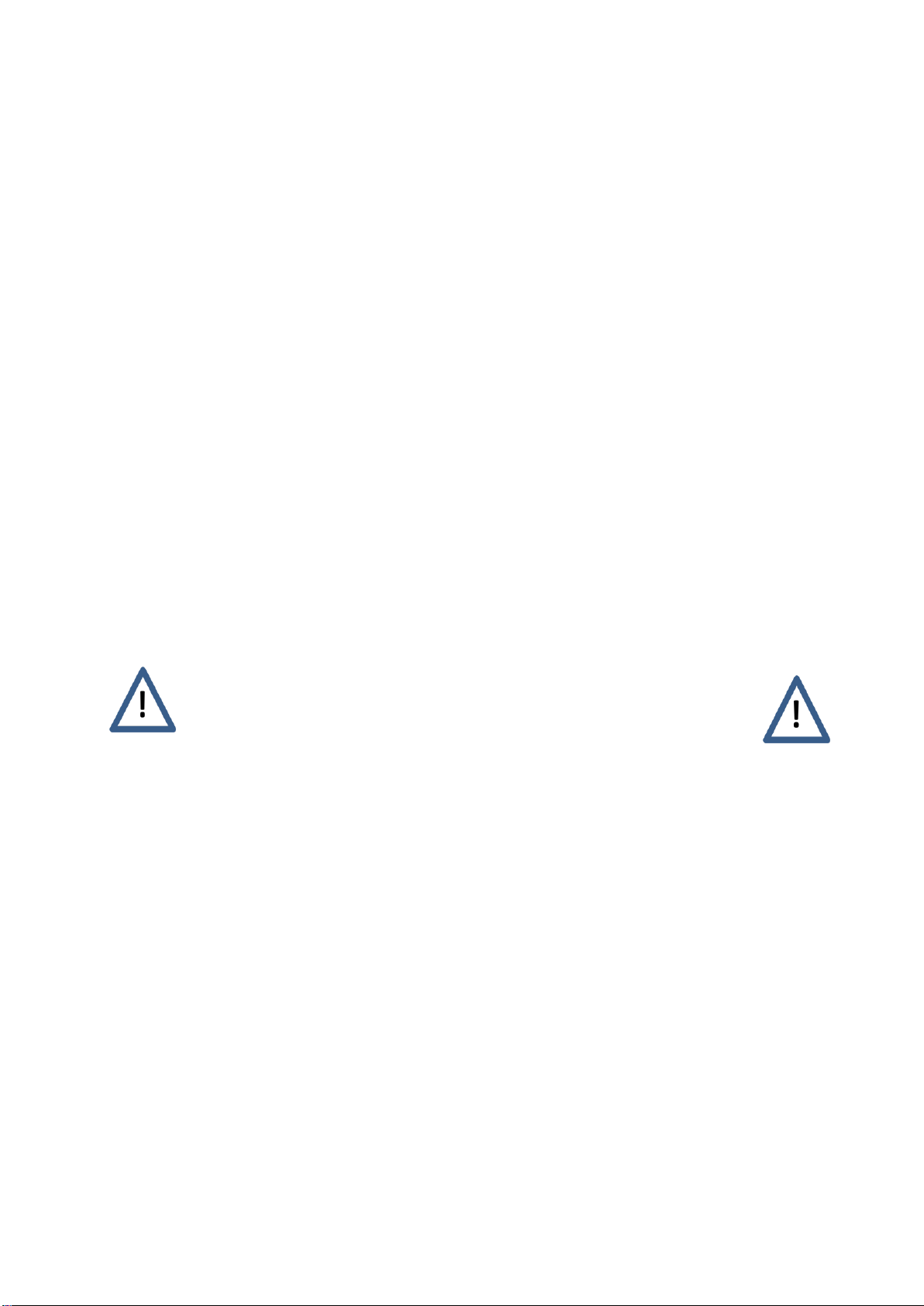
8. LED lights
Illuminating LED 1 indicates activation of Re 1 relay
Illuminating LED 2 indicates activation of Re 2 relay

S4H-RE-00, S4H-RE-10 15
8.1. Overview of Wi-Fi relay states and LED 3 lights
Colour
Light
Meaning
Mode
Orange
Illumin.
Wi-Fi relay attempts to connect to AP
Initialisation/operation
Orange
Flashing
Wi-Fi relay establishing connection to AP
Initialisation
Red
Illumin.
Wi-Fi relay formed AP S4H for 3 min
Initialisation
Red
Flashing
Data transmission from smartphone to
Wi-Fi relay
Initialisation
Green
Illumin.
Wi-Fi relay connection is OK
Operation
9. List of Wi-Fi relay messages / status change messages
The status of the Wi-Fi relay outputs can be viewed by calling the application, where the last 10
records are displayed. Each record is completed with a time stamp. Current relay status is also
indicated by the control button backlighting.
10. Error messages
The following error messages inform about faults and data transmission errors:
Another request in progress Another relay status change request is being processed,
your request cannot be executed.
Relay-Cloud connection is not valid
or Communication to relay has been lost Relay-cloud connection failure.
Cannot communicate to Cloud Connection between your smartphone and the cloud has
not been established. Examine your internet connection or
try later.
Relay is not responding Relay status change acknowledgment has not been
delivered.

S4H-RE-00, S4H-RE-10 16
11. Disclaimer
The manufacturer is not responsible for damages arising from incompetent installation or
operation. Information transmission from your smartphone/tablet to the Wi-Fi relay is associated
with the use of a number of technical tools that may affect the quality of the transmission and
are beyond the manufacturer's control. The manufacturer cannot be made liable for the
performance of such systems.
The device is not designed for security applications. Its status change information transmission
system uses the Apple Push Notification Service –APNS, which does not guarantee secure
transmission.
12. Help desk
In case of any trouble contact the manufacturer at www.smart4house.net
12.a. Technical data: Wi-Fi relay model S4H-RE-00, USB power supply
Manufactured by: SPEL a.s., Třídvorská 1402, 280 00 Kolín, Czech Republic
Size: 90 x 103 x 21 mm (3.54 x 4.06 x 0.82 in)
Weight: 90 g (3.6 oz.)
Power supply: Micro B USB –5 VDC / 500 mA
Number of outputs: 2 relays with switching contacts
Relay contact rating: 24 V AC/DC, max. 1 A, PELV/SELV
Communication: Wi-Fi 802.11 b/g/n, 2,4GHz
Receiver/transmitter: WF-121
Wi-Fi coverage: Approx. 80 m (262 ft.) - without barriers
Operating temperature: 0°C ÷ 50°C (32°F ÷ 122°F)
Intended use: For indoor use only
Certification: CE
IC –the Wi-Fi relay includes an IC Wi-Fi module ID: 5123A-
BGTWF121
FCC –the Wi-Fi relay includes an FCC Wi-Fi module ID:
QOQWF121
According to the FCC the distance between humans and the WiFi
relay should not be lower than 20 cm.
Note: The control relay contacts may be included in PELV/SELV
class circuits only.
S4H-RE-00, S4H-RE-10 17
12. b. Technical data: Wi-Fi relay model S4H-RE-10, 12 –24 V AC/DC power supply
Manufactured by: SPEL a.s., Třídvorská 1402, 280 00 Kolín, Czech Republic
Size: 90 x 103 x 21 mm (3.54 x 4.06 x 0.82 in)
Weight: 90 g (3.6 oz.)
Power supply: 12 ÷ 24 V AC/DC
Number of outputs: 2 relays with switching contacts
Relay contact rating: 24 V AC/DC, max. 1 A, PELV/SELV
Communication: Wi-Fi 802.11 b/g/n, 2,4GHz
Receiver/transmitter: WF-121
Wi-Fi coverage: Approx. 80 m (262 ft.) - without barriers
Operating temperature: 0°C ÷ 50°C (32°F ÷ 122°F)
Intended use: For indoor use only
Certification: CE
IC –the Wi-Fi relay includes an IC Wi-Fi module ID: 5123A-
BGTWF121
FCC –the Wi-Fi relay includes an FCC Wi-Fi module ID:
QOQWF121
According to the FCC the distance between humans and the WiFi
relay should not be lower than 20 cm.
Note: The control relay contacts may be included in PELV/SELV
class circuits only.
13. Equipment disposal
Dispose of the Wi-Fi relay in compliance with waste disposal laws and regulations.
RoHS: the Wi-Fi relay contains no hazardous substances. Directive 2002/95/EC.
14. Standards and certification
The Wi-Fi relay complies with the requirements of:
-EN 300 328 V1.7.1
-EN 301 489-1, V1.8.1; EN 301 489-17, V1.3.2
-EN 60950-1
-EN 61 000-4-3 ed.3:2006 +A1 +A2
-EN 61 000-4-4 ed.2:2005 +A1
-EN 61 000-4-6 ed.3:2009
-EN 55 022 ed.3: 2011 Art. 10

S4H-RE-00, S4H-RE-10 18
a) CE Declaration of Conformity.
b) ABEGU test report No. P/13/01/51.
c) The Wi-Fi relay meets FCC requirements, certificate QOQWF121.
d) The Wi-Fi relay meets IC requirements, certificate 5123A-BGTWF121.
15. Photograph of the product
Other manuals for Smart4house RE-00 Series
1
This manual suits for next models
2
Other SPEL Relay manuals


