manuals.online logo
Brands
  1. Home
  2. •
  3. Brands
  4. •
  5. Circutor
  6. •
  7. Relay
  8. •
  9. Circutor WRU-10 User manual

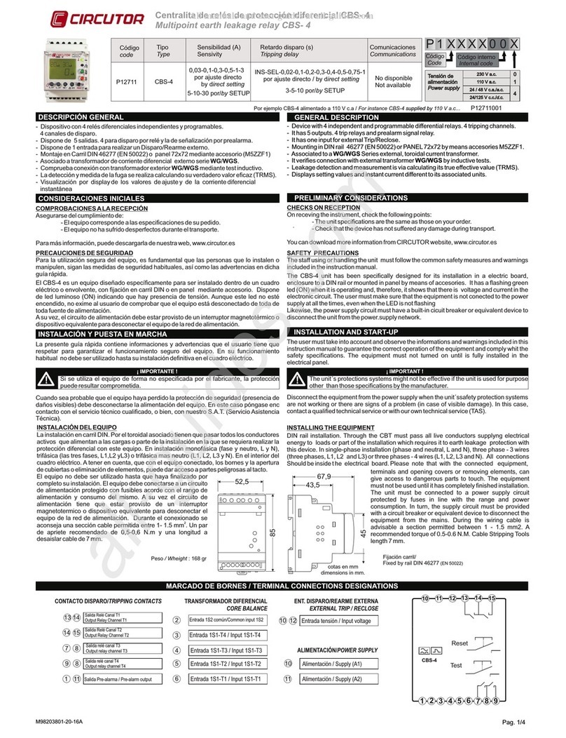
Circutor WRU-10 User manual

Code
code
Type
Type
Sensibilité (A)
Sensivity
Retard déclenchement (s)
Tripping delay
P14035001 WRU-10 0,03-0,1-0,3-0,5-1-3 par réglage direct/by direct setting
5-10-30 par/by SETUP
INS-SEL-0,02-0,1-0,2-0,3-0,4-0,5-0,75-1 par réglage direct / by direct setting
3-5-10 par/by SETUP
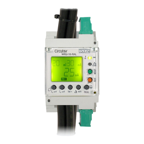
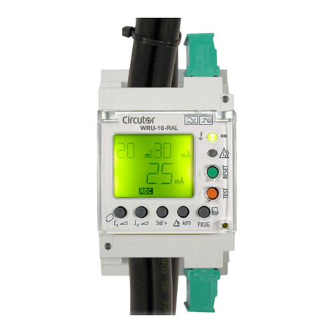
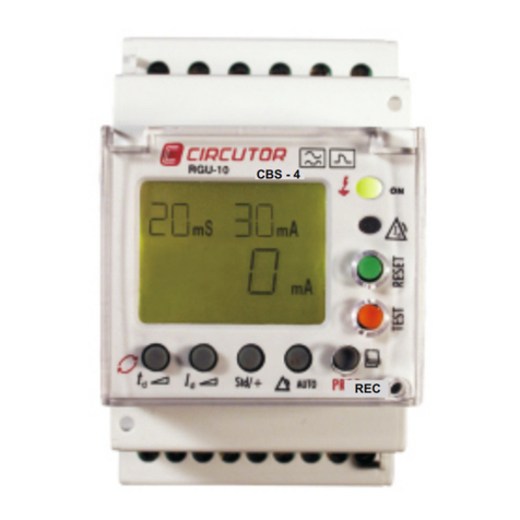
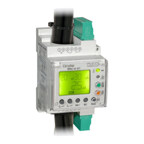
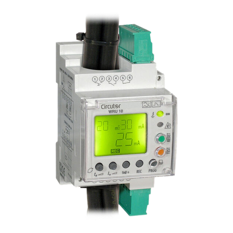
Relais de protection différentielle électronique WRU-10
WRU-10 Electronic Earth-leakage Protection Relay
R e l a i s é l e c t r o n i q u e d i f f é r e n t i e l t y p e A s u p e r - i m m u n i s é à t o r o ï d a l i n t é g r é ,
28 mm. Il dispose de relais programmables, 3 sorties. Déclenchement de relais
principal et 2 de signalisation par préalarme. Il possède une entrée libre de tension pour le déclenchement
et le réarmement extérieur. Montage sur Rail DIN 46277 (EN 50022) ou sur panneau 72x72 moyennant un accessoire (M5ZZF1). Il permet
d ' a f f i c h e r p a r d i s p l a y l e s v a l e u r s d e r é g l a g e e t d u c o u r a n t d e f u i t e i n s t a n t a n é e ( T R M S ) . .
M98237601-22-18A
CONSIDÉRATIONS INITIALES
VÉRIFICATION À LA RÉCEPTION
S'assurer de respecter que :
- L'équipement correspond aux spécifications de votre commande.
- L'équipement n'a pas subi de dommages durant le transport.
Pour une plus ample information, vous pouvez le télécharger sur notre web, www.circutor.es.
PRÉCAUTIONS DE SÉCURITÉ
Pour l'utilisation sûre de l'équipement, il est fondamental que les personnes qui l'installent ou le
manipulent, suivent les mesures de sécurité habituelles, ainsi que les avertissements de ce guide rapide.
Le WRU-10 est un équipement conçu spécifiquement pour être installé dans un tableau électrique ou une
enveloppe, avec une fixation sur rail DIN ou sur panneau au moyen d'un accessoire. Il dispose d'une diode
DEL lumineuse (ON) indiquant qu'il y a une présence de tension. Même si cette diode n'est pas allumée,
cela n'exonère pas l'utilisateur de vérifier que l'équipement est débranché de toute source d'alimentation.
INSTALLATION ET MISE EN MARCHE
¡ IMPORTANTE !
!
DESCRIPTION GÉNÉRALE
Si se utiliza el equipo de forma no especificada por el fabricante, la protección puede resultar
comprometida.
Le présent guide rapide contient des informations et des avertissements que l'utilisateur doit respecter
pour garantir le fonctionnement sûr de l'équipement. Dans son fonctionnement habituel, il ne doit pas être
utilisé avant son installation définitive sur le tableau électrique.
Lorsqu'il sera probable que l'équipement a perdu la protection de sécurité (présence de dommages
visibles) l'alimentation de l'équipement doit être débranchée. Dans ce cas, contactez le service technique
qualifié, ou bien, notre S.A.T. (Service Assistance Technique).
INSTALLATION DE L'ÉQUIPEMENT
Installation sur rail DIN. Vous devez passer à l'intérieur du trou tous les conducteurs actifs qui alimentent
les charges ou une partie de l'installation sur laquelle il faudra réaliser la protection différentielle avec cet
équipement. Dans une installation monophasée (phase et neutre, L et N), triphasée (celles à trois phases,
L1, L2 et L3) ou triphasée plus neutre (L1, L2, L3 et N). En fonction du niveau d'isolement du câblage, on
peut faire passer 4 câbles d'une section de 35 mm2, mais il est conseillé que la section soit de 25 mm2.
110 Vc.a. + 30% / -15% Température -20 ... 70 ºC Catégorie III - 300 Vc.a. EN61010
Fréquence 50/60 Hz Humidité relative 95 % Protection au choc électrique par double
Puissance 4,5 VA Hauteur max. travail 2 000 m isolement classe II, UL 1053 Certificat UL
Protection Ip20 LISTED, IEC 60755, IEC 60947-2 Annexe M
CONNEXIONS PAR BORNES ENFICHABLES
1 - 2 ENTRÉE DÉCLENCHEMENT EXTERNE
3 CONTACT SORTIE RELAIS PRÉALARME NA
4 CONTACT SORTIE RELAIS PRÉALARME COMMUN
5 CONTACT SORTIE RELAIS PRÉALARME NC
6 CONTACT SORTIE RELAIS PRÉALARME COMMUN
7 ALIMENTATION 230 Vc.a. (PHASE ou NEUTRE)
8 ALIMENTATION 230 Vc.a. (NEUTRE ou PHASE)
9 CONTACT SORTIE RELAIS DÉCLENCHEMENT NC
10 CONTACT SORTIE RELAIS DÉCLENCHEMENT NA
11 CONTACT SORTIE RELAIS DÉCLENCHEMENT COMMUN
12 SANS UTILISATION
Alimentation équipement Conditions de travail Sécurité
DESCRIPTION BORNES CARACTÉRISTIQUES
Courant nominal : 5 Ac.a.
Tension nominale : 250Vac
Charge nominale : 1 250 V·A
Courant nominal : 0,25 Ac.a.
Tension nominale : 230 Vc.a.
Charge nominale : 62,5 V·A
Libre de tension, non isolée
Protégé par varistance :
420 Vc.a. - 10 Ac.a
Super-inmunized Type A electronic relay. Built-in core balance transformer, 28 mm. It has
programmables relays, 3 outputs. Main trip and 2 pre-alarm signals. It has 1 free voltage
input for external ON / OFF. Mounting in DIN rail 46277 (En50022) or PANEL 72x72 by
means of accesories M5ZFF1. Displays setting values and instantaneous earth leakage
current value (TRMS)
GENERAL DESCRIPTION
PRELIMINARY CONSIDERATIONS
CHECKS ON RECEPTION
On receving the instrument, check the following points:
- The unit’s specifications are the same as those on your order.
- Check that the device has not suffered any damage during transport.
You can download more information from CIRCUTOR website, www.circutor.com
SAFETY PRECAUTIONS
The staff using or handling the unit must follow the common safety measures and warnings included in the
instruction manual.
The WRU-10 unit has been specifically designed for its installation in a electric board, enclosure to a DIN
rail or mounted in panel by means of accesories. It has a flashing green led (ON) when it is operation and,
therefore, it shows that there is voltage and current in the electronic circuit. The user must make sure that
the equipment is not conected to the power supply at all the times, even when the LED is not flashing.
The user must take into account and observe the informations and warnings included in this instruction
manual to guarantee the correct operation of the equipment and comply whit the safety specifications. The
equipment must not turned on until is fully installed in the electrical panel.
Disconnect the equipment from the power supply when the unit´ssafety protection systems are not working
or there are signs of a problem (in case of visible damage). In this case, contact a qualified technical service
or with our own technical service (TAS).
INSTALLING THE EQUIPMENT
DIN rail installation. On the inside of the hole must pass all live conductors supplyng electrical energy to
loads or part of the installation which requires it to earth leakage protection with this device. In single-phase
installation (phase and neutral, L and N), three phase - 3 wires (three phases, L1, L2 and L3) or three
phases - 4 wires (L1, L2, L3 and N). Depending on the level of wiring insulation can be pass through the hole
2 2
of 28 mm (inner diameter) 4-wire 35 mm of section, although it advisable is 25 mm . All connections
INSTALLATION AND STAR-UP
¡ IMPORTANT !
!
The unit´s protections systems might not be effective if the unit is used for purpose other than
those specifications by the manufacturer.
Toutes les connexions doivent se trouver à
l'intérieur du tableau électrique. Prendre en
compte que, avec l'équipement connecté, les
bornes et l'ouverture de capots ou l'élimination
d'éléments peut donner accès aux parties
dangereuses au toucher. L'équipement ne doit
pas être utilisé avant que son installation ne soit
complètement terminée. L'équipement doit être
connecté à un circuit d'alimentation protégé par
des fusibles en accord avec le rang
d'alimentation et de consommation de ce
dernier. À son tour, le circuit d'alimentation doit
ê t r e p o u r v u d ' u n i n t e r r u p t e u r
magnétothermique ou d'un dispositif équivalent
pour débrancher l'équipement du réseau
d'alimentation. Pendant la connexion, il est
recommandé d'utiliser une section de câble
permise entre 1- 1.5 mm2. Un couple de
serrage recommandé de 0,5-0,6 N.m et une
longueur de câble dénudé de 7 mm.
Should be inside the electrical board.
Please note that with the connected
equipment, terminals and opening covers
or removing elements, can give access to
dangerous parts to touch. The equipment
must not be used until it has completely
finished installation. The unit must be
connected to a power supply circuit
protected by fuses in line with the range
and power consumption. In turn, the
supply circuit must be provided with a
circuit breaker or equivalent device to
disconnect the equipment from the mains.
During the wiring cable is advisable a
section permitted between 1 - 1.5 mm2. A
recommended torque of 0.5-0.6 N.M.
Cable Stripping Tools length 7 mm.
Power supply Operating conditions Safety
Category III - 300 Vac EN61010
Double - insulated electric shock protection
clas II - UL 1053 UL LISTED Certification -
IEC 60755 - IEC 60947-2 Annex M
110 Va.c..
Frequency 50/60 Hz
Burden 4,5 VA
+ 30% / -15% Temperature -20...70 C
Relative humidity 95%
Max. Altitude 2.000 m
Protection Ip20
CONNECTIONS BY MEANS OF PLUG-IN CONNECTORS
Rated current: 5 Ac.a.
Rated voltage: 250 Vc.a.
Rated Load: 1.250 V·A
Rated current: 0,25 Ac.a.
Rated voltage: 230 Vc.a.
Rated Load: 62,5 V·A
Free voltage, not isolated
Protected by varistor:
420 Vc.a. - 10 Ac.a.
TERMINAL DESCRIPTION
1 - 2 EXTERNAL INPUT TRIP / RECLOSE
3 PRE-ALARM OUTPUT RELAY, NO
4 PRE-ALARM OUTPUT RELAY COMMON
5 PRE-ALARM OUTPUT RELAY, NC
6 PRE-ALARM OUTPUT RELAY COMMON
7 SUPPLY 230 Va.c. (Phase or Neutral)
8 SUPPLY 230 Va.c. (Neutral or Phase)
9 TRIPPING OUTPUT RELAY, NC
10 TRIPPING OUTPUT RELAY, NA
11 TRIPPING OUTPUT RELAY COMMON
12 WITHOUT USE
FEATURES
Service Assistance Technique (S.A.T.)
Dans le cas d'un doute quelconque sur le fonctionnement ou de panne de l'équipement, avertir le service
d'assistance technique.
Tél. : 902 449 459 (Espagne)
Tél. : (+34) 937 452 919 (hors d'Espagne)
Fax : (+34) 93 745 29 14
E-mail : sat@circutor.com
www.circutor.es
Vial Sant Jordi s/n
08232 Viladecavalls (Bacelone) ESPAGNE
Technical Assistance Service (T.A.S)
If you have any doubts about the running of the equipment or any faults, contact the service staff.
Tel: (+34)
Fax: (+34) 93 745 29 14
email: sat@circutor.com
www.circutor.es
937 452 919
Vial Sant Jordi s/n
08232 Viladecavalls (Bacelona) SPAIN
Note: Circutor guarantees that the WRU-10 device complies with a response time of less
than 30 ms to 5In, and in combination with the selected cutting element must guarantee a
total cut-off time of less than 40 ms to comply with the IEC 60947-2-M standard.
RGU - 10 C
Avec le bouton-poussoir nous naviguons dans les
sous-menus et avec le bouton-poussoir nous
visualisons les valeurs à choisir. Nous validons la valeur en
appuyant sur , nous visualisons « SAVE » et nous
quittons le SETUP. Avec le clavier inactif, l'équipement sort
automatiquement du mode de programmation et affiche «
EXIT » sans changer la configuration.
PROG
PROG
Pulsador
Pulsador PROG
FREC
LIM
Pulsador
50 Hz
60 Hz
10 s, 30 A
1 s, 3 A
PROG
+
REC
PROG
SCHÉMAS DE CONNEXION / WIRING DIAGRAM
Relais de protection différentielle électronique WRU-10
WRU-10 Electronic Earth-leakage Protection Relay
M98237601-22-18A
- .
.
- .
.
- BY TRIP.
l.
- BY PREALARM.
.
( t, I and std/+ )
d d
- , t.
d
td
.
SAVE.
- , I. I.
dd
- , std/+.
.
( t, I,std/+ and Auto)
d d
.
- , t.
d
- , I. S
d
(OFF-50-60-70-80-MAIN).
- , std/+. S .
- , Auto. A
.
SETUP
A
.
INDICATION BY LED AND DISPLAY
MAIN TRIP RELAY LED and display signals a change of status by changing from green to red.

Display event type messages or values
PREALARM SIGNAL. The yellow LED only comes on when current leakage exceeds the preset
prealarm threshold
RECLOSING THE EQUIPMENT
A manual RESET, or remote ON is required to return to the equipment's initial status.
When the trip is caused by the remote OFF signal, it can only be re-armed by the remote ON
signa
A manual RESET has to be performed if it is in non-automatic mode to cancel
this status
MAIN RELAY PARAMETER SETTING
SETTING TRIP DELAY The message and two values appear on the screen after
pressing the button. The lowest value indicates the current set value and the highest is the
values to be configured which are displayed by pressing The selected value to be saved is
displayed by showing the message
SENSITIVITY SETTING The same operation as above setting is carried out by pressing
SAFETY SETTING The required safety type through changing the trip contact polarity
is selected by pressing this button. (Std) Standard nothing appears on the display and (+)
Positive, the symbol appears
PREALARM RELAY SETTING PARAMETERS
A short press on PROG enters the prealarm channel activating the Alarm message on the display
DELAY SETTING . Select the time delay for giving the prealarm signal
SENSITIVITY SETTING elect the equipment's prealarm threshold. Selected sensitivity
stated as % in the main channel
POLARITY SETTING elect the prealarm output signal polarity
SETTING OF RESET OF PREALARM ctivating , the equipment automatically
resets the prealarm when the leakage current drops below the preset alarm threshold
SETTINGS
long press on PROG activates the setting menu . Using the PROG and buttons in
this operating mode moves and changes the preset equipment values in the different setting
submenus
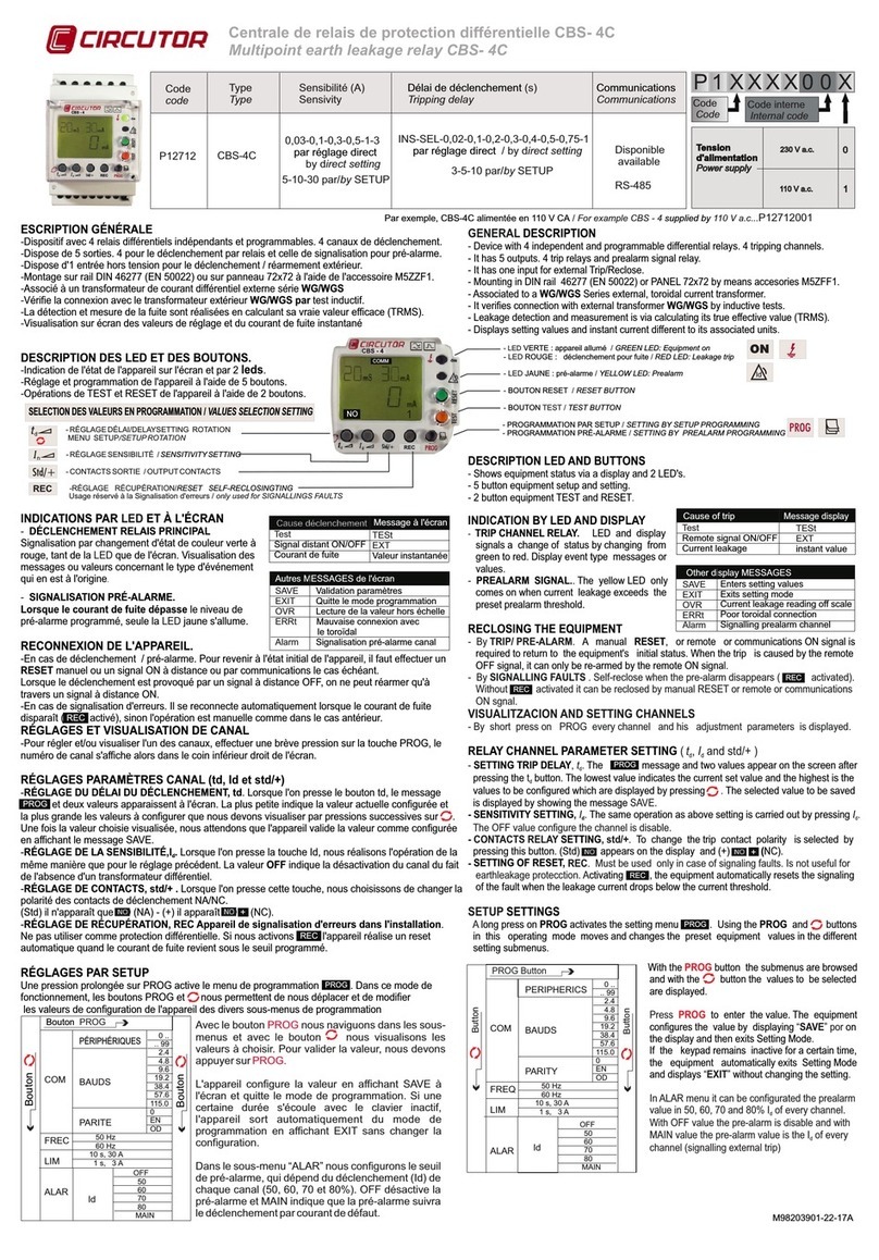
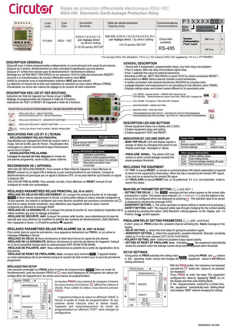
DESCRIPTION DES DIODES DEL ET DES BOUTONS POUSSOIRS / LEDS AND BUTTONS DESCRIPTIONS
- Indication de l'état de l'équipement par display et 2 diodes DEL.
- Réglage et programmation de l'équipement par 5 boutons poussoirs.
- TEST et RESET de l'équipement par 2 boutons poussoirs.
PROG
- RÉGLAGE RETARD / DELAY SETTING
- ROTATION MENU SETUP / SETUP ROTATION
AUTO
- - RÉGLAGE RESET PRÉALARME
RESET PREALARM SETTING
- RÉGLAGE SENSIBILITÉ
SENSITIVITY SETTING
- RÉGLAGE SÉCURITÉ
SAFETY SETTING
Autres MESSAGES par display
SAVE
EXIT
OVR
Valide les valeurs de configuration
Sort hors du mode de programmation
Lecture de la valeur hors échelle
Cause du déclenchement Message display
Test
Signal distant ON/OFF
Courant de fuite
TESt
EXT
valeur instantanée
- LED VERDE: Equipo encendido /
- LED ROJO: Disparo por fuga /
- LED Prealarma /
- PULSADOR RESET /
- PULSADOR TEST /
GREEN LED: Equipment on
RED LED: Leakage trip
LED: Prealarm
RESET BUTTON
TEST BUTTON
- PROGRAMACIÓN POR SETUP
- PROGRAMACIÓN PREALARMA
SETTING BY SETUP PROGRAMMING
SETTING BY PREALARM PROGRAMMING
Id
Cause of trip
Message display
Test
Remote signal ON/OFF
Current leakage
TESt
EXT
instant value
Other display MESSAGES
SAVE
EXIT
OVR
Enters setting values
Exits setting mode
Current leakage reading off scale
button
PROG button
FREQ
LIM
button
50 Hz
60 Hz
10 s, 30 A
1 s, 3 A
mS mA
mA
PROG
mS mA
mA
PROG
mSmA
mA
PROG
mSmA
mA
PROG
mS mA
mA
PROG
mS mA
mA
PROG
td
td
PROG
PROG
PROG
PROG
td
td
td
td
PROG
PROG
SAUVEGARDER MODIFICATIONS
SAVE CHANGES
QUITTER SETUP
EXIT SETUP
MENU SETUP / SETUP MENU
REC
+
PROG
INDICATIONS PAR DEL ET DISPLAY
- DÉCLENCHEMENT RELAIS PRINCIPAL.
Signalisation pour un changement d'état de couleur
verte à rouge, tant de DEL que du display. Les
messages ou les valeurs concernant le type
d'événement qui le produit, sont affichés..
- SIGNALISATION PRÉALARME. Lorsque le
courant de fuite dépasse le seuil de la préalarme
programmée, seul la diode DEL est allumée.
RECONNEXION DE L'ÉQUIPEMENT
- Par DÉCLENCHEMENT. Pour revenir à l'état initial de l'équipement, il faut réaliser un
RESET manuel ou un signal de réarmement externe. Le déclenchement forcé par signal
externe ne peut être réarmé que par signal externe de réarmement.
- Par PRÉALARME. Pour annuler cet état, il faut réaliser un RESET manuel s'il est
configuré en mode non automatique.
RÉGLAGES PARAMÈTRES RELAIS PRINCIPAL ( t, I et std/+ )
d d
- RÉGLAGE DU RETARD DE DÉCLENCHEMENT, t . En appuyant sur la touche tle
d d
message et deux valeurs apparaissent sur l'écran Le plus petit indique la valeur
actuelle configurée et le plus grand les valeurs à configurer que nous devons afficher en
appuyant sur . Une fois la valeur choisie affichée, on attend que l'équipement valide la
valeur comme étant configurée en montrant le message de SAVE.
- RÉGLAGE DE LA SENSIBILITÉ, I. En appuyant sur la touche I nous réalisons
dd
l'opération avec le même modus operandi que le réglage précédent.
- RÉGLAGE DE SÉCURITÉ, std/+ . En appuyant sur cette touche, nous sélectionnons le
type de sécurité que nous voulons en variant la polarité des contacts de déclenchement. Dans
le cas de (Std) Standard, rien n'apparaît sur l'écran, pour (+) Positive, le symbole apparaît .
RÉGLAGES PARAMÈTRES RELAIS PRÉALARME ( t, I, std/+ et Auto)
d d
La préalarme comprend deux relais simples, un NC et un autre NA. Pour programmer la
préalarme, une impulsion courte en PROG est réalisée, activant le message Alarm sur le display.
- RÉGLAGE DU RETARD, tnous sélectionnons le retard de temps en donnant le signal
d
de préalarme.
- RÉGLAGE DE LA SENSIBILITÉ, I nous sélectionnons le seuil de préalarme de
d
l'équipement. Indiquant en % la sensibilité choisie sur le canal principal (OFF-50-60-70-80-MAIN).
- RÉGLAGE DE POLARITÉ, std/+ . Nous sélectionnons la polarité de la sortie de
signalisation de la préalarme.
- RÉGLAGE DE RESET DE PRÉALARME, Auto. En activant l'équipement réalise
un reset de la préalarme sous une forme automatique lorsque le courant de fuite est à
nouveau en dessous du seuil de préalarme programmé.
.
RÉGLAGES PAR SETUP
Avec une impulsion longue sur PROG, nous activons le menu de programmation .
Dans ce mode de fonctionnement avec les boutons poussoirs PROG et nous nous
déplacerons en variant les valeurs de configuration de l'équipement dans les différents sous-
menus de programmation.
With the button the submenus are browse
and with the button the values to be selected are
displayed to enter the value. The
equipment configures the value by displaying
on the display and then exits Setting Mode. If
the keypad remains inactive for a certain time, the
equipment automatically exits Setting Mode and
displays without changing the setting
. Press
“SAVE”
“EXIT” .
PROG
PROG
Accessoires / Accesories
BORNES
ENFICHABLES
PLUG IN
CONNECTORS

This manual suits for next models

1

Other Circutor Relay manuals

Circutor RAGK-0.3 User manual

Circutor

Circutor RAGK-0.3 User manual

Circutor CBS-4 Series User manual

Circutor

Circutor CBS-4 Series User manual

Circutor RGU-10 MT User manual

Circutor

Circutor RGU-10 MT User manual

Circutor RGU-10C User manual

Circutor

Circutor RGU-10C User manual

Circutor RGE Series User manual

Circutor

Circutor RGE Series User manual

Circutor RGU-2 User manual

Circutor

Circutor RGU-2 User manual

Circutor RGU-10 MT User manual

Circutor

Circutor RGU-10 MT User manual

Circutor Master-Slave User manual

Circutor

Circutor Master-Slave User manual

Circutor RGU-10 User manual

Circutor

Circutor RGU-10 User manual

Circutor P24457 User manual

Circutor

Circutor P24457 User manual

Circutor CBS-4C-NC User manual

Circutor

Circutor CBS-4C-NC User manual

Circutor RGU-10 User manual

Circutor

Circutor RGU-10 User manual

Circutor RGU-10C User manual

Circutor

Circutor RGU-10C User manual

Circutor CBS-4 Series User manual

Circutor

Circutor CBS-4 Series User manual

Circutor RGU-10C User manual

Circutor

Circutor RGU-10C User manual

Circutor RGU-10 RAL User manual

Circutor

Circutor RGU-10 RAL User manual

Circutor CBS-400B User manual

Circutor

Circutor CBS-400B User manual

Circutor RGU-100A User manual

Circutor

Circutor RGU-100A User manual

Circutor CBS-4C User manual

Circutor

Circutor CBS-4C User manual

Circutor RGU-10C User manual

Circutor

Circutor RGU-10C User manual

Circutor RGU-10C User manual

Circutor

Circutor RGU-10C User manual

Circutor WRU-10 RAL User manual

Circutor

Circutor WRU-10 RAL User manual

Circutor RGU-10 MT User manual

Circutor

Circutor RGU-10 MT User manual

Circutor RGU-10 User manual

Circutor

Circutor RGU-10 User manual

Popular Relay manuals by other brands

Crouzet MNS quick start guide

Crouzet

Crouzet MNS quick start guide

Pilz PNOZ XV3.1 operating manual

Pilz

Pilz PNOZ XV3.1 operating manual

Savant CLI-REL1AUX1 Quick reference guide

Savant

Savant CLI-REL1AUX1 Quick reference guide

F&F BIS-410-24V manual

F&F

F&F BIS-410-24V manual

Siemens SIRIUS 3RR2443-1AA40 operating instructions

Siemens

Siemens SIRIUS 3RR2443-1AA40 operating instructions

Siemens Ohmega 406 7SG16 manual

Siemens

Siemens Ohmega 406 7SG16 manual

Teka ELOBAU 462 121.E1.1 operating manual

Teka

Teka ELOBAU 462 121.E1.1 operating manual

Reznor CL31 Installation

Reznor

Reznor CL31 Installation

KAEL Muhendislik Elektronik VARkombi-12-PC-TFT-OG-SOLAR manual

KAEL Muhendislik Elektronik

KAEL Muhendislik Elektronik VARkombi-12-PC-TFT-OG-SOLAR manual

Devantech ESP32LR42 user manual

Devantech

Devantech ESP32LR42 user manual

Schmalz EVE-TR 4 DC operating instructions

Schmalz

Schmalz EVE-TR 4 DC operating instructions

System Sensor R-10T Installation and maintenance instructions

System Sensor

System Sensor R-10T Installation and maintenance instructions

GE IAC instructions

GE

GE IAC instructions

Siemens SIRIUS 3ZX1012-0RU11-1DA1 operating instructions

Siemens

Siemens SIRIUS 3ZX1012-0RU11-1DA1 operating instructions

SVS SHR-12 X4 manual

SVS

SVS SHR-12 X4 manual

Siemens siprotec SJ62 user manual

Siemens

Siemens siprotec SJ62 user manual

GE IAV51A instructions

GE

GE IAV51A instructions

ABB RELION REF615R manual

ABB

ABB RELION REF615R manual

manuals.online logo
manuals.online logoBrands
  • About & Mission
  • Contact us
  • Privacy Policy
  • Terms and Conditions

Copyright 2025 Manuals.Online. All Rights Reserved.