Spellman 205B-05R Supplement

Artisan Technology Group is your source for quality
new and certied-used/pre-owned equipment
• FAST SHIPPING AND
DELIVERY
• TENS OF THOUSANDS OF
IN-STOCK ITEMS
• EQUIPMENT DEMOS
• HUNDREDS OF
MANUFACTURERS
SUPPORTED
• LEASING/MONTHLY
RENTALS
• ITAR CERTIFIED
SECURE ASSET SOLUTIONS
SERVICE CENTER REPAIRS
Experienced engineers and technicians on staff
at our full-service, in-house repair center
WE BUY USED EQUIPMENT
Sell your excess, underutilized, and idle used equipment
We also offer credit for buy-backs and trade-ins
www.artisantg.com/WeBuyEquipment
REMOTE INSPECTION
Remotely inspect equipment before purchasing with
our interactive website at www.instraview.com
LOOKING FOR MORE INFORMATION?
Visit us on the web at www.artisantg.com for more
information on price quotations, drivers, technical
specications, manuals, and documentation
Contact us: (888) 88-SOURCE | sales@artisantg.com | www.artisantg.com
SM
View
Instra

Spellman High Voltage Electronics Corporation One Commerce Park,
Valhalla, NY 10595, (914) 686-3600, Fax: (914) 686-2870
SPELLMAN
Valhalla, NY, USA CONFIGURATION SWITCH IS SET FOR
MODEL 205B-05R.
PLEASE REFER TO PAGES 5 TO SET
SWITCH FOR YOUR UNIT.
INSTALLATION
AND
OPERATING
INSTRUCTION MANUAL
MODEL
200-C488
WARNING
THIS UNIT CONTROLS HAZARDOUS VOLTAGES. DO NOT APPLY
INPUT POWER UNLESS ADEQUATE GROUNDING IS PROVIDED
TO THE POWER SUPPLY AND THE HIGH VOLTAGE
OUTPUT HAS BEEN PROPERLY CONNECTED.
WARRANTY
Spellman High Voltage warrants this instrument to be free from defects in material and workmanship for a
period of one year from date of shipment. This warranty does not apply to equipment that has been
subjected to misuse or which has been repaired or altered in any way by the user. Spellman High Voltage
is responsible only for the cost of material and labor to repair or replace, FOB our factory, products proved
to be defective during the warranty period. We are no liable for consequential damages incurred due to the
failure of this equipment. No other warranty is expressed or implied. All products returned under warranty
must be shipped prepaid to the factory with documentation describing the malfunction noted. It is
recommended that the factory be notified and a Return Authorization Number obtained prior to shipment.
The equipment will be evaluated, then repaired or replaced, promptly returned if the warranty claims are
found to be substantiated. A nominal service charge will be made for any unsubstantiated claims. Include
the Spellman Model and Serial number in all correspondence with the factory.
THE DATA CONTAINED IN THIS MANUAL IS SUBJECT TO CHANGE WITHOUT NOTICE.
WRITTEN PERMISSION FROM SPELLMAN HIGH VOLTAGE IS REQUIRED PRIOR TO THE
REPRODUCTION OF ANY TECHNICAL DATA CONATINED IN THIS MANUAL.
Artisan Technology Group - Quality Instrumentation ... Guaranteed | (888) 88-SOURCE | www.artisantg.com

Spellman High Voltage Electronics Corporation One Commerce Park,
Valhalla, NY 10595, (914) 686-3600, Fax: (914) 686-2870
SECTION I INTRODUCTION/SPECIFICATIONS
1.0 SCOPE OF MANUAL
This manual is provided to assist the user in the installation and operation of the Spellman Model 200-C488
IEEE-488 interface for the Spellman Series 205A/210 high voltage power supplies. For the protection of
personnel and equipment, it is essential that this manual be thoroughly read prior to the installation and
application of power.
1.1 PURPOSE OF EQUIPMENT
The model 200-C488 greatly enhances the versatility of the Series205A/210 high voltage power supplies.
IEEE-488 controllable devices are now found in many different fields, such as engineering and science,
information processing, medicine, industrial process control as well as research and development.
1.2 DESCRIPTION
The 200-C488 is an interface that allows a GPIB controller to program and monitor a Series 205A/210 high
voltage power supply. In addition to duplicating the front panel operation, the 200-C488 provides the user
with a number of additional functions such as programmable overload detection and response. The GPIB
controller may send commands to the interface that programs the output and set other user programmable
parameters, and read back output meter readings and status information.
The 200-C488 is a single 19inch rack mountable unit that is 3-1/2 inches high. It is AC powered (115/230
Vac switch selectable) and connects to the high voltage power supply via a single seven-conductor cable.
1.3 ELECTRICAL SPECIFICATIONS
Input Power: 115/230Vac +10%, 50 – 60 Hz
Interface: A seven conductor cable is used to connect the 200-C488 and the 205A/210
Series power supply. The user is supplied with the mating connectors and must
solder the conductors in the length that is required. The pin A’s of the two
mating connector are connected, the pin B’s are connected, and likewise for
each of the seven pins A through H.
PIN: FUNCTION:
A -5Vdc reference from 250A/210
B 0 to –5Vdc programming signal to 205A/210
C Ground
D Current monitor signal from 205A/210
E Voltage monitor signal from 205A/210
F Reserved
H Reserved
Artisan Technology Group - Quality Instrumentation ... Guaranteed | (888) 88-SOURCE | www.artisantg.com

Spellman High Voltage Electronics Corporation One Commerce Park,
Valhalla, NY 10595, (914) 686-3600, Fax: (914) 686-2870
The user must provide the IEEE-488 cable, which is required to interface the
Model 200-C488 to the users GPIB network.
GIPB Functions: SH1 Source Handshake
AH1 Acceptor Handshake
T1 Talker
L1 Listener
SR1 Service Request
DT1 Device Trigger
Using these GPIB functions the GPIB controller may send ASCII command
strings to control and monitor the high voltage power supply.
Size: 19.0”W X 3.5”H X 9.5”D (483 X 83 X 242mm)
Weight: 10lbs (4.6kg)
SECTION II GENERAL DESCRIPTION
CAUTION- THE UNIT BEING CONTROLLED BY THE 200-C488 CAN STORE
HAZARDOUS VOLTAGE. COMPLETELY DISCHARGE HIGH VOLTAGE AT
REAR PANEL GROUND TERMINAL BEFORE ATTEMPTING REMOVAL OF
THE HIGH VOLTAGE CABLE.
2.1 INSTALLATION
The Model 200-C488 IEEE 488 interface can amount in a standard 19” rack.
2.2 INPUT POWER
Input AC line voltage required is 115/230 Vac + 10%, 50 – 60 Hz, single phase. The LINE VOLTAGE
selector switch on the rear panel selects either 115Vac operation.
2.3 PROGRAM CONTROL SWITCH
Before the Series 205A/210 may be used in a GPIB system, the power supply must be configured by setting
the power supply’s rear panel REMOTE/LOCAL control switch in the remote position.
2.4 GPIB ADRESS SWITCH
Located on the rear panel of the 200-C488 is an eight-position DIP switch. Every instrument on a GPIB
must have am unique bus address in the range 0 to 30, inclusive. The address is set with five switches A4
through A0, A4 the most significant bit and A0 the least significant bit. Bits A5 and A7 of the address
switch must remain at the logic zero state. Bit A6 control whether the 200-C488 will terminate character
strings with or without a carriage return and a linefeed. Figure 2.1 shows the switch orientation and bit
designations.
The GPIB address switch is only read on power- on. Therefore, when the address is to be changed, the unit
must be turned off and then back on.
Artisan Technology Group - Quality Instrumentation ... Guaranteed | (888) 88-SOURCE | www.artisantg.com

Spellman High Voltage Electronics Corporation One Commerce Park,
Valhalla, NY 10595, (914) 686-3600, Fax: (914) 686-2870
Artisan Technology Group - Quality Instrumentation ... Guaranteed | (888) 88-SOURCE | www.artisantg.com
Spellman High Voltage Electronics Corporation One Commerce Park,
Valhalla, NY 10595, (914) 686-3600, Fax: (914) 686-2870
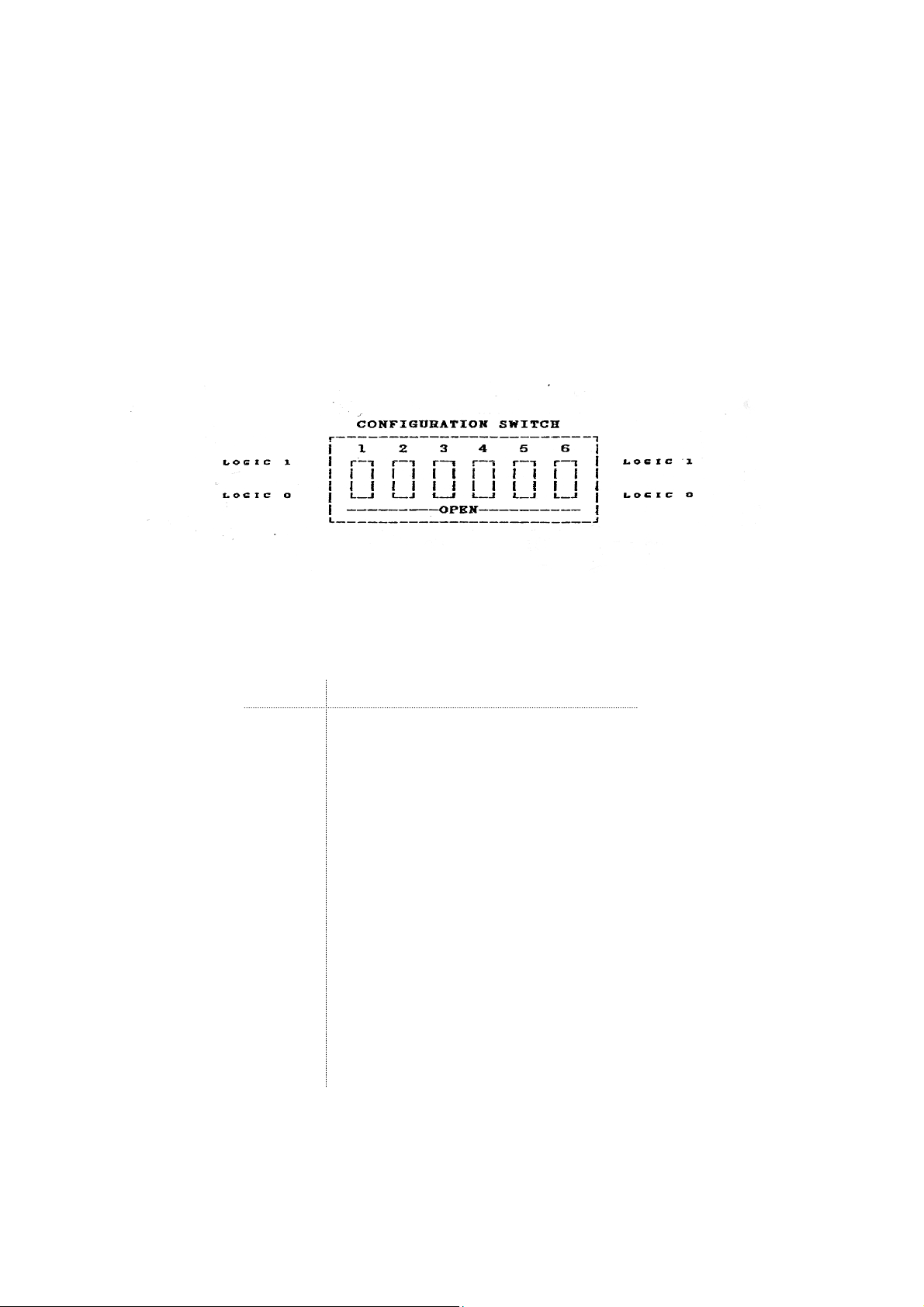
2.5 CONFIGURATION SWITCH
Since a 200-C488 interface may be used with any Spellman Series 205A/210 high voltage power supply,
the 200-c488 must be configured to implement the correct data formats for each supply. After removing
the top cover of the 200-C488, a six position DIP switch may be seen on the large printed circuit board.
Table 2.1 shows the correct setting for each power supply.
As with the GIPB switch the configuration switch is only at power-on and if it is to be changed, the unit
must be turned off and then back on, or reset. Figure 2.2 is a representation of the switch, as it would be
seen on the PCB.
FIGURE 2.2
Table 2.1
CONFIGURATION SWITCH SETTINGS BY MODEL
SWITCH POSITION
MODEL: 1 2 3 4 5 6
205A/B-01R 0 0 0 0 0 0
205A/B-03R 0 0 0 0 0 1
205A/B-05R 0 0 0 0 1 0
205A/B-10R 0 0 0 0 1 1
205A/B-20R 0 0 0 1 0 0
205A/B-30R 0 0 0 1 0 1
205A/B-50R 0 0 0 1 1 0
210-01R 0 0 0 1 1 1
210-01.5R 0 1 1 1 1 0
210-02R 0 1 0 0 0 0
210-03R 0 0 1 0 0 0
210-05R 0 0 1 0 0 1
210-10R 0 0 1 0 1 0
210-20R 0 0 1 0 1 1
210-30R 0 0 1 1 0 0
210-50R 0 0 1 1 0 1
210-75N/P 0 0 1 1 1 0
210-100N/P 0 0 1 1 1 1
Artisan Technology Group - Quality Instrumentation ... Guaranteed | (888) 88-SOURCE | www.artisantg.com

Spellman High Voltage Electronics Corporation One Commerce Park,
Valhalla, NY 10595, (914) 686-3600, Fax: (914) 686-2870
SECTION III GPIB OPERATION
CAUTION – THE UNIT BEING CONTROLLED BT THE 200-C488 CAN STORE
HAZARDOUS VOLTAGE. COMPLETELY DISCHARGE HIGH VOLTAGE AT
REAR PANEL GROUND TERMINAL BEFORE ATTEMPTING REMOVAL OF
THE HIGH VOLTAGE CABLE.
3.1 GPIB PROTOCOL
The 200-C488 implements the following GPIB Functions:
SH1 Source Handshake
AH1 Acceptor Handshake
T1 Basic Talker & Serial Poll
L1 Basic Listener
SR1 Service Request
DC1 Device Clear
DT1 Device Trigger
Using these GPIB functions, the GPIB controller may send ASCII command strings to control and monitor
the high voltage power supply.
3.1.1 DATA TRANSFER FUNCTIONS – SH1, AH1, T1, L1
SH1, AH1, T1, and L are data transfer functions, and normally transparent to the User. These functions
permit the communication between the GPIB controller and the Model 200-c488 interface.
3.1.2 SERVICE REQUEST FUNCTIONS – SR1
SR1 contains two sub-functions; Service Request and Serial Poll. The service request is the mechanism by
which the 200-C488 may interrupt the GPIB controller and the serial poll is how the GPIB controller may
read the status of the 200-C488.
3.1.2.1 SERVICE REQUEST
There are two conditions that will cause the 200-C488 to generate a service request; at power-on and during
user programmed overload detection. The meaning of the serial poll status byte that is read depends on the
condition that caused the service request. The power –on mode is true when the 200-C488 is first turned on
and before the GPIB controller sends a command to the interface. The overload detect mode is after the
GPIB control has sent its first command to the interface. Any service request may be ignored without
affecting operation of the interface or power supply.
3.1.2.2 SERIAL POLL
When the GPIOB controller executes a serial poll, the 200-C488 sends it one byte of status. As mentioned
above, the decoding of the status byte is dependent on when it is read. The FIGURE 3.1 below shows the
decoding of the power-on status byte, and FIGURE 3.2 shows the decoding of the ‘normal operation” (not
the power-on) status byte.
Artisan Technology Group - Quality Instrumentation ... Guaranteed | (888) 88-SOURCE | www.artisantg.com
Spellman High Voltage Electronics Corporation One Commerce Park,
Valhalla, NY 10595, (914) 686-3600, Fax: (914) 686-2870
FIGURE 3.1
At power –on before any command is sent, the status byte is:
Note that the MSB is logic 1 which identifies this byte as the status register contents at power on, prior to
the issuance of any command. IF the user does not do a serial poll at power on and sends any command,
the status byte obtained in response to a subsequent serial poll will appear as seen in FIGURE 3.2 below.
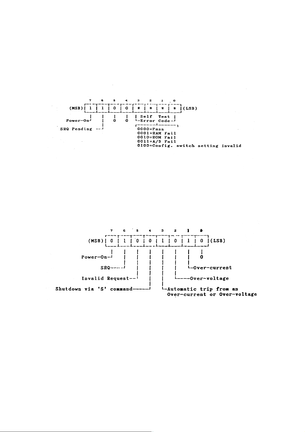
FIGURE 3.2
After first command the register looks like this:
Note that the MSB of this byte is logic 0 which identifies this byte as the status register contents following
the issuance of at least one command since power on.
When the SQR bit is logic 1, it means this status byte is in response to the first serial poll following the
issuance of an SRQ. If the SQR bit is logic 0, it means that the status byte obtained is one you have
previously examined and/or is not in response to a service request.
When the invalid request bit is logic 1, it means that you have issued a command the unit cannot recognize.
Normally this bit stays at logic 0.
Artisan Technology Group - Quality Instrumentation ... Guaranteed | (888) 88-SOURCE | www.artisantg.com

Spellman High Voltage Electronics Corporation One Commerce Park,
Valhalla, NY 10595, (914) 686-3600, Fax: (914) 686-2870
A logic 1 in any of the five remaining bits indicates a “true” state of that parameter. A logic 0 indicates a
“false”.
EXAMPLE BIT PATTERN
BIT MEANING:
7 0: You are looking at the status byte after at least one command
6 1: You are making your first examination of this byte after the unit’s issuance of an SQR.
5 0: The previous command was valid.
4 0: You have not shut down the unit with a “S” command.
3 1: You did get a trip (a turning off) of high voltage in response to either a voltage or current
overload
2 0: The supply is not in voltage overload.
1 1: The supply is in current overload.
0 0: This bit of this status byte is always logic 0.
3.1.3 DEVIC CLEAR FUNCTION – DCI
The device clear and selective device clear GPIB functions set the high voltage output to 0 volts regardless
of the current voltage program. They perform to 0 volts regardless of the current voltage program. They
perform identically to the user command ‘S’ explained in section 3.2.4.
3.1.4 DEVICE TRIGGER FUNCTION – DTI
The device trigger function is used to update the previously programmed parameters. It performs the same
as the user command ‘G’, explained in section 3.2.3, and has the additional capability of triggering
numerous bus instruments simultaneously.
3.2 USER COMMANDS
The 200-C-488 recognizes a number off commands, in the form of ASCII strings. These commands
execute the various programming and monitoring functions enabling the user to control a Spellman Series
20A/210 high voltage power supply. These commands are:
♦Programming the Output Voltage (‘P’)
♦Setting Output Voltage and Current Limits (‘L’)
♦Shutting off the High Voltage Output (‘S’)
♦Restoring the High Voltage Output (‘R’)
♦Selecting the Overload Shutdown Response (‘C’)
♦Selecting the Overload Service Request Response (‘N’)
♦Triggering Meter Readings of the Output (‘T’)
Artisan Technology Group - Quality Instrumentation ... Guaranteed | (888) 88-SOURCE | www.artisantg.com

Spellman High Voltage Electronics Corporation One Commerce Park,
Valhalla, NY 10595, (914) 686-3600, Fax: (914) 686-2870
NOTE: All characters in the ASCII command string must be in UPPER CASE ONLY. The
interface will not recognize lower case characters.
The syntax of the commands is fairly rigid, especially the format of the numeric voltage and current strings.
Table 3.0 shows the numeric formats for programming the Model 200-C488 high voltage power supply.
TABLE 3. 0
NUMERIC FORMATS FOR PROGRAM, LIMIT & METER COMMANDS:
FORMAT CURENTS
MODEL VOLTAGE CURRENT UNITS
205A/B-01R x.xxxx xx.xxx M
205A/B-03R x.xxxx xx.xxx M
205A/B-05R x.xxxx x.xxxx M
205A/B-10R xx.xxx x.xxxx M
205A/B-20R xx.xxx x.xxxx M
205A/B-30R xx.xxx xxx.xx U
205A/B-50R xx.xxx xxx.xx U
210-01R x.xxxx xxx.xx M
210-01.5R x.xxxx xxx.xx M
210-02R x.xxxx xxx.xx M
210-03R x.xxxx xx.xxx M
210-05R x.xxxx xx.xxx M
210-10R xx.xxx xx.xxx M
210-20R xx.xxx x.xxxx M
210-30R xx.xxx x.xxxx M
210-50R xx.xxx x.xxxx M
210-75N/P xx.xxx x.xxxx M
210-100N/P xxx.xx x.xxxx M
3.2.1 PROGRAMMING THE HIGH VOLTAGE OUTPUT (‘P’)
This command allows the user to set the output voltage of the power supply. The syntax is:
‘P {numeric string} K’
Where {numeric string} is an ASCII string of five digits with a decimal point. The resolution of the
programming value (and monitors) is five digits. Since a Series 205A/210 power supply may each have a
different output rating, the programming command will have different formats. In general, the program
command will be one of those shown below:
Px.xxxxK
Pxx.xxxK
The numeric format (x.xxxx or xx.xxx) will depend on the unit being controlled. This numeric format must
be packed with zeros to fully fill five digits and decimal point. Therefore, if a 1kV power supply, with
format x.xxxx is to be programmed to 230 volts, the command will be P0.2300K. If a 20kV supply is to be
programmed to 11,500 volts, the command will be P11.500K.
The actual high voltage output will not change after the program command until the 200-C488 receives a
device trigger bus command or the ‘G’ command string (see sections 3.1.4 and 3.2.3).
3.2.2 SETTING THE OUTPUT LIMITS (‘L’)
The 200-C488 monitors the power supply output voltage and current to detect if the parameters exceed the
user thresholds. Each parameter (voltage and current) is monitored at the rate of once per second. The user
may set threshold limits that when exceeded will invoke the user programmed shutdown and service
Artisan Technology Group - Quality Instrumentation ... Guaranteed | (888) 88-SOURCE | www.artisantg.com

Spellman High Voltage Electronics Corporation One Commerce Park,
Valhalla, NY 10595, (914) 686-3600, Fax: (914) 686-2870
request responses (see section 3.2.6 and 3.2.7). The limit commands start with an ‘L’ followed by a
numeric string that represents the threshold value, then followed by a character that distinguishes between
the voltage and current limits. A’K’ indicates a kilovolt limit and an ‘M’ or ‘U’ indicates a milliamp or
microamp limit respectively. The syntax is:
‘L {numeric string} K’ Kilovolt Limit
‘L {numeric string} M’ Milliamp Limit, or
‘L {numeric string} U’ Microamp Limit
where {numeric string} is as described Table 3.0. It is very likely that the numeric formats for the voltage
and current will be different.
The voltage limit command uses the same numerical format as the programming command, but starts will
an ‘L’. Below are some examples:
Lx.xxxxK L0.6523K limits to 652.3V
Lxx.xxxK L29.400K limits to 29.4kV
The output current limit threshold may also be set. When this value is exceeded the 200-C488 will respond
as programmed by the user. This command also requires a strict numerical format. Since it represents
output current, the decimal point, may be in a different position than the voltage format. Below are some
examples of the current limit command.
Lxx.xxxM L12.000M limits to 12mA
Lx.xxxxM L1.0500M limits to 1.05mA
Lxxx.xxU L473.50U limits to 473.5uA
The actual limit values will not change after the limit command until the 200-C488 receives a device
trigger bus command or the ‘G’ command string (see sections 3.1.4 and 3.2.3).
3.2.3 ENTERING THE CURRENT PROGRAMMING & LIMIT VALUES (‘G’)
After executing a programming or limit command, these new values will not be used immediately. The
user must execute the ‘G’ command that will update the current values with the new ones. Therefore, if the
output is currently programmed to 1kV and the user executes a program command such as ‘P1.5000K, the
output will not change until the ‘G’ command is executed. The syntax is:
‘G’ the single ASCII character
When timing is not important, the ‘G’ may be appended to the programming or limiting command as
shown below.
Pxx.xxxKG
lx.xxxxMG
3.2.4 SHUTTING THE HIGH VOLTAGE OUTPUT (‘R’)
The high voltage output may be turned back on to the currently active programming level after it was shut
off by a user command ‘S’ or a trip due to overload. The syntax. The syntax is:
‘S’ the single ASCII character
This is the same effect as executing the device clear bus command.
3.2.5 RESTORING THE HIGH VOLTAGE OUTPUT (‘R’)
The high voltage output will return to the value that was programmed before the shutdown. If the output is
off because of an overload trip, the cause of the overload should be corrected before restoring the output
voltage or the trip will occur again.
Artisan Technology Group - Quality Instrumentation ... Guaranteed | (888) 88-SOURCE | www.artisantg.com

Spellman High Voltage Electronics Corporation One Commerce Park,
Valhalla, NY 10595, (914) 686-3600, Fax: (914) 686-2870
3.2.6 SELECTING THE OVERLOAD TRIP RESPONSE (‘C’)
When the 200-C488 detects that the power supply has exceeded one of the user-programmed limits, it may
respond by shutting off the high voltage output, also known as tripping. The user may select that the power
supply be tripped for a voltage overload, a current overload, either a voltage or current overload, or neither.
The syntax is:
‘C {numeric}’
where {numeric} is the ASCII byte for 0, 1, 2, or 3 and:
C0 Enable the overvoltage and overcurrent control to shut down the power supply upon
detection of an output voltage or current above their respective limit setting(s).
C1 Enable the overvoltage control to shut down the power supply upon detection of an
output voltage above the voltage limit setting only.
C2 Enable the overcurrent control to shut down the power supply upon detection of an output
current above the current limit setting only.
C3 Disable the overvoltage control and overcurrent control.
3.2.7 SELECTING THE OVERLOAD SERVICE REQUEST RESPONSE (‘N’)
Just as the 200-C488 may be made to shut off the output during an overload, it may be may to generate a
service request to the GPIB controller. The syntax is:
“N {numeric}’
where {numeric} is the ASCII byte for 0, 1, 2, or 3 and:
N0 Enable SQR in response to an overvoltage or overcurrent detection.
N1 Enable SQR in response to an overvoltage detection only.
N2 Enable SQR in response to an overcurrent detection only.
N3 Disable SQR in response to an overvoltage or overcurrent detection.
When an SRQ is received, the user should execute a serial poll of the unit, the status byte will be the result
of the serial poll. Please note that overload enabling/disabling and service request choices operate
independently of each other.
3.2.8 TRIGGERING METER READINGS OF THE OUTOPUT (‘T’)
The 200-C-488 has the capability to perform meter readings of the power supply output voltage and
current. The user may trigger a reading of the output voltage, current or both. The syntax is:
‘T {numeric}’
where {numeric} is the ASCII byte for 0,1 or 2 and:
T0 Triggers a measurement of the output voltage and current.
T1 Triggers a measurement of the output voltage only.
T2 Triggers a measurement of the output current only.
Artisan Technology Group - Quality Instrumentation ... Guaranteed | (888) 88-SOURCE | www.artisantg.com

Spellman High Voltage Electronics Corporation One Commerce Park,
Valhalla, NY 10595, (914) 686-3600, Fax: (914) 686-2870
Since this is an ASCII string it may be printed directly to the CRT or printer. After receiving the ‘T’
command the 200-C488 will return a character string containing the output status (Normal, Tripped or
Shutdown) and the voltage and/or current readings in the same numerical format as is used to enter voltage
and current values. Below are the ‘T’ commands with representative measurement strings that would be
returned from the 200-C488.
T0 ‘N Vxx.xxxK Ix.xxxxM’
T1 ‘N Vx.xxxxK’
T2 ‘N Ixxx.xxU’
Where the ‘N’ in the string means the output is on. It may be replaced with an ‘S’ that means the output
was shutdown by user with an ‘Z’ command or device clear bus command, or a ‘T’ in that means the output
was tripped due to an overload detection where:
‘V’ in the string means voltage
‘I’ in the string means current
‘K’ in the string means kilovolts
‘M’ in the string means milliamps
‘U’ in the string means microamps
SECTION IV MAINTANENANCE
4.1 GENERAL
The 200-C488 interface should not require any maintenance or calibration. It is designed for
reliable, trouble free operation. If any question should arise, contact the Spellman Customer
Service Department for assistance or return authorization. Although adequate information is
provided in this manual, it is suggested that the unit be returned to the factory if service should
become necessary.
Artisan Technology Group - Quality Instrumentation ... Guaranteed | (888) 88-SOURCE | www.artisantg.com

Artisan Technology Group is your source for quality
new and certied-used/pre-owned equipment
• FAST SHIPPING AND
DELIVERY
• TENS OF THOUSANDS OF
IN-STOCK ITEMS
• EQUIPMENT DEMOS
• HUNDREDS OF
MANUFACTURERS
SUPPORTED
• LEASING/MONTHLY
RENTALS
• ITAR CERTIFIED
SECURE ASSET SOLUTIONS
SERVICE CENTER REPAIRS
Experienced engineers and technicians on staff
at our full-service, in-house repair center
WE BUY USED EQUIPMENT
Sell your excess, underutilized, and idle used equipment
We also offer credit for buy-backs and trade-ins
www.artisantg.com/WeBuyEquipment
REMOTE INSPECTION
Remotely inspect equipment before purchasing with
our interactive website at www.instraview.com
LOOKING FOR MORE INFORMATION?
Visit us on the web at www.artisantg.com for more
information on price quotations, drivers, technical
specications, manuals, and documentation
Contact us: (888) 88-SOURCE | sales@artisantg.com | www.artisantg.com
SM
View
Instra
Table of contents
Popular Recording Equipment manuals by other brands

Korg
Korg MPS-10 owner's manual

Vertiv
Vertiv LIEBERT BATTERY INTERFACE BOX UPSBIBX Product specification/installation sheet

Agilent Technologies
Agilent Technologies 82357B quick start guide

Pronomic
Pronomic PP-10-USB quick start guide

Evinox
Evinox ModuSat XR ECO CHHC manual

Pneuance Audio
Pneuance Audio Pneupod NP-1 Setup Instruction


