SperryMarine NAVIKNOT SRD 500 A Manual
Northrop Grumman Sperry Marine B.V.
Woltmanstr. 19 • D-20097 • Hamburg, Germany
Tel.: +49-40-299 00-0 • Fax: +49-40-299 00-146 • E-mail: service.eu@sperry.ngc.com
Operation, Installation and Service Manual
Original Documentation / Keep for Future Reference
MASTER
SRD 500A
N.MILES
DAILY
TOTAL
kn
1234.56
123456.7
12
8
.
0
0
.12
NO ALERTS
ENTER
ACK
MUTE MENU MASTER
DIM
-
DIM
+
MASTER
SRD 500A
N.MILES
DAILY
TOTAL
kn
1234.56
123456.7
12 8.0
0.12
NO ALERTS
NAVIKNOT
Speed Log
DBT 23.4 M
DIM
+
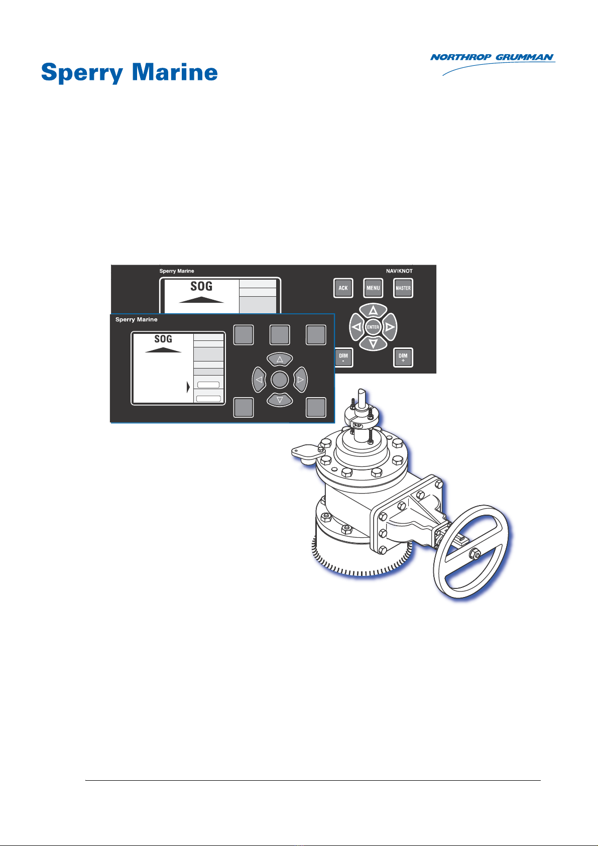
NAVIKNOT SRD 500 A
Dual-Axis Doppler Speed Log System
with Gate Valve Transducer
056361/F, 5003-0128-06, 15 Aug 2018

056361/F NAVIKNOT SRD 500 A
© 2018 Northrop Grumman Sperry Marine B.V.
This document and the information herein is the intellectual property of Northrop Grumman
Sperry Marine B.V. [NGSM BV] and its associate companies and may not be copied, reproduced
or translated without the express permission of NGSM BV.
Specifications were correct at time of press but may be varied in accordance with NGSM BV’s
policy of continuous product development.
Any technical content should be verified with NGSM BV.
Sperry Marine, with major engineering and support offices in New Malden, England, and
Hamburg, Germany, is part of the Northrop Grumman Navigation & Maritime Systems Division
N&MSD.ector.
Revision Record
Rev. Date Remarks
F 15 Aug 2018 updated version, applicable to EU, Rev. C, 2.100 and CDU, Rev. J, 1.100
software update, new CDU type 5001, Rev. F
E 20 Sep 2017 updated version, applicable to EU, Rev. C, 2.100 and CDU, Rev. J, 1.100
software update, new CDU type 5001, Rev. F
D 29 Jun 2016 updated version, maintenance procedures amended and added, sys-
tem equipment and spare parts amended, CDU software update proce-
dure amended
C 12 Aug 2015 updated version, regarding EU, and CDU software update, mainte-
nance menus amended, CAM interface settings and spare parts added
B 21 Nov 2012 initial release
A - unreleased, internal use only

SRD 500 A 056361/F
iii
Contents
Safety Instructions
Safety Notice Conventions......................................................................... ix
General Safety Information for the Operator ............................................ x
General Safety Information for Service Personnel................................. xiii
Chapter 1: Introduction
1.1 System Information .................................................................................. 1-1
Intended Use ...............................................................................................1-1
Not Intended Use.........................................................................................1-1
1.2 System Overview Transducer and Sea Chest......................................... 1-2
1.3 System Design and Main Features.......................................................... 1-4
NAVIKNOT Alert Management.....................................................................1-5
Data Outputs................................................................................................1-6
1.4 Operating Principle ................................................................................... 1-7
1.5 Technical Data............................................................................................ 1-8
System Specifications..................................................................................1-8
NAVIKNOT Electronics Unit, Type 5003 .......................................................1-9
Control and Display Units (CDU) ................................................................ 1-11
SRD 500 Doppler Electronics Unit (EU) Specification ................................1-14
Doppler Transducer Specification...............................................................1-15
1.6 Declaration of Conformity ...................................................................... 1-16
Chapter 2: Operation
2.1 Display and Operating Keys ..................................................................... 2-1
2.2 External control devices ........................................................................... 2-2
2.3 Power-up Sequence .................................................................................. 2-3
Operational Power-up Sequence ................................................................. 2-3
Power-up Sequence with Software Mismatch ............................................ 2-4
2.4 Display Indications.................................................................................... 2-6
Main Display Pages in Normal Operational Mode....................................... 2-6
Additional Operating Status Indications ...................................................... 2-8
2.5 Requesting Master Control ...................................................................... 2-9
2.6 Adjusting the display brightness........................................................... 2-10
2.7 Optional Functions.................................................................................. 2-11
Muting Alerts Remotely .............................................................................2-11
Resetting/Acknowledging a BNWAS Alarm ...............................................2-11
Activating Double-Ended Ferry Mode ........................................................2-11
External Dimming.......................................................................................2-12
2.8 Operating Menu ...................................................................................... 2-13
Entering and Quitting the Menu Mode ......................................................2-13
Navigating the Menu..................................................................................2-14
Selecting Parameter Settings.....................................................................2-15

056361/F SRD 500 A
iv
Editing Parameter Values .......................................................................... 2-15
Caption for Selecting and Editing .............................................................. 2-16
2.9 Manual Settings Menu ........................................................................... 2-17
Manual Settings – Overview ..................................................................... 2-18
Manual Settings – Parameters .................................................................. 2-19
2.10 User Setup ............................................................................................... 2-22
User Setup – Overview ............................................................................. 2-23
User Setup – Parameters .......................................................................... 2-25
Chapter 3: Alerts
3.1 Alert Management Preliminaries ............................................................. 3-1
3.2 Alert Indication .......................................................................................... 3-3
Audible Alert Indication ............................................................................... 3-3
Visual Alert Indication (ALR/ACK) ................................................................ 3-4
Visual Alert Indication (ALF-ALC-ARC/ACN)................................................. 3-6
3.3 Muting Alerts............................................................................................. 3-8
Local Alert Mute.......................................................................................... 3-8
External Alert Mute ..................................................................................... 3-9
3.4 Acknowledgement of Alerts (ALR/ACK) ............................................... 3-10
Acknowledgement of Alarms.....................................................................3-11
Acknowledgement of Warnings ................................................................ 3-15
3.5 Acknowledgement of Alerts (ALF-ALC-ARC/ACN)............................... 3-19
Acknowledgement of Warnings ................................................................ 3-20
Cautions .................................................................................................... 3-24
3.6 Serial Data Alert Management............................................................... 3-25
Alert Handling (ALR/ACK) .......................................................................... 3-25
Alert Handling (ALF-ALC-ARC/ACN) .......................................................... 3-26
3.7 NAVIKNOT Electronics Unit / CDU Alert Codes ................................... 3-27
Alerts (ALF-ALC-ARC/ACN) / Prop. BAM Alerts Active.............................. 3-29
Alerts (ALF-ALC-ARC/ACN) / Prop. BAM Alerts Inactive............................ 3-30
3.8 NAVIKNOT Electronics Unit / CDU Alert Codes ................................... 3-31
3.9 SRD 500 Doppler EU Fault Codes .......................................................... 3-33
Chapter 4: Scheduled Maintenance
4.1 Maintenance by Shipboard Personnel .................................................... 4-1
Electronic Components and CDU................................................................ 4-1
4.2 Maintenance by Service Personnel.......................................................... 4-2
Cleaning the Transducer Lens ..................................................................... 4-2
Gate Valve and Sea Chest Maintenance ..................................................... 4-4
3-Months Maintenance: Lubricating the Sea Valve ..................................... 4-5
Annual Maintenance: Cleaning the Transducer Lens .................................. 4-6
Five-Year Maintenance: Overhauling the Sea Chest.................................. 4-12
Transducer Drydock Maintenance ............................................................. 4-13

SRD 500 A 056361/F
v
Chapter 5: Sea Chest and Transducer Installation
5.1 Determining the Transducer Location ..................................................... 5-1
5.2 Installing the Sea Chest and Transducer................................................. 5-4
Installing the Spool Piece ............................................................................ 5-4
Installing the Sea Chest and Transducer in Drydock ................................... 5-6
Installing the Sea Chest without Transducer in Drydock............................5-12
Chapter 6: Electronics Unit and CDU Installation
6.1 Mechanical Installation ............................................................................ 6-1
NAVIKNOT Electronics Unit......................................................................... 6-1
SRD 500 Doppler EU .................................................................................. 6-1
Control and Display Units............................................................................ 6-2
6.2 Electrical Installation ................................................................................ 6-3
Wiring Up the System................................................................................. 6-3
Grounding ................................................................................................... 6-4
Configuring the CDU(s) ............................................................................... 6-4
Configuring System Parameters ................................................................. 6-8
Copying System Parameters....................................................................... 6-8
SRD 500 Doppler EU Post-Installation Functional Checks .......................... 6-9
Chapter 7: System Configuration
7.1 Initial System Configuration .................................................................... 7-1
7.2 Service Setup Menu.................................................................................. 7-2
Setup Access Code..................................................................................... 7-2
Service-Setup – Overview ........................................................................... 7-3
Service Setup – Description of Parameters ................................................ 7-9
Chapter 8: SRD 500 Doppler EU Configuration
8.1 SRD 500 Doppler EU configuration with BBTalk .................................... 8-1
Applying Approved Changes to the Default Configuration.......................... 8-1
8.2 SRD 500 Doppler EU Maintenance Mode ............................................... 8-2
8.3 Maintenance Mode – Main Menu ............................................................ 8-5
Maintenance Menu Overview..................................................................... 8-6
8.4 Maintenance Menu – Low-Level Commands ......................................... 8-9
Chapter 9: Doppler Transducer Calibration
9.1 Transducer Rotational Offset Correction................................................. 9-1
Manual Transducer Rotation........................................................................ 9-1
Automatic Transducer Rotation using Ground Speed ................................. 9-2
9.2 Ground and Water Speed Calibration ..................................................... 9-3
Speed Calibration Trial Runs........................................................................ 9-3
Entering the Calibration Values ................................................................... 9-6

056361/F SRD 500 A
vi
Chapter 10: Troubleshooting
10.1 General Troubleshooting Approach....................................................... 10-1
Environmental Factors affecting Operation ............................................... 10-1
SRD 500 Doppler EU Faults ...................................................................... 10-2
Unit Level Fault Isolation ........................................................................... 10-3
SRD 500 Doppler EU Fault Isolation.......................................................... 10-4
Transducer Fault Isolation.......................................................................... 10-4
10.2 NAVIKNOT EU and CDU(s) Fault Isolation ............................................ 10-6
Basic check instructions ............................................................................ 10-6
Location of Parts on the NAVIKNOT Electronics Unit PCB........................ 10-7
Exchangeable Components....................................................................... 10-8
Terminal Boards and Connectors............................................................... 10-8
Diagnostic LEDs ........................................................................................ 10-9
10.3 Maintenance Menu 1 ............................................................................ 10-10
Maintenance Menu 1 – Overview ............................................................10-11
Maintenance Menu 1 – Parameters .........................................................10-13
10.4 Maintenance Menu 2 ............................................................................ 10-15
Maintenance Menu 2 – Overview ............................................................10-16
Maintenance Menu 2 – Parameters .........................................................10-18
Chapter 11: Troubleshooting – Autotest Program
11.1 Executing the Automatic Test Sequence .............................................. 11-1
11.2 Executing Single Tests............................................................................ 11-4
Launching BBTalk from Autotest................................................................11-6
Quitting Autotest........................................................................................11-6
11.3 Summary of Single Test Options........................................................... 11-7
11.4 Other Troubleshooting Procedures...................................................... 11-25
Relative Temperature Test ........................................................................11-25
Troubleshooting if Transducer shows Ringing ..........................................11-26
Chapter 12: Corrective Maintenance – Transducer
12.1 Replacing the Transducer ....................................................................... 12-1
Materials and Tools Required .................................................................... 12-1
Removing the Existing Transducer ............................................................ 12-2
Installing the Replacement Transducer ..................................................... 12-5
Chapter 13: Corrective Maintenance – EU and CDU
13.1 Software Update Preliminaries .............................................................. 13-1
CDU SW Version Check ............................................................................ 13-2
NAVIKNOT Electronics Unit SW Version Check ........................................ 13-3
13.2 Updating the CDU Software via SUSI................................................... 13-4
Update Procedure ..................................................................................... 13-5
13.3 Updating the EU Software with a Flashboard ................................... 13-11
Exchanging the Flashboard ......................................................................13-11
13.4 Updating the EU Software via SUSI ................................................... 13-14
Update Procedure ................................................................................... 13-15

SRD 500 A 056361/F
vii
13.5 SRD 500 Doppler EU Update................................................................ 13-21
Downloading Firmware into the SRD 500 Doppler EU ............................13-21
Chapter 14: SRD 500 Doppler EU Utility Software
14.1 Installing the SRD 500 Doppler EU Utility Software ........................... 14-2
14.2 The BBTalk Program................................................................................ 14-3
Launching BBTalk .......................................................................................14-4
BBTalk Commands.....................................................................................14-6
14.3 The Autotest Program ............................................................................ 14-7
Required Test Equipment...........................................................................14-7
Setting Up the Hardware for Autotest .......................................................14-8
Launching Autotest ....................................................................................14-8
14.4 Monitor Program................................................................................... 14-10
Monitoring System Performance in Real-Time.........................................14-12
Chapter 15: Docking Information Display
15.1 Using DIB10 Display with the SRD 500 A System................................ 15-1
15.2 Input Data Sources ................................................................................. 15-2
15.3 Display Indications.................................................................................. 15-2
15.4 Operating Key Pad .................................................................................. 15-3
15.5 Display Setup .......................................................................................... 15-3
15.6 Initial Configuration ................................................................................ 15-5
Chapter 16: Spare Parts
Exchangeable Components .......................................................................16-1
Abbreviations
Appendix
A Setup and Configuration Tables
B Drawings

056361/F SRD 500 A
viii
SRD 500 A 056361/F
ix
Safety Instructions
Safety Notice Conventions
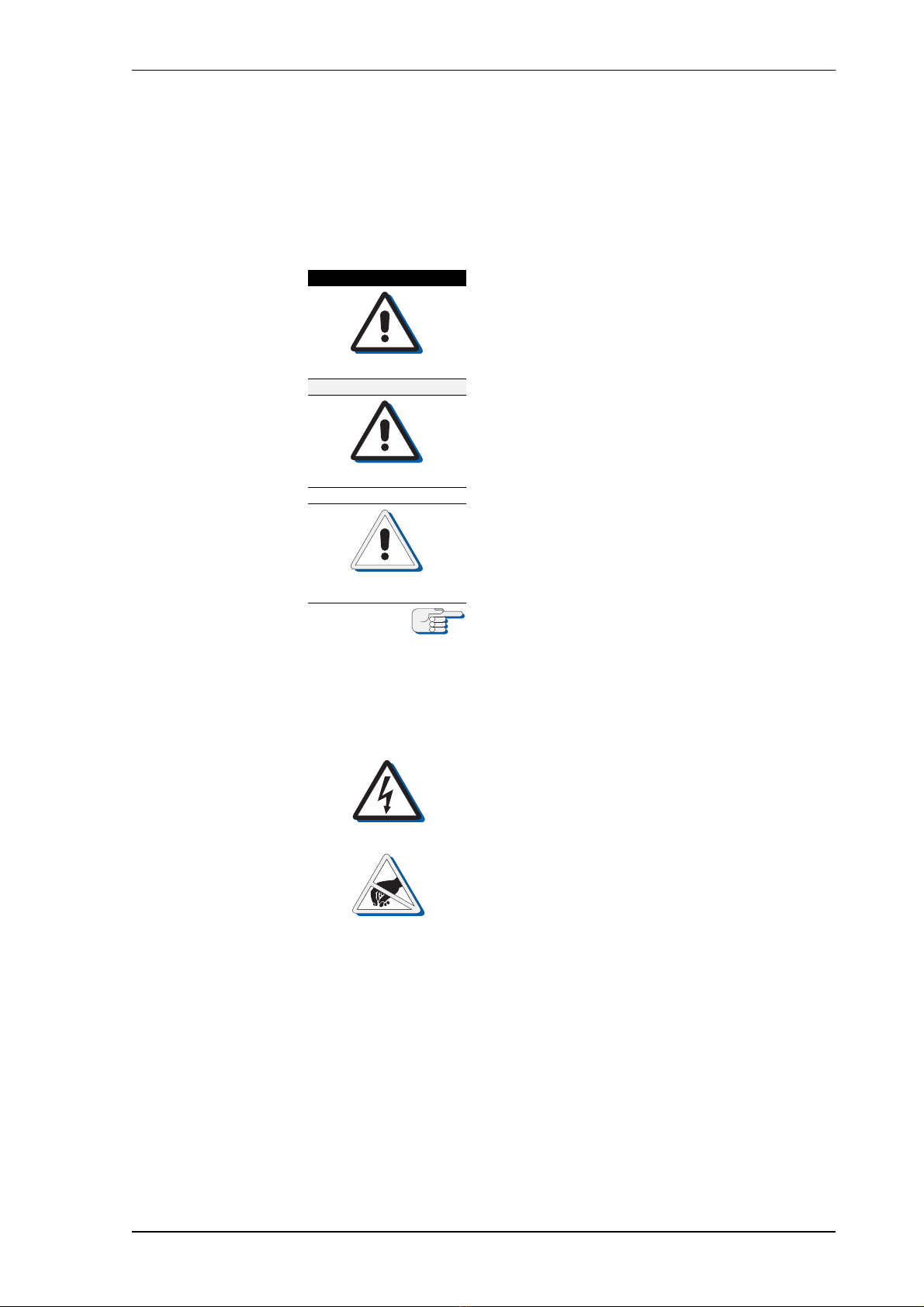
The following safety notice conventions apply throughout this manual:
DANGER
A Danger notice contains an operating or main-
tenance procedure, practice, condition, state-
ment, etc., which, if not strictly observed, will
result in injury or death of personnel.
WARNING
A Warning notice contains an operating or
maintenance procedure, practice, condition,
statement, etc., which, if not strictly observed,
could result in injury or death of personnel.
CAUTION
A Caution notice contains an operating or main-
tenance procedure, practice, condition, state-
ment, etc., which, if not strictly observed, could
result in damage to, or destruction of equip-
ment.
Note
A Note contains an essential operating or main-
tenance procedure, condition or statement,
which is considered important enough to be
highlighted.
Special safety symbols may be used in this
manual to indicate:
Risk of electrical shock.
Used in conjunction with a Danger or Warning
notice.
Electronic components sensitive to electrostatic
discharge.
Used in conjunction with a Caution notice.

056361/F SRD 500 A
x
General Safety Information for the Operator
WARNING
Risk of misusage
Before using the SRD 500 A, operators must be appropriately trained
and familiar with all operating procedures and safety instructions con-
tained in this manual. The manual is to be completely read before the
first usage of the SRD 500 A system.
Keep all system manuals in a well-known, readily available location.
CAUTION
Invalid speed and distance information in “MAN” mode of operation
in case of failure of the Doppler transducer the SRD 500 A does not pro-
vide valid speed and distance information and the system needs to
become operated in the alternative “MAN” mode of operation. The func-
tion of the “MAN” mode is to maintain normal operation of connected
speed receivers, such as gyrocompasses, RADAR, ARPA etc., by trans-
mitting valid output signals and data to the receiving equipment con-
nected.
Operating the SRD 500 A system in “MAN” mode may severely affect the
appropriate function of all equipment which depend on accurate speed
and/or distance data.
Always make sure that the ship’s crew is aware of the fact that speed and
distance information from the log are not valid, when operating the
SRD 500 A system in the “MAN” mode.
CAUTION
Risk of Inaccurate water depth information
Unless the system is operating in the BSH mode of operation, the
SRD 500 A system displays water depth as derived from the transducer
bottom tracking data and permits to set a depth alarm threshold.
The system is, however, not certified as an echo sounder.
Do not rely on the SRD 500 A’s water depth indication as the only data
source when accurate water depth data are needed for navigation pur-
poses. Always make sure to include an ample safety margin in the alarm
threshold setting, when using the depth alarm feature of the SRD 500 A.
CAUTION
Risk of damage
Do not operate the SRD 500 Doppler EU while the vessel is drydocked.
Protect the transducer from damage in drydock by following the “Trans-
ducer Drydock Maintenance” instructions.
CAUTION
Risk of damage through unauthorized service
The NAVIKNOT electronics unit and CDU unit are generally not field-ser-
viceable on the component level. Defective units must be returned to
Sperry Marine for exchange.
Any service work on the electronics unit or CDU is to be carried out by
authorized service personnel only.
CAUTION
Risk of damage
The CDU front plate is made of clear poly carbonate.
Do not clean the front plate with organic solvents, acetone or any other
substance which could damage or discolor plastic.
Use only water and soap or a mild detergent to clean the front plate.

SRD 500 A 056361/F
xi
Note
If ground or water speeds are not available:
If the system cannot track the sea bottom, dashes are shown instead of
the actual values on the SOG page.
If the system cannot track water speeds, dashes are shown instead of the
actual values on the STW page.
Loss of one type of speed alone does not generate an alert at the CDU.
Note
BSH mode of operation:
If the system is configured for the BSH mode of operation, depth data is
not available. The display will show dashes instead of the depth value.
The BSH mode is mandatory for systems which must comply with the
regulations of the German Federal Hydrographic Agency (BSH), as the
system is not type-approved as a depth measuring device.
Note
Warranty Note
Proper speed log performance can be expected only if the transducer is
located per Sperry Marine’s recommendations and installed according to
the instructions given in the dimension/installation drawings.
Sperry Marine will not accept responsibility for unsatisfactory speed log
performance, for ship modifications required to improve speed log per-
formance or for the removal of the system if it fails to perform satisfacto-
rily as a result of improper transducer location or equipment installation.
Note
The design and implementation of modifications to the hull which might
be required to achieve satisfactory performance of the speed log are
beyond the scope of Sperry Marine's expertise or responsibility and are,
therefore, the responsibility of the shipyard or shipowner.
Note
It is the responsibility of the shipyard or ship owner to contact the rele-
vant classification society to determine the requirements for approval
and to arrange field supervision and inspection of the installation.
Note
The information and menu descriptions in this Operation, Installation
and Service Manual are applicable from software versions:
NAVIKNOT EU, Rev. D, 3.000
NAVIKNOT CDU, Rev. K, 2.000
Note
From NAVIKNOT EU type 5003-AA software version Rev. A, 2.000 on
(respectively for legacy NAVIKNOT EU types 5003/5004 with software
version Rev. J, 1.050), both CDU types 5001 and 5002 can be used for a
basic NAVIKNOT SRD 500 A system.
Note
From March 2016 on, the NAVIKNOT 600 S Control and Display Unit
(CDU) type 5002 cannot longer be manufactured or serviced and is there-
fore not available anymore as basic system equipment or spare part.
Legacy CDUs of type 5002 may be used as system equipment as long as
remaining operable.
056361/F SRD 500 A
xii
Note
Display and operating keys in this manual apply for the new NAVIKNOT
CDU type 5001, Rev. F, with a combined ACK MUTE key.
Legacy NAVIKNOT CDU types 5001 and 5002 with ACK key and identical
key functionality remain usable.
Note
The NAVIKNOT system operating status is indicated by a point alter-
nately flashing close behind „MASTER“ or „REMOTE“, highlighting that
the display indication is active (not freezed).
Note
NAVIKNOT complies with the statutory requirements regarding a serial
interface for the alert management (alert presentation and acknowledge-
ment) by a Central Alert Management System (CAM) following IEC 61162
(NMEA 0183) and MSC.302(87) (BAMS).
Note
The differentiation of the alert handling is by selecting either
ALR (for AMS/CAMS) or ALF/ALC/ARC (for BAMS) as NMEA message in
the Service Setup 600.
Note
The selection of the alert management system must be chosen according
to ship classification requirements and hardware equipment during
installation and must not be changed when the ship is in operation.
Note
Sperry Marine Service:
In case of service refer to www.sperrymarine.com/offices for a list of
all Sperry Marine Offices and Service Agents worldwide.
SRD 500 A 056361/F
xiii
General Safety Information for Service Personnel
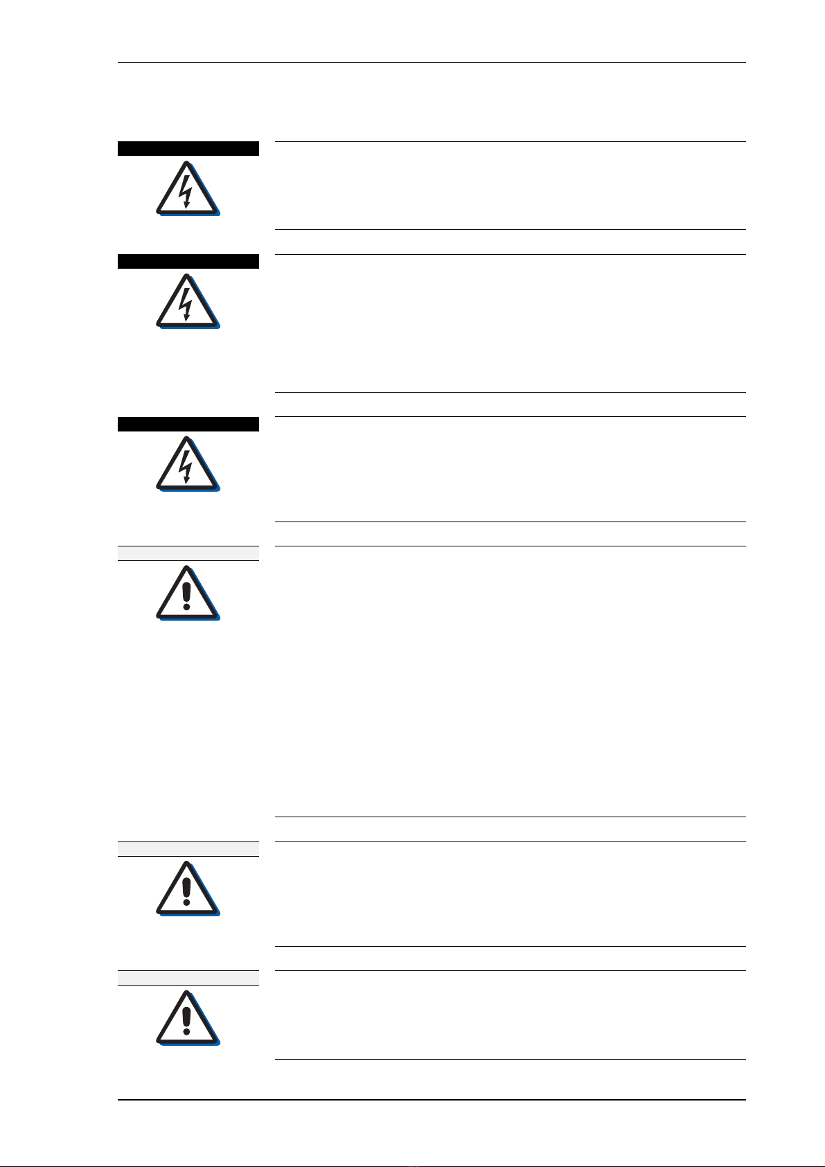
DANGER
Life danger through electrical shock
When the AC supply power is switched on, live voltages are still present
at certain terminals and tracks on the SRD 500 Doppler EU PCB.
Never touch the PCB or the connecting wires, when servicing the
SRD 500 Doppler EU under power.
DANGER
Life danger through electrical shock
Even if the power mode switch at the SRD 500 Doppler EU is in the OFF
position, live voltages are still found at certain terminals and tracks on
the SRD 500 Doppler EU PCB.
Never touch any of the electronic circuitry, particularly when setting
jumpers, plugging in and unplugging connectors or operating the power
or reset switches, When function-checking and configuring the unit
under power,
DANGER
Life danger through electrical shock
When the AC supply power is switched on, live voltages are present at
the SRD 500 system components.
Always make sure that all power supplies for the SRD 500 A system
components are switched off and safeguarded against accidental
switching-on, before wiring up the system.
WARNING
Risk of injury or death of personnel during transducer installation,
maintenance and service procedures when entering confined space
Transducers are located in confined space of vessels defined as danger-
ous working zones.
Do not enter any confined space on a ship without being trained on
safety procedures and work practices relating to confined spaces.
As a minimum, ensure that the atmosphere in the confined space is safe
and breathable. Sperry Marine recommends that a competent person
test the atmosphere for oxygen deficiency, combustible gases, hydro-
gen sulfide, and other hazardous gases that are reasonable to expect in
that area. Vent the area, as necessary, to provide a safe, breathable
atmosphere.
Never enter a confined space unaccompanied and without a third per-
son's constant supervision from a safe distance or from the entrance to
the confined space. Always make sure that all persons involved with
carry working flashlights with fresh batteries.
WARNING
Risk of flooding
If the sea chest cap is removed while the gate valve is not fully closed,
water under pressure will exit from the valve, leading to flooding of the
transducer compartment.
Always make sure that the gate valve is fully closed before removing the
sea chest cap from the gate valve when the vessel is afloat.
WARNING
Risk of flooding
If the vessel is afloat and the gate valve is opened while the sea chest
cap is not firmly attached, water under pressure will exit from between
the valve and cap, leading to flooding of the transducer compartment.
Never open the gate valve until the sea chest cap is firmly attached to it.

056361/F SRD 500 A
xiv
WARNING
Risk of electrical shock
Avoid installing the SRD 500 Doppler EU in hazardous areas.
If it is unavoidable to install the unit in a hazardous area, secure the
SRD 500 Doppler EU inside an explosion proof housing and the intercon-
necting cables inside an explosion proof conduit.
WARNING
Risk of electrical shock
Always make sure when wiring up the system that the power supply for
the SRD 500 system is switched off and is safeguarded against acciden-
tal switching-on.
CAUTION
Risk of damage
The transducer lens is a precision shape and any damage to its surface
will affect the operation characteristics of the system.
Do not scrape, chip, sandblast, grind, sand or use acid when cleaning the
transducer lens.
Do not paint the transducer assembly. If the transducer lens is acciden-
tally painted, clean the paint off the lens with paint thinner, such as tur-
pentine, then clean as regular, to ensure that no solvents remain.
Do not use acetone, gasoline or cleaners containing aromatic or chlorin-
ated hydrocarbons (benzene, toluene, carbon tetrachloride and similar
substances) to remove paint and other materials from the lens.
CAUTION
Risk of damage by unprofessional welding
Unprofessional welding bears high risks and can lead to extensive dam-
age of the vessel´s equipment.
Always maintain, that all welding work must be carried out by a qualified
welder, examined according to the rules of the relevant classification
society.
CAUTION
Risk of contamination or damage
Contamination of or damage to the surface finish of the transducer face
will alter the acoustic effectiveness of the transducer and degrade the
system performance.
Do not let the face of the transducer come into contact with grease.
CAUTION
Risk of sticking through misaligned parts
Misalignment of the sea chest parts will cause sticking of the transducer.
Possible misalignment of the gate valve relative to the spool piece cannot
be corrected once the vessel is afloat.
Make sure that all parts are aligned correctly to prevent sticking of the
transducer, when it is installed at a later point in time.
CAUTION
Risk of damage
Do not operate the SRD 500 Doppler EU while the vessel is drydocked.
Protect the transducer from damage in drydock by raising it and closing
the gate valve (see “Transducer Drydock Maintenance”).

SRD 500 A 056361/F
xv
CAUTION
Damage to the transducer function caused by cabling changes)
Cutting or shortening of the transducer cable or connecting new cables
with existing old cabling will lead to damage or malfunction.The given
length of any specific transducer cable is a necessary element of its per-
formance. Cutting or shortening as connecting to old cabling will harm
the performance characteristics of the transducer cable and lead to mal-
function of the transducer.
Always use the transducer cables in the original length. Never cut or
shorten the transducer cables. Rewire excess cable length in a loop if
necessary. Newer connect a new transducer cable to old cabling.
CAUTION
Risk of inoperable system state through power interrupt
Interrupting the power-up process after an exchange of the flashboard
may cause inoperable system state.
Make sure not to disconnect power or otherwise interrupt the power-up
process after an exchange of the flashboard.
CAUTION
Risk of inoperable device state through failure during software update
Uploading software through SUSI‘s Flash Update mode is a risky opera-
tion, as SUSI writes directly to the device’s flash memory. Furthermore,
SUSI cannot verify whether the file supplied is indeed intended for the
device under service.Under adverse circumstances, a failure during the
update may leave the device in an inoperable state.
Never interrupt an upload in progress once started.
CAUTION
Risk of damage
Components on the devices’ PCBs are sensitive to static discharge.
Electrostatic discharge may permanently damage components.
Take the necessary precautions to prevent electrostatic discharges.
Avoid touching any of the electronic circuitry.
CAUTION
Risk of damage
The NAVIKNOT electronics unit contains electrostatic sensitive compo-
nents.
Electrostatic discharge may permanently damage components.
Take the necessary precautions when servicing the electronics unit to
prevent electrostatic discharge.
Avoid touching any of the electronic circuitry.
CAUTION
Risk of damage
Incorrect assignment or mismatch of the CDU IDs will lead to incorrect
CDU settings and may corrupt the system functionality.
Always make sure that the CDU IDs are uniquely assigned when install-
ing the NAVIKNOT system.
Note
The default ID „0“ is reserved to automatically assign a single CDU as the
permanent Master CDU.
In case more than one CDU is installed, the ID „0“ is not allowed to be
assigned in any combination with other unique IDs of other CDUs.

056361/F SRD 500 A
xvi
CAUTION
Risk of inoperable device state through failure during software update
Updating software through SUSI‘s Flash Update mode is a risky opera-
tion, as SUSI writes directly to the device’s flash memory. Furthermore,
SUSI cannot verify whether the file supplied is indeed intended for the
device under service. Under adverse circumstances, a failure during the
update may leave the device in an inoperable state.
Never interrupt an update in progress once started.
CAUTION
Risk of loss of parameter settings through software update
It cannot be guaranteed that parameters settings in the User and Setup
menus and the currently active manual settings are left intact during the
software download.
Before exchanging the flashboard, or performing a software update via
SUSI, record all settings to be able to re-enter them manually, if required.
Note
For recording all parameter settings see “Setup and Configuration
Tables” in the appendix of this manual.
CAUTION
Irrevocable data loss through power interrupts
Interrupting the power-up process or disconnection from the power sup-
ply after an exchange of the flashboard will lead to irrevocable data loss
to the system.
Always maintain a regular power supply during the procedure. Never
disconnect the power supply or otherwise interrupt the power-up pro-
cess after an exchange of the flashboard.
CAUTION
Risk of inoperable device state through failure during software update
Updating software through SUSI‘s Flash Update mode is a risky opera-
tion, as SUSI writes directly to the device’s flash memory. Furthermore,
SUSI cannot verify whether the file supplied is indeed intended for the
device under service.Under adverse circumstances, a failure during the
update may leave the device in an inoperable state.
Never interrupt an update in progress once started.
CAUTION
Risk of non-compliant System State / defective Alert Handling
Software update of the NAVIKNOT electronics unit at least to version
3.000 and of all installed CDUs at least to version 2.000 is mandatory for
correct operation and alert handling of the NAVIKNOT system.
Operating the NAVIKNOT system with legacy software versions of the
NAVIKNOT electronics unit and the CDUs (software mismatch) nega-
tively impairs the alert handling and causes non-compliance of the sys-
tem.
Always make sure that the NAVIKNOT electronics unit and CDUs are cor-
rectly updated before operating the NAVIKNOT system.
Note
In case of Software Mismatch, the NAVIKNOT system is in non-compliant
system state and the alert handling is not operable.
The NAVIKNOT EU and all installed CDUs must correctly be updated
before operating the NAVIKNOT system again.
Proceeding with operating the NAVIKNOT system in a non-compliant
system state is not allowed.
SRD 500 A 056361/F
xvii
CAUTION
Risk of inoperable device state through cable problems
Trying to execute the CDU software update wrong or damaged RS-232
connection cable will leave the CDU in an inoperable state.
The CDU software update can only be carried out with a special RS-232
connection cable, to connect to the receptacle on the CDU PCB.
Always check that the correct Sperry Marine cable is available and that
the cable is undamaged before executing the CDU software update.
Never execute the software update with wrong or damaged connection
cable. Never interrupt an update in progress once started.
Note
For software update of the NAVIKNOT system components, the correct
sequence of update procedures is mandatory:
- In case the installed CDUs DO NOT have the MOST CURRENT SW ver-
sion, the Software of the CDUs must ALWAYS be updated before the EU
software.
- In case the installed CDUs already DO have the MOST CURRENT SW
version, only the Software of the EU must be updated.
Note
The information and menu descriptions in this Operation, Installation
and Service Manual are applicable from software versions:
NAVIKNOT EU, Rev. D, 3.000
NAVIKNOT CDU, Rev. K, 2.000
Note
In the maintenance mode, the SRD 500 Doppler EU will no longer trans-
mit valid speed or depth data.
The SRD 500A CDU, will display dashes instead of speed and depth data.
External equipment may raise alerts due to loss of data. This condition
will persist until the maintenance mode is quit and the SRD 500 Doppler
EU resumes normal operation mode again.
Note
NAVIKNOT complies with the statutory requirements regarding a serial
interface for the alert management (alert presentation and acknowledge-
ment) by a Central Alert Management System (CAM) following IEC 61162
(NMEA 0183) and MSC.302(87) (BAMS).
Note
The differentiation of the alert handling is by selecting either
ALR (for AMS/CAMS) or ALF/ALC/ARC (for BAMS) as NMEA message in
the Service Setup 600.
Note
The selection of the alert management system must be chosen according
to ship classification requirements and hardware equipment during
installation and must not be changed when the ship is in operation.
Note
Correct alignment of the transducer is critical for the accuracy of the sys-
tem and must be carried out as precisely as possible.
Note
Further safety information for service personnel is presented in the
respective chapters of this manual.

056361/F SRD 500 A
xviii

SRD 500 A 056361/F
System Information 1-1
Chapter 1: Introduction
1.1 System Information
Intended Use
The SRD 500 A is a dual-axis Doppler speed log system for the maritime
navigation of vessels and must only be operated from appropriately
trained and educated personnel familiar with all mandatory safety and
operating procedures.
The SRD 500 A system provides ground and water referenced longitudi-
nal and transverse speed and distance information for the navigation of
maritime vessels.
Water depth information as well indicated by the SRD 500 A system is
for reference only. The indication of water depth information is can-
celled, when the system is operated in the “BSH” mode of operation.
Not Intended Use
The SRD 500 A dual-axis Doppler speed log system is not allowed to be
used for the navigation of inland water vessels and river boats.
The SRD 500 A dual-axis Doppler speed log system is not type approved
as an echo sounder. Water depth indications given by the SRD 500 A
system are therefore not applicable as the only data source for naviga-
tion purposes when accurate water depth data are needed.

056361/F SRD 500 A
1-2 System Overview Transducer and Sea Chest
1.2 System Overview Transducer and Sea Chest
Figure 1-1:
Parts Reference
Sea Chest and
Transducer
2
3
4
5
6
7
1
18
17
5
9
10
11
12
16
15
14
13
8
Table of contents
Popular Transducer manuals by other brands

S+S Regeltechnik
S+S Regeltechnik PREMASGARD 1140 Operating Instructions, Mounting & Installation

Rotronic
Rotronic CF1 Series Short instruction manual

Signaltec
Signaltec MCTS II installation manual

Lumel
Lumel P18 user manual

HBM
HBM C18 Mounting instructions

Siemens
Siemens XLT Series operating instructions


