Spicer Consulting SC22 User manual

1 19-Oct-2007
SC22 Magnetic Field Cancelling System
SYSTEM SC22
•
Protects your investment in electron
beam technology by stabilising the
magnetic field environment
•
Cancels and monitors the AC field
•
Low cost, high performance system
•
Intelligent user interface
•
Automated set up
•
Cancels AC fields from 0.5 Hz to 5 kHz
50 x field improvement at 60Hz
•
Full 3 axis (X, Y, Z) system
•
Up to 60 mG (6.0 µT) pk-pk range
•
Adapts to field changes within 100 µs
•
Supports dual sensors for TEMs and
high gradient fields
•
USB monitoring port
Overview
Today’s high performance electron beam tools
are very sensitive to changing ambient magnetic
fields. The fields move the beam causing loss of
resolution and measurement accuracy. The
SC22 system reduces the ambient AC field and
restores the resolution and accuracy.
The SC22 system comprises a Magnetic Field
Control Unit, an AC Magnetic Field Sensor and
three multicore cables, which are installed in the
room where the field is to be cancelled.
Each power amplifier in the control unit drives a
current through its cable to create a field of the
opposite sign to the change in ambient field.
The magnetic field sensor measures the
resulting field and real time negative feedback
reduces the ambient field by the loop gain of the
system.
The system is dynamic, automatically
responding to field changes within 100 µs. AC
Line fields (50/60 Hz) are reduced by 50 x.
The SC22 does not cancel DC field changes
from sources such as elevators, trains and
traffic. The larger SC20 system is available to
cancel both AC and DC fields.
SPICER CONSULTING
SPICER CONSULTING, Eden Laboratory, Broadmead Road, Stewartby, Bedfordshire, England MK43 9ND
Tel: +44 1234 765773 Fax: +44 1234 765778 E-mail: enq@spicerconsulting.com Web: www.spicerconsulting.com

2 19-Oct-2007
Product Description
The SC22 is a fourth generation Magnetic Field
Cancelling System, designed to improve the
performance of electronic instruments that are
sensitive to magnetic fields, such as electron
microscopes and electron beam metrology tools.
The SC22 is a replacement for the SC12 system,
which has an installed base of over 1000 units
world wide.
It is important to note that mechanical vibration,
acoustic noise and ground loops in the electron
beam tool installation can produce imaging
defects similar to magnetic fields. The SC22
cannot improve images which are affected by
these other interfering sources because they are
not magnetic fields.
A typical SC22 system installation on an SEM is
shown in Fig. 1. The control unit is not shown.
The cables make one turn and are shown in red,
green and blue. The actual cables are grey and
usually installed in white plastic conduits. Where
the room has a false ceiling, the Z cable is usually
installed above it. The magnetic field sensor is
located close to the bottom of the electron beam
column. An optional mount enables it to be
strapped to the column if required.
The amount by which the field is reduced is
determined by the loop gain of the system, which
is automatically set by the SC22 to 50 times. The
system does not cancel the earth’s DC magnetic
field, nor does it cancel the field everywhere in
Fig. 1 Typical SEM Room Installation
the room. It creates a region around the magnetic
field sensor where the AC field is much reduced.
The volume of this region depends mostly on the
gradient of the ambient field and the positioning
of the field cables.
The SC22 control unit displays the amplitudes of
the X, Y & Z field components and the total
vector field on its LCD panel. Tesla and Gauss
units, RMS & pk-pk can be selected. The
measuring system can resolve 1µG (100 pT) field
changes. The real-time measured fields are
available on front panel BNC’s as analog voltage
levels for oscilloscope display.
The magnetic field amplitude is continuously
monitored and compared with preset “trip levels”
to provide “GO/NOGO” indication of the field
quality. The LCD panel and a small green LED
on the sensor indicate that the field is “OK”.
The SC22 controls are much simpler than the
SC12 and are supervised by the embedded
microcomputer. There are just 3 control buttons
on the front panel. The “units” button enables
choice of the displayed field units. It has no effect
on field cancelling. The “setup” button starts a 4
second program that measures and sets the gain
and phase of the feedback loop. The “cancel/
standby” button turns cancelling on and off.

3 19-Oct-2007
The SC20 Control Unit
Installation options
The SC22 field cancelling cables are made with a
loop and a tail. The loop creates the field and the
tail (which makes no field) connects the loop to
the control unit. The loop parts are shown in Fig.
1 in red, green and blue. SC22 room cables have
X and Y loops 16 metres long and a Z loop 20
metres long. Longer cables are available to
special order.
The Fig. 1 installation is suitable for most SEM
applications where the electron beam column is
typically 1.5 metres from the room walls. The
maximum field which can be cancelled (the
dynamic range) depends on the size and position
of the cable loops relative to the electron beam
column. With 5m x 3m X and Y loops and the
column 1.5m from the walls the dynamic range is
about 25 mG (2.5 µT) pk-pk.
To specify the SC22 performance more
rigorously, we use a reference room cable
installation. This is shown in Fig. 2. The electron
beam column is centred in the 3m x 5m X and Y
loops (which cross over above and below the
column) and the 5m x 5m Z loop. The SC22
specifications on page 6 apply to this reference
room installation.
For leading edge TEM installations, double loop
room sized helmholtz cables are available. These
are recommended for TEM’s fitted with Gatan
Imaging filters (GIF’s). Customers are advised to
consult Spicer Consulting support staff for
design and installation of these special field
cables.
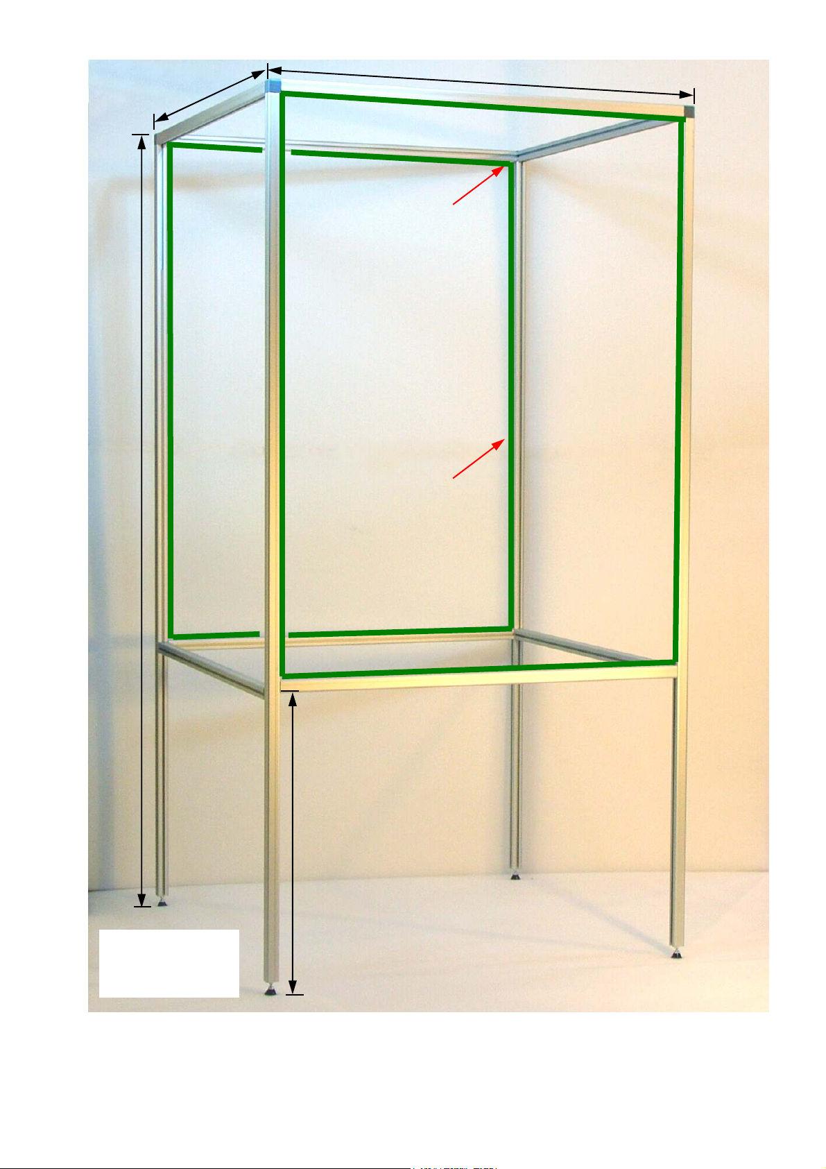
When the room is large or in clean rooms where
there are no local walls, a frame around the
electron beam tool can be used to mount
Helmholtz cables. Fig. 3 shows our current frame
design. A frame limits access to the tool so
should only be used where room cable
installation is not possible. The cancelling
performance with a frame may be inferior to a
room cable installation.
Z FIELD CABLE LOOP
Y FIELD CABLE LOOP
X FIELD CABLE LOOP
CABLE
TAIL(Z)
MAGNETIC FIELD
CONTROL UNIT
E-BEAM
COLUMN
5 METRES
MAGNETIC
FIELD
SENSOR
3 METRES
5 METRES
NOTE: THIS IS A PERSPECTIVE DRAWING.
THE CABLE LOOPS ARE RECTANGULAR AND ORTHOGONAL
Fig. 2. Reference room installation
4 19-Oct-2007
W
INSULATED JOINTS,
ALL 8 PLACES
H
D
A
(ADJUSTABLE
ON SITE)
Y FIELD CABLE
(2 LOOPS) ON
FRAME
Frame is made to order. Customer specifies dimensions H, W, D.
Frame in photo has H=2060, W=1060, D=1060 mm.
Frame is supplied dismantled, for on-site assembly.
Fig. 3 Frame for
Helmholtz Coils

5 19-Oct-2007
Sensor options
The SC22 AC field sensor is shown in Fig. 4 and
on the optional sensor mount in Fig. 5. The sensor
mount is for attaching the sensor to an electron
beam column. Fig. 6 shows a typical installation
on an SEM where the sensor is standing on the
work chamber at the bottom of the column. This
is the most common configuration with one
sensor.
For some applications, there are advantages in
using two sensors. An example is shown in Fig. 7.
When two sensors are used their outputs are
combined by a mixer shown in Fig. 8.
The mixer creates a “virtual sensor” which can
appear to be located inside the column. The mixer
controls enable the apparent position of the sensor
to be adjusted separately for the X, Y, and Z axes
to tune the cancelling system for optimum
improvement in the tool imaging.
AC SENSOR 1 AC SENSOR 2
Fig. 7 Sensors on JEOL TEM
Fig. 4 SC22 AC Sensor
Fig. 6 Sensor on JEOL SEM
Fig. 5 SC22 Sensor mount
Fig. 8 SC22 Mixer

6 19-Oct-2007
Specifications
CO-ORDINATE SYSTEM X, Y, Z rectangular Cartesian
UNITS Gauss, Tesla (switchable)
FIELD CANCELLING
Components cancelled X, Y, Z field components
Dynamic range (X & Y)
(note:1)
60 mG (6 µT) pk-pk (installation Fig. 2)
Dynamic range (Z)
(note:1)
45 mG (4.5µT) pk-pk (installation Fig. 2)
Field cancelling factor 50 X at 50/60 Hz
Bandwidth 0.5 Hz - 5000 Hz
System 1/f noise limit below 0.1Hz < 100 µG (10 nT) pk-pk
System wideband noise limit 1 µG (100pT) RMS 5 Hz - 20 kHz
FIELD MEASUREMENT and MONITORING
Display 3.5 inch LCD TFT colour panel
Measurements displayed X axis field at sensor
(updated every 0.4 secs) Y axis field at sensor
Z axis field at sensor
TOTAL vector field at sensor
Measurement bandwidth 5 Hz -20 kHz
Readout units selectable mG RMS
mG pk-pk
µT RMS
µT pk-pk
nT RMS
nT pk-pk
Display range (reading) X, Y, Z pk-pk 0 - 40.000 mG (0 - 4.0000 µT) (0 - 4000.0 nT)
X, Y, Z RMS 0 - 20.000 mG (0 - 2.0000 µT) (0 - 2000.0 nT)
TOTAL pk-pk 0 - 69.282 mG (0 - 6.9282 µT) ( 0 - 6928.2 nT)
TOTAL RMS 0 - 34.641 mG (0 - 3.4641 µT) ( 0 - 3464.1 nT)
(note: sensor output clip detector displays if pk-pk exceeds 99% of range)
Accuracy
± 1.0 % of reading ± 1µG (100 pT)
Sensor wideband noise limit 1 µG (100pT) RMS
Field OK indicator Green field OK indicator appears when X & Y & Z fields are < 250 µG RMS
Trip indicators X, Y, Z Trip indicator appears if the field on that axis > 250 µG RMS
and disappears after 60 seconds if the field < 250 µG RMS
X, Y, Z REAL TIME FIELD OUTPUTS
Scaling 1.0 V/mG (10V/µT)
Range ± 12 Volts
Source resistance 10 kΩ
Connectors 3 x BNC
Bandwidth 5 Hz - 20 kHz
POWER 120/240 V (+10% -20%) 50/60 Hz , 50 VA
Note 1: Dynamic range is stated when operating at the nominal AC power input of 120 or 240 volts RMS.
de-rate linearly for lower voltages.
SPICER CONSULTING, Eden Laboratory, Broadmead Road, Stewartby, Bedfordshire, England MK43 9ND
Tel: +44 1234 765773 Fax: +44 1234 765778 E-mail: enq@spicerconsulting.com Web: www.spicerconsulting.com
Other Spicer Consulting Laboratory Equipment manuals

Popular Laboratory Equipment manuals by other brands


Thermo Scientific
Thermo Scientific SHKE8000 Series Operating and maintenance manual

Thermo Scientific
Thermo Scientific Sorvall T3 user manual

Restek
Restek SilcoCan quick start guide

Tektronix
Tektronix TSG130A instruction manual

Resodyn
Resodyn LabRAM II Installation and user manual

vacuubrand
vacuubrand VHC pro Instructions for use


