Zubler VARIOmaster FZ1 User manual

Seite
www.zubler.de
FZ1
VARIOmaster®
Suction nit
en
Operation Instructions 08-2006

3Page
Signs and Symbols
Risks and dangers
This symbol marks
safety instructions that
must be followed to
prevent injury or
death.
Risk of electric shock
Contents
0. Introduction Page 4
0.1 Declaration of conformity
0.2 eneral information
0.3 Proper use
0.4 Functions
0.5 Technical requirements
0.6 Scope of delivery
1. Installation Page 8
1.1 FZ1 VARIOmaster
vacuum system
1.1.1 Setting up the unit
1.1.2 Connecting the unit
1.2 Vacuum position opener
1.2.1 AP501 automated
opening module
1.2.2 R1400 intake system
1.2.3 Dust socket
2. Operation Page 14
2.1 LED indicators
2.2 Control panel
2.3 Setup
2.4 Settings
3. Maintenance and service Page 19
3.1 Emptying the dirt container
3.2 Replacing the dust filter
3.3 Replacing the fine filter
4. Intake system Page 22
4.1 Requirements
4.2 Zubler parts and accessories
5. Specifications Page 24
5.1 Technical specifications

4
0.
Page
Einleitung
We, Zubler erätebau mbH
Buchbrunnenweg 26
89081 Ulm-Jungingen,
ermany
hereby declare, that the suction unit
FZ1 VARIOmaster®
is in compliance with the protective
requirements in accordance with the pro-
visions of the following directives:
98/37/E Machines Directive
73/23/EW Low-Voltage Directive
89/336/EW EMV Directive
In the event of any amendments being
made to the product without our agree-
ment, then this statement shall no longer
be valid.
Ulm, den 15. July 2005
Kurt Zubler
Managing Director
0.1 Conformity Declaration

5Page
This vacuum system is intended exclusively for dry dust!
Removing other types of dust or gases must be approved by the manu-
facturer prior to setting up the unit.
If visible dust clouds occur or if the vacuum performance is clearly not
sufficient, discontinue your work and turn off the unit, then contact
your dealer or our customer service team.
The volume of air circulated by all vacuum systems taken together and
returned to the room must not exceed 50% of the indoor air volume
per hour for all enclosed spaces. An air change factor of ? 1/hour is
required. Removal of the exhaust air generated by the vacuum system
to outside the building is preferable to recirculation.
This system may only be operated by persons who have been instruc-
ted in its use and specifically tasked with its operation. We reserve the
right to make changes to the system without such changes necessarily
being reflected by these Instructions of Use.
0.3 Proper use
0.2 General information
Dear customer:
Thank you for purchasing a Zubler 2-position vacuum system. We hope
this system will give you a pleasant workplace experience. Our technolo-
gy undergoes continuous improvement and development based on our
cooperation with experienced dental technicians. Our objective is to make
vacuum technology quieter and ever more agreeable to work with.
Performance and economy are of course basic requirements.
In order to ensure seamless operation, we recommend reading these
Instructions for Use carefully.
We would also like to point out that complex technical devices require
service and repair tasks to be performed by specially trained personell.
Zubler ensures that all repairs are properly executed using a regional tech-
nical center. Each repair performed by Zubler is guaranteed for six
months.

6Page
0.4 Functions
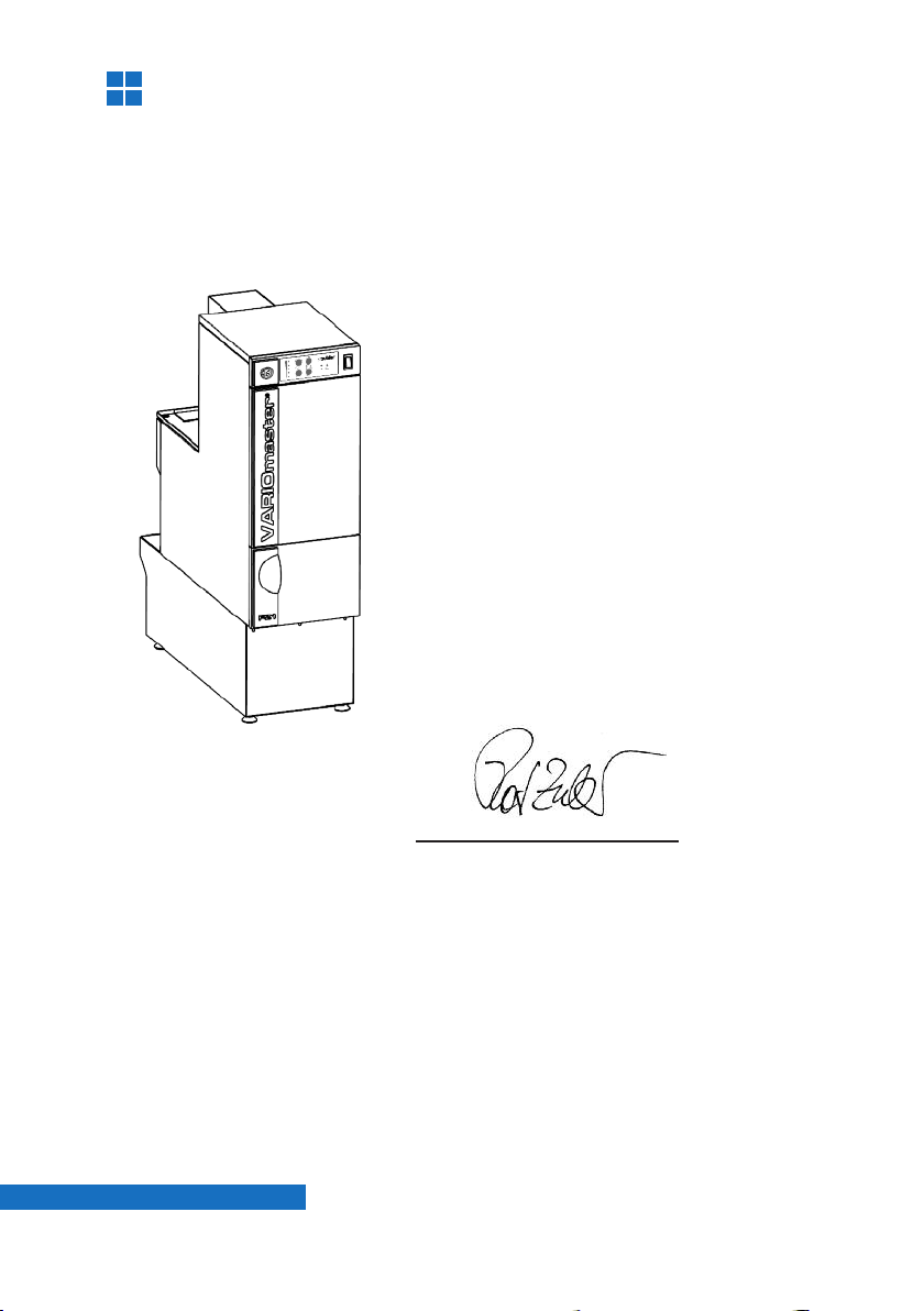
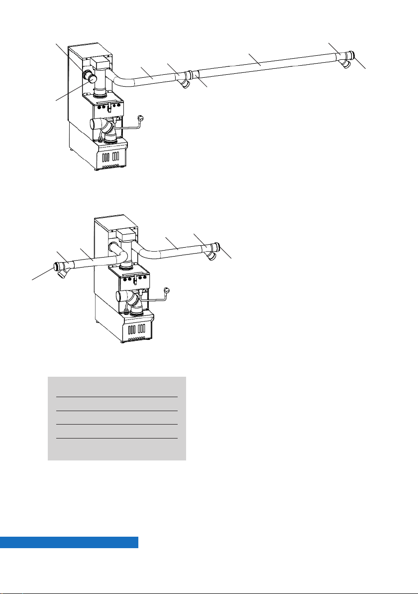
The FZ1 Variomaster vacuum system is a centralized vacuum system for
the operation of up to 2 vacuum positions simultaneously. It may be
expanded to include up to 4 vacuums positions, operated alternatingly.
This vacuum system consists of a central suction unit with integrated fil-
ter technology and independent vacuum position openers at the individual
working positions.
It is possible to connect all devices that generate dry dust in the dental
laboratory.
The vacuum system allows the assignment of four suction levels (1–4)
that can be programmed individually for each vacuum position, depending
on the amount of dust generated. This function is active only for as long
as only a single vacuum position is open.
Level 1234Maximum
Suction power (approx.) 16 l/s 20 l/s 25 l/s 35 l/s 45 l/s
If 2 vacuum positions are open simultaneously, both will have the same
suction power independent of any program settings; this suction power
will correspond to suction level 3 (factory setting). The suction level for
concurrent use can also be programmed.
Polishing units with 2 intakes or units that require excessive air volumes
must be connected via dual valves (see special applications).
The FZ1 Variomatic vacuum system keeps the preprogrammed suction
level constant at each vacuum position, automatically compensating for
filter clogging.
The filter will be automatically cleaned as soon as the vacuum turbine has
reached its maximum performance level. In addition, the filter will be
cleaned at preselected intervals in order to keep energy consumption low.
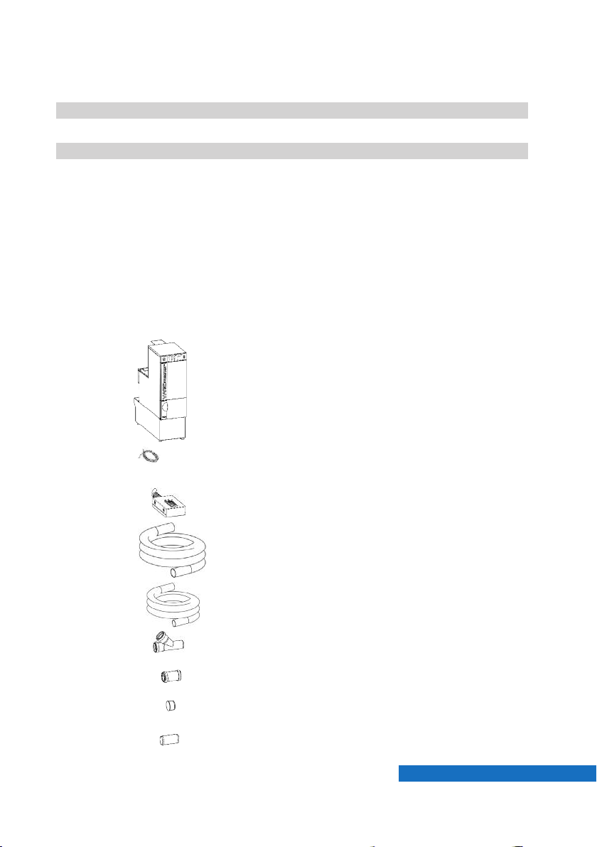
The AP501 automated vacuum position opener automatically opens the
vacuum positions as soon as the dust-generating unit connected to it is
turned on.
The R1400 intake system allows all vacuum positions to be opened
manually.
All opening modules require a control line connecting it to the suction unit
for turning the unit on or off.

7Page
1x FZ1 VARIOmaster®vacuum system
1x Power cord
1x Programming module
5m 50-mm hose
2m 40-mm hose
2x 50/40 x 45° Y branch
1x 50-mm double sleeve
2x 50-mm dummy covers
1x 50-mm pipe joint
0.6 Scope of delivery
The vacuum system is delivered complete with installation components
allowing two vacuum positions to be created on one side of the vacuum
system at a distance of approximately 6 m.
Make sure to check the installation components provided for complete-
ness. Some of the components will be found in the dirt container of the
vacuum system.
0.5 Technical requirements
Temperature +5°C to +40°C (+41°F to +104°F)
Relative humidity max. 80% (at 30°C)
Power rating 230V/110V – 1200 W
Exhaust connector Ø 75 mm (optional)

8
1.
3
8
9
2
10
45
6
7
1
11
1 Cover
2 Filter suspension
3 Connecting pipe
4 Filter cover
5 Shake/deflate filter
6 Safety filter
7 Main unit housing
8 Power cord
9 Foundation housing
10 Transport lock
11 Dirt container
Page
Fig. 1: FZ1 VARIOmaster
1.1.1 Setting up the unit
■Stand the vacuum system vertically
on a level surface.
■Make sure that the walls of the vacu-
um system housing do not touch any
furniture in order to prevent vibrations
from being transmitted.
■Make sure that the vacuum system is
accessible from above or can be pul-
led out in a forward direction. This is
necessary when replacing the filter.
■Make sure all connections are accessi-
ble from behind.
■Remove the installation components
from the dirt container (11).
■Remove the styrofoam transport lock
below the filter (10)
1.1 FZ1 VARIOmaster vacuum system

9
12
13
15 14
16
Page
Fig. 2: FZ1 VARIOmaster
rear view
12 50-mm intake nozzle
13 Control cable connector
14 DN75 exhaust pipe
15 Motor cord
16 Motor cooling exhaust
1.1.2 Connecting the unit
■You can choose to have the exhaust
air of the vacuum system blowing up
to the left, to the right or to the back
by rotating the exhaust pipe (14).
■We recommend allowing the exhaust
air to be removed from the building.
To do so, install a DN75 pipe that
ends outside the building. The length
of the pipe should not exceed 10 m.
Do not use any 90° angles!
■The exhaust air, once the dust has
been removed, may also be returned
to the room
(see chapter 0.3, page 5)
■Connect the vacuum positions and the
intake nozzles (12) with the 50-mm
suction hose (see Figs. 3 and 4, page
10).
■Use the control cable to connect one
of the connectors (13) on the suction
unit to the appropriate socket on the
vacuum position opener.
■Connect the power cable (8) to the
vacuum system and to the wall socket.
■Make sure that the exhaust and intake
air promoter cooling at the back of the
unit (16) can circulate freely.

10
18
18
17
17
17
20
18
18
21
21
21
21
17
19
Page
Fig. 3:
Fig.4:
17 Branch
18 Dummy cover
19 Sleeve
20 50-mm pipe joint
21 50-mm suction hose or pipe
Vacuum position installation on one
side only
■If all vacuum positions are located on
the same side of the vacuum system,
one of the intake nozzles is closed off
with a sleeve (19) and a dummy cover
(18).
■The maximum distance that is possi-
ble with the installation material enclo-
sed is approximately 6m (19 feet).
Vacuum position installation on both
sides
■If vacuum positions are located on
both sides of the vacuum system,
both intake nozzles are used.
■Branches (17) where a suction line
ends are closed with a dummy cover
(18).
■Use the 50mm pipe joint (20) to con-
nect the line to the next vacuum posi-
tion.
■Branches (17) should always be loca-
ted approximately 30–50cm away
from the following vacuum position.
■Alternatively, the entire installation can
be executed in standard 50mm flexi-
ble pipe.

22
25
23
24
11
23
48 49
50
49
50
next vacuum
position
Page
Fig.5: autom. Opener AP501
1.2.1 AP501 automated opening module
■The AP501 automated vacuum positi-
on opener (23) automatically opens
the vacuum position and starts the
vacuum system once the handpiece
or other connected device is actuated.
■The vacuum position valves (24) are
inserted directly into the branches
(17).
■Each working position must be con-
nected to the vacuum system via a
vacuum position opener. The vacuum
position openers actuate the vacuum
system via their control cables (22).
22 Control cable
23 AP501 vacuum position opener
24 Vacuum position valve
25 40-mm hose
48 FZ1 connector
49 Switch
50 Programming module
■The vacuum position valve and the
intake system are connected with a
40mm hose (25) whose maximum
length must not exceed 1.5m (5 feet).
1.2 AP501 automated opening module

22
25
24
27
12
26
next vacuum position
1.2.2 R1400 intake system
■The R1400 intake is a combination of
a mechanical vacuum position opener
and a suction funnel. The vacuum
position is opened and the vacuum
system started by pulling out the suc-
tion hood.
■When installing mechanical openers, a
40-mm pipe joint is used instead of a
vacuum position valve (27).
Note: The R1400 intake system is a
manual opener. Its use in connection
with vacuum systems tested by TÜV
for BIA has not been approved by the
relevant erman employers’ mutual
insurance association, B FE.
26 R1400 intake system
27 40-mm pipe joint
Fig.6:
Page

13
2.
®
-
+↵
29 30 31
36 35 34 32
28
33
Operation
Page
2.2 Display
Fig. 7:
28 Input module connector
29 Suction power indicator LEDs
30 Plus key (+)
31 Enter key with LED
32 Container indicator LED
2.1 LED indicators
■The suction power indicator LED (29) indicates the suction level of the
active vacuum position.
■A blinking red Container indicator LED (32) indicates that the program-
mable timer for checking the container has run down. It is possible to
continue working until the next start of the vacuum system. The timer
is reset by lowering the dirt container.
■A steadily lit red Container indicator LED (32) indicates that the dirt
container has been lowered.
■A blinking red Service indicator LED (34) indicates that the necessary
minimum air volume cannot be achieved despite cleaning. The vacu-
um motor will be deactivated, and the vacuum system will not be ope-
rative. Possible causes are a clogged main or fine filter or clogged
motor air outlets.
■A steadily lit red Service indicator LED (34) indicates an electrical pro-
blem.
33 Main switch with LED
34 Service indicator LED
35 Auto/Duration key with LED
36 Minus key (–)
Page

14Page
2.4 Settings
■The input module can be used to
modify the basic parameters of the
FZ1 VARIOmaster vacuum system;
the same one is also used for adju-
sting the sensitivity of the AP501
automated vacuum position opener.
■Connect the plug of the input module
to the appropriate socket (28) on the
vacuum system.
2.3 Setup
■Turn on the unit by switching the main switch (33) to the ON position.
The green switch indicator LED will be lit.
■The vacuum system turns on the vacuum motor to maximum power
and then successively opens the valves of the connected AP501 auto-
mated vacuum position opener in order to automatically clean the sucti-
on hoses.
■This is followed by a cleaning cycle with three successive cleaning
impulses.
■The vacuum system is now ready for use. The AP501 automated vacu-
um position openers will be activated, and the devices connected can
now be used.
■All that remains to be done is to adjust the sensitivity of the AP501
automated vacuum position openers to the specific devices you are
using. For details, please consult the AP501 Instructions for Use manual.
■When operating a single device, the suction power can be adjusted indi-
vidually to the necessary suction level by pressing the Plus (30) and
Minus (36) keys. Confirm the setting by pressing the Enter key (31).
Note: Automatic cleaning of the pipes will only be performed if an AP501
vacuum position opener is connected. If only manual openers are con-
nected, the vacuum system will immediately proceed to the filter-
cleaning step.

15
88
91
90
89
0000 c
----
C 1 ●
1 6 ●
Page
2.4.1. Filter cleaning interval
The vacuum system automatically per-
forms filter cleaning at regular intervals in
addition to any necessary cleaning in the
event of a seriously clogged filter. The
objective is to save energy by making
sure that the vacuum motor is not perma-
nently operating near the level of maxi-
mum filter clogging.
The cleaning interval has been factory-
preset to 2 hours. You may adjust this
value as needed based on the amount of
dust generated at your vacuum positions.
A value of 1 corresponds to an interval of
15 minutes.
A value of 8 corresponds to an interval of
8 x 15min, which is, 2 hours.
Example: You would like the filter
cleaning to be performed only every four
hours:
Fig. 8: Eingabemodul
88 LCD display
89 Code entry key
90 Enter key
91 Numeric keypad
Enter a value of 16 and confirm
by pressing the Enter key.
Display
Display

16
0000 c
----
C 2 ●
51 0 ●
2.4.2. Dirt container checking interval
The filling status check for the dirt contai-
ner is implemented in the form of a time-
controlled power-down of the vacuum
system. The actual filling level of the dirt
container is not checked. You may adjust
the dirt container checking interval after
observing the amount of dust generated
at your vacuum positions during the first
few weeks of operation.
The factory interval 80 hours of operation
(including standby times). This means
that you would be prompted to check the
dirt container every 1–2 weeks. For
instructions on how to empty the dirt
container, please consult chapter 3.1 on
page 19.
A value of 1 corresponds to an interval of
1 hour.
A value of 80 corresponds to an interval
of 80 hours (max. 250).
Example: You would like the unit to be
powered down for checking the dirt con-
tainer only every 150 hours:
Enter a value of 150 and con-
firm by pressing the Enter key.
Display
Display
Page

17
0000 c
----
1●
3C 1 ●
2.4.3. Vacuuming Socket
With the vacuuming socket ST03 and a
cleaning set it is possible to clean the
workspace and vacuum the floor.
■By opening the front cover of the
vacuum socket, the suction is started.
■Therefore the wire (22) must be con-
nected to one of the 4 data connec-
tors (13) on the suction unit.
■Various cleaning sets and accessories
are available within the delivery pro-
gram.
Setup:
For vacuuming it is necessary to dis-
able the regulation, otherwise the unit
will always display "filter clogged".
Therefore the suction unit must be
programmed with the information to
which data connector (13) a vacuu-
ming plug is connected.
E.g.: There is a vacuuming plug connec-
ted to data connector No.1.
For data connector No. 2-4 enter C32-
C34 instead and change the value to 1.
The regulation is activated again by set-
ting the value of C31-C34 back to 0
Enter a value of 1 and confirm
by pressing the Enter key.
Display
Page

18
3.
38
37
Maintenance and service
3.1 Emptying the dirt container
Once the timer for checking the dirt con-
tainer has run down, the Container indica-
tor LED (32) will be lit intermittently.
You may continue to work in this situati-
on. If the vacuum system is powered on
again, e.g. on the next working day, it will
not be ready until the container has been
checked.
Proceed as follows:
■Leave the vacuum system turned on.
■Open the container door (37) and
press the bracket (38) downward. The
Container indicator LED (32) will now
be lit permanently.
■Pull out the container and empty it of
all dust.
■Reinsert the container as far as it will
go and push the bracket (38) upward.
The Container indicator LED (32) will
be turned off, and the vacuum system
will once again be operative. The
timer for checking the dirt container is
reset.
■Based on the amount of dust found in
the dirt container, you may adjust the
dirt container checking interval as
appropriate, as described in chapter
2.4 on page 17.
37 Container door
38 Bracket
Fig. 9: container change
Page

19
31
51
39
42
5
5
43
41
1
Fig. 11
Fig. 10
■Turn off the unit by switching the
main switch (33) to the OFF position.
■Pull out the vacuum system from
underneath the workbench if necessa-
ry. You need free access to the top of
the vacuum system.
■Remove the two screws (51) on the
back of the unit. Remove the top
cover (1). (I)
■Disconnect the cleaning cable (39)
from the cleaning unit (40), and open
the 4 twists screws (41) by turning
them by 90° using a coin. (II)
■Remove the cleaning unit including
the filter cartridge (5) by lifting it
upward and out.
■Opened the knurled knob (42) and
remove the filter cartridge complete
with its centring disc (43). (III)
■Reinstall new filter in reverse order.
3.2 Replacing the dust filter
1 Upper cover
39 Cleaning cable
40 Cleaning unit
41 Twist screw
5 Filter cartridge
42 Knurled knob
43 Centring disc
51 Screws
Wear suitable protective gear (pro-
tective gloves, respiratory protection)
whenever replacing a main or fine fil-
ter
Page

20
42
43
■Pull the centering disk (43) off the
thread rod. It may be necessary to
loosen the sealing with a screw driver.
■Remove the filter cartridge by pushing
the threaded rod. (Fig. 12)
Before mounting the new filter cartrid-
ge remove dust from the sealing.
Slide the cerntering disk (43) over the
thread rod and ensure the new cartrid-
ge is centered on the sealing.
■Screw the clamping lever (42) onto
the thread rod until touching the disk.
Clamp the lever once but loosen it
again.
Now you can turn the lever again wit-
hout pressure until the resistance
starts. (Fig. 14a)
From this point turn the lever at max.
90° to the next slot of the centering
disk. (Fig. 14b)
■Clamp the Lever (42) that the latch
matches with a slot of the centering
disk (43).
Place the cleaning unit back into the
suction unit, tighten the 4 twist
screws (41) and plug in the cleaning
cable (39).
Fig. 12
Fig. 13
Fig. 14
Page

21
44
6
46
45
47
Fig. 15
Fig. 16
Store contaminated filters in a tightly
sealed container or plastic bag imme-
diately after removal and dispose of
according to all applicable waste dis-
posal regulations.
3.3 Replacing the fine filter
44 Pipe segment
45 Quick-release lock
46 Fine filter cover
47 Vacuum hose
■Turn off the unit by switching the
mains switch (33) to the OFF position.
■Pull out the vacuum system from
underneath the workbench if necessa-
ry. You need free access to the back
of the vacuum system.
■Push the pipe section (44) all the way
to the top and open the quick-release
lock (45). (I)
■Remove the fine filter cover (46).
Remove the pipe section from the
upper seal. (II)
■Disconnect the vacuum hose (47)
from the fine filter cartridge (6) and
remove it by pulling it upward and out.
(III)
■Reinstall new filter in reverse order.
Page
Table of contents
Other Zubler Laboratory Equipment manuals