SPIETH 365A User guide

ASSEMBLY AND CARE INSTRUCTIONS
JUST FOR KIDS CANTILEVER BARS
365A
VERSION: 8920101 (Revised 10/17)
SALES AND SERVICE
spiethamerica.com
Canada and International
135 Forestview Road, Oro-Medonte
Ontario, Canada L3V 0R4
Toll-Free: (800) 563-6479
Telephone: (705) 325-2274
Fax: (705) 325-1485
USA
3327 Ranger Road
Lansing, MI 48906
Toll-Free: (800) 331-8068
Telephone: (517) 999-8230
Fax: (517) 999-8245
service.usa@spiethamerica.com
365A JFK CANTILEVER BARS Assembly Instructions
Page 2 of 13
Thank you for purchasing a SPIETH America Cantilever Bars from our Just For Kids line of
Gymnastics equipment. We appreciate your business and value you as a customer.
The Just For Kids Cantilever Bars come complete with cable tie-down and Threaded Socket
Adapters (Hardwood floor sockets are also available but must be purchased separately).
This equipment is manufactured of the finest materials and has been thoroughly inspected before
leaving our plant. We are sure you will be pleased with its quality, durability and performance. Please
carefully read the following instructions before assembling and using your new equipment, as they
pertain to the particular equipment you have purchased.
The exclamation mark symbol when seen in this manual is used to indicate warnings or
items that require special attention during the use or assembly of the apparatus.
Assembly, set-up and adjustment of this equipment should only be undertaken by
qualified persons. At no time should children or other unqualified persons undertake
the assembly, set-up, installation or adjustment of this equipment.
THE SPIETH AMERICA JUST FOR KIDS CANTILEVER BARS ARE DESIGNED AND
INTENDED FOR USE BY BEGINNER LEVEL GYMNASTS UNDER A WEIGHT OF 150
LBS (68 KG).
For assembly and set-up instructions, please read and follow all instructions in Section I of this
booklet as they apply to your particular piece or pieces of equipment.
Tools Required:
7/32” & 3/16” Allen keys (Supplied)
2 Adjustable Wrenches
3/4” or 19mm Socket, Extension and Ratchet
Tape measure
5/8” diameter carbide concrete drill bit
Hammer Drill, Shop Vacuum
Anchor setting tool or Drift punch with a 5/16” diameter & at least 1.5” long end
Hammer
Safety Glasses
For information on Replacement Parts, please see third section of this manual.
Be sure to read and follow all Safety Instructions on the last page of this manual before attempting
to use the apparatus!
365A JFK CANTILEVER BARS Assembly Instructions
Page 3 of 13
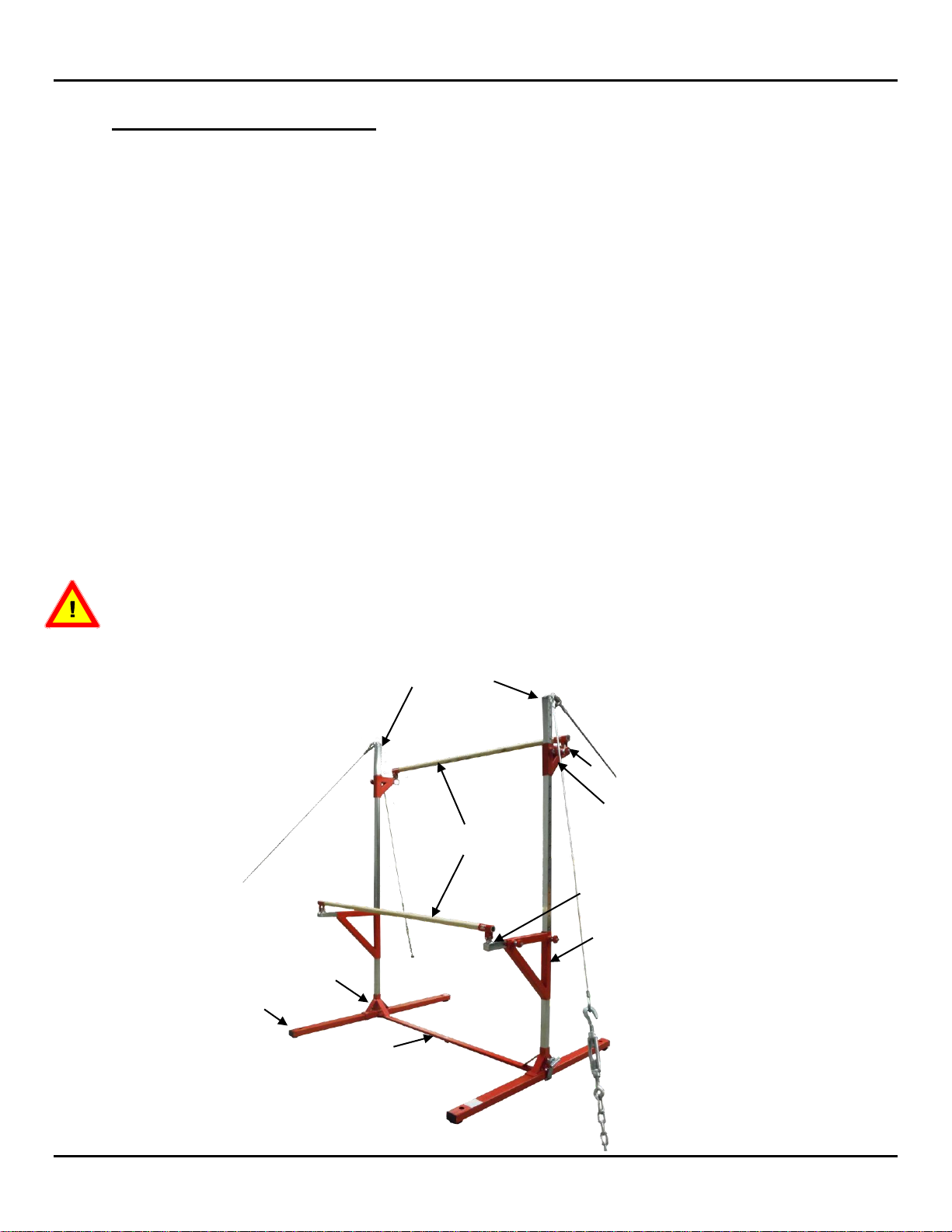
1. Apparatus description
The SPIETH America 365A Just for Kids Cantilever Bars includes the following items:
Just for Kids Bases (#355-01): 1 Pair
Cantilever Bars Short Upright bases (#355-620): 2 Pieces
oAssembled complete with clamps
Just for Kids Cross Tube (#355-361): 1 Piece
Cantilever Bars Uprights (#355-610): 2 Pieces
Cantilever Bars Low Frames, right & left (#355-630 & 631): 2 Pieces
oAssembled complete with Locking devices
Cantilever Bars Low Frame Adjusting Tubes, right & left (#355-520 & 521): 2 Pieces
Cantilever Bars High Frames, right & left (#355-640 & 641): 2 Pieces
oAssembled complete with Locking devices
Cantilever Bars High Frame Adjusting Tubes, right & left (#355-650 & 651): 2 Pieces
Just for Kids Veneered Fiberglass Rail (#355-65A): 2 Pieces
oComplete with mounting hardware
Cantilever Bars Cable Tie Down Kit (#136CT): 1 Kit
oComplete with cables, turnbuckles, Anchors & hardware
This product is designed and intended for use ONLY when cabled, using the supplied
Tie-down system. DO NOT USE THIS APPARATUS IN THE ABSENCE OF THE TIE-DOWN
SYSTEM!
355-361
355-630 & 355-631
355-65A
355-520 & 355-521
355-610
355-640 & 355-641
355-650 & 355-651
355-01
355-620
365A JFK CANTILEVER BARS Assembly Instructions
Page 4 of 13
2. Set-up, Assembly and Adjustment
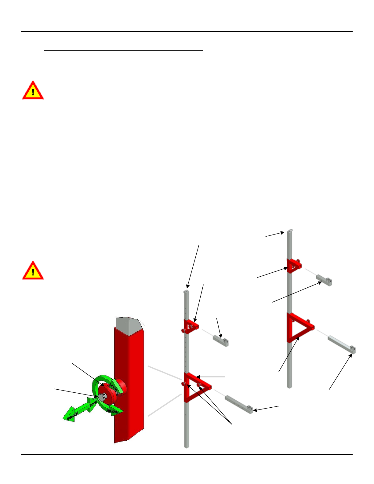
a. Cantilever Bars Uprights and Frames Assembly (#355-610)
THERE IS A TOP & LEFT / RIGHT SIDE TO THIS ASSEMBLY, so ensure that the
Locking Devices and Adjustment Holes in the Uprights face the same direction as
shown in Figure 2 below.
1. Slide the Cantilever Bars High Frames, right & left (#355-640 & 641) over each of the
Cantilever Bars Uprights (#355-610) to the desired height.
2. Then Slide the Cantilever Bars Low Frames, right & left (#355-630 & 631) over each of the
Cantilever Bars Uprights (#355-610) to the desired height, as shown on Figure 2 below. The
Cantilever Bars Low Frames can also be positionned facing the opposite way of the High Frames
(as shown on page 3), in order to increase the distance between the rails.
3. Next, insert the High and Low Frames Adjusting Tubes into the High and Low Frames as
shown in Figure 2 below.
4. Ensure that both Left and Right Hand Cantilever Bars Upright, each have a set of High and Low
Frames at the same height, and that all the Spin Snap Locks are each FULLY ENGAGED AND
TIGHTENED.
Do not insert assembled
Cantilever Bars Upright
Assemblies into the upright
Bases at this point! Follow
each assembly step in
sequence.
SPIN SNAP LOCKS
LOW FRAME
ADJUSTING TUBES
355-520 & 355-521
LOW FRAMES
355-630 & 355-631
HIGH FRAME
ADJUSTING TUBES
355-650 & 355-651
HIGH FRAMES
355-640 & 355-641
CANTILEVER BARS
UPRIGHTS
355-610
Figure 2
SPIN LOCKING HANDLE
SNAP LOCK
365A JFK CANTILEVER BARS Assembly Instructions
Page 5 of 13
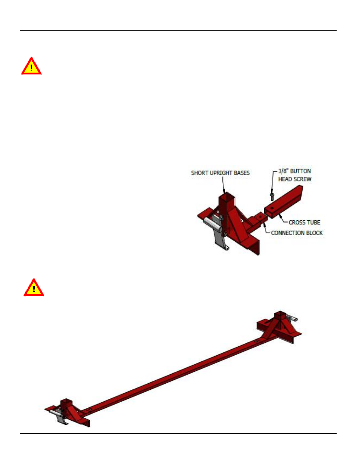
Figure 1
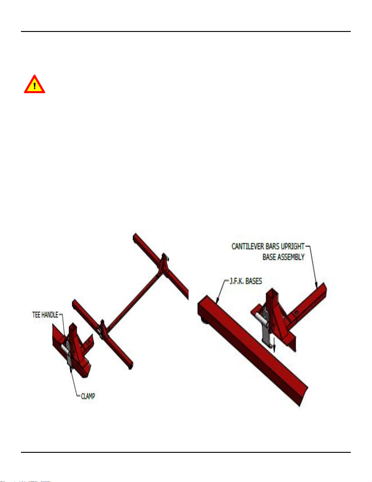
b. Cantilever Bars Short Upright bases Assembly (#355-620)
This step must be done first, before any further Assembly of your Apparatus! Ensure
the screws are tightened securely!
1. Locate the two Cantilever Bars Short Upright bases (#355-620), one Just for Kids Cross
Tube (#355-360) and the 7/32” Allen key.
2. Slide the Cross Tube over the connection block with the hole facing upwards as shown. Line up
the holes and thread the supplied 3/8” Button Head Screw into the hole. Tighten screw firmly with
a 7/32” Allen key. (Fig. 1)
3. Repeat previous step to assemble the second Cantilever Bars Short Upright base to the Cross
tube.
4. Ensure the assembly is stable before proceeding.
Refer to the subsequent sections in this “JFK” Cantilever Bars Assembly manual for
complete details on Tie-down and assembly of all other related components for this
Just For Kids Apparatus.
365A JFK CANTILEVER BARS Assembly Instructions
Page 6 of 13
Figure 3
c. Cantilever Bars Short Upright Bases Assembly to JFK Bases (#355-
01)
The following procedures will require at least two (2) qualified persons. At no time
should children or other unqualified persons undertake any part of this procedure.
1. Locate the two (2) JFK Bases (#355-01) and the Cantilever Bars Upright Bases previously
assembled (see page 4).
2. Install the Cantilever Bars Upright Bases Assembly as shown in Figure 3 below, so that the
assembly is centered on the JFK Bases.
3. With the Cantilever Bars Upright Bases Assembly centered on both JFK Bases, tighten each
clamp securely, turning the T-handle clockwise. This will secure the Cantilever Bars Upright
Bases Assembly in place (Figure 3).

365A JFK CANTILEVER BARS Assembly Instructions
Page 7 of 13
Figure 4
d. Cantilever Bars Uprights and Rails Assembly
1. Insert each Cantilever Bars Uprights and Frames assembly all the way into the Uprights Bases as
shown in Figure 4 below, until they bottom out.
Ensure the Cable Connection links point away from center and the Low Frames face in
the same direction when inserting the Assembled Cantilever Bar Uprights into the
Upright Bases as shown in Figure 4.
2. Install the rails to the High and Low Adjusting Tubes as shown in Figure 4 below.
DO NOT ATTEMPT TO USE THE APPARATUS AT THIS POINT! The Cantilever Bars must
be cabled. Proceed to the Cable Tie down Section.
365A JFK CANTILEVER BARS Assembly Instructions
Page 8 of 13
e. Installing Concrete Anchors
To determine anchor locations, please refer to the following section for your specific
equipment to be anchored.
Tools Required (customer supplied):
Tape measure
Anchor setting tool or punch with a 5/16” diameter & 1.5” long end
5/8” diameter carbide tipped concrete drill bit
Hammer drill
3/4” or 19mm Socket, Extension and Ratchet
Hammer
Shop Vacuum for fine dust
SAFETY GLASSES, TO BE WORN DURING DRILLING, ANCHOR INSTALLATION AND
SETTING!
NEVER PLACE A FLOOR ANCHOR INTO A SEAM/CRACK, OR AN AREA WITHIN 9”
FROM A SEAM/CRACK OR OUTSIDE EDGE OF THE CONCRETE FLOOR.
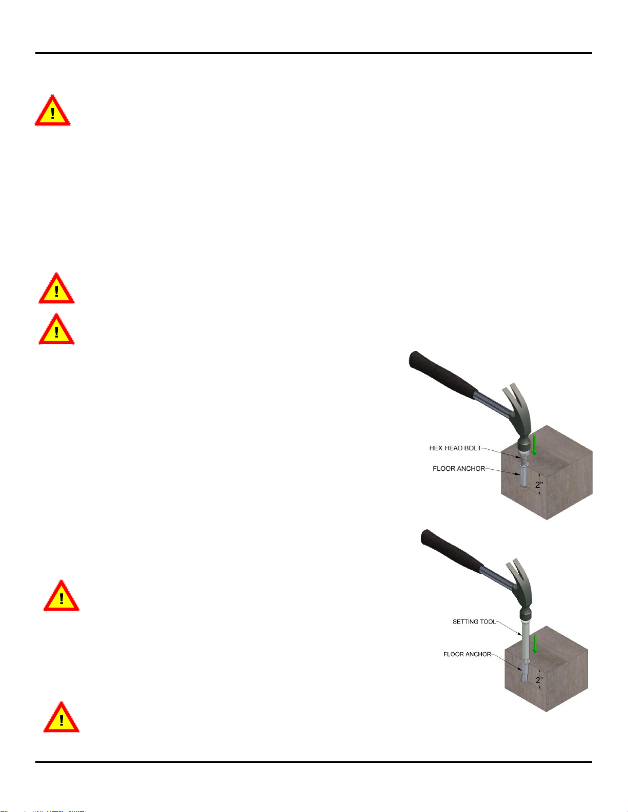
1. With the 5/8” carbide drill bit installed in the Hammer drill, drill
a hole into the concrete to 2 inches depth (+1/8”).
2. Use a shop vacuum or turkey baster to remove all dust and
concrete chips out of the holes. Ensure the hole depth is at
least 2 inches (+1/8”).
3. Turn a hex head bolt 3 full turns into a floor anchor, and insert
it into the drilled hole (Fig. 5).
4. Use the hammer to tap the top of the bolt until the floor anchor
is flush with or just below the top of the concrete (Fig. 5).
5. Remove the hex head bolt, proceed to set the anchor and lock
it in place.
THE STEP OF LOCKING OR SETTING THE ANCHORS
IS CRITICAL. ENSURE THAT IT IS DONE CORRECTLY
(FIG. 6)!
6. Using a punch or setting tool (customer supplied), set the floor
anchor by striking the plunger in the center of the floor anchor.
Strike the setting tool or punch with a hammer repeatedly, to
expand the anchor in the hole (Fig. 6).
WHEN SECURING EQUIPMENT TO FLOOR ANCHORS
USING BOLTS, A TORQUE VALUE OF 20 FT LBS IS RECOMMENDED.
Fig. 5
Fig. 6
365A JFK CANTILEVER BARS Assembly Instructions
Page 9 of 13
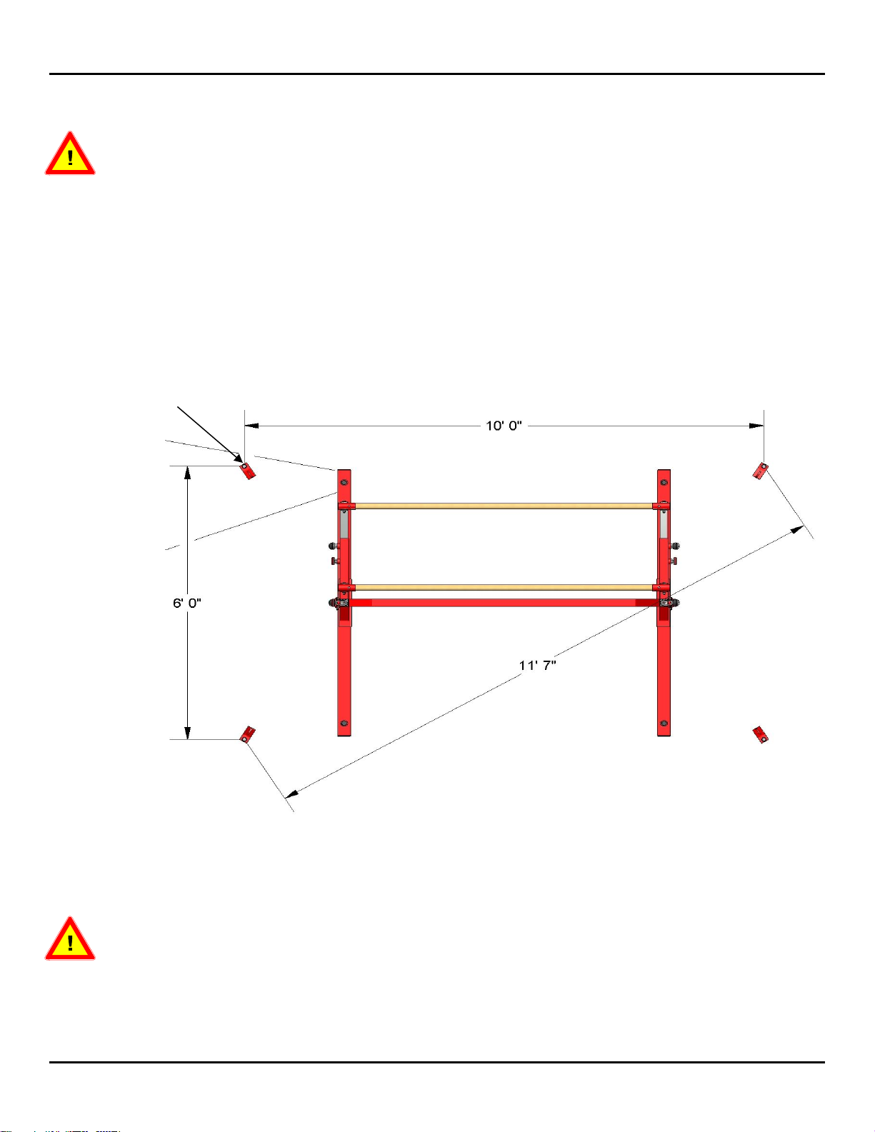
Figure 7
THREADED SOCKET ADAPTORS (4)
f. Cable Tie-Down Floor Anchors Installation
4 anchors in total are required for this apparatus. Drill & install anchors as described on
page 8.
1. Mark out the location of the 4-Cable Tie-down anchors using the dimensions shown in Figure 7
below. Use the Diagonal Measurement (11’ 7”) to ensure the 4 anchors are square to each other.
Drill and install floor anchors into concrete (See previous page for instructions on anchors
supplied by SPIETH America or follow the manufacturer’s instructions if anchors are purchased
elsewhere.
2. Install the 4 supplied Threaded Socket Adaptors.
ENSURE THE CABLE ANCHORS ARE PROPERLY SET OR THE SAFE USE OF THE EQUIPMENT
MAY BE COMPROMISED!
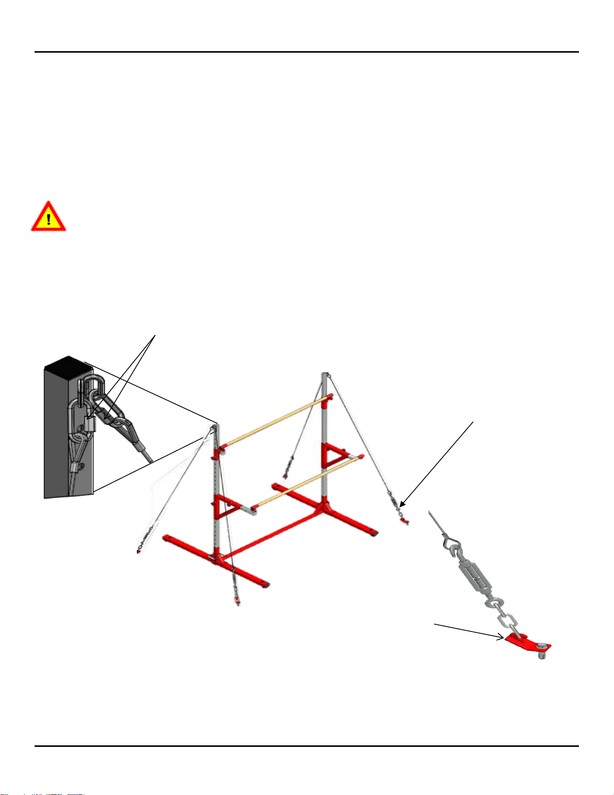
3. Attach two (2) tie-down cables to the top of each Cantilever Bars Upright, using the supplied
quick links (see Figure 8 below). Tighten Quick Links using an adjustable wrench.
365A JFK CANTILEVER BARS Assembly Instructions
Page 10 of 13
4. Attach one turnbuckle chain end to each Threaded Socket Adaptors (Fig. 8). Tighten Quick
Links using an adjustable wrench.
5. Open the turnbuckles and attach each turnbuckle hook end to the corresponding tie-down cable
(Fig. 8).
6. Once all 4 cables are connected properly, the cables can be tightened using the turnbuckles.
Tighten each Turnbuckle equally, so that the uprights remain perpendicular to the floor. See
next section for complete instructions on rail and turnbuckle adjustments.
Do not over tighten the turnbuckles as this may warp or damage the uprights (see notes
on next page about Cantilever Bars Adjustment).
Figure 8
QUICK LINKS SHOULD BE ORIENTED
SO THEY WILL BE TIGHTENED BY
TURNING THE NUT DOWN
TURNBUCKLE
TURNBUCKLE CONNECTION
TO THREADED SOCKET
ADAPTORS

365A JFK CANTILEVER BARS Assembly Instructions
Page 11 of 13
g. Rail Height and Width Adjustment
To adjust the height or width of either the Low or High Rail, first loosen the turnbuckles. When
adjustment is done, ALWAYS RETIGHTEN THE 4 TURNBUCKLES EQUALLY,so that the
apparatus Uprights remain perpendicular to the floor. Also check the alignment of the 2 Uprights in
comparison to each other.
2.7.1. Low or High Rail Height Adjustment
Choosing the desired Low or High Frame, loosen the Spin Locking handle on the Cantilever Bars
Upright and WHILE SUPPORTING THE RAIL, pull the Snap Lock and move the rails up or
down to the desired location. Let the Snap Lock snap into a hole on the Cantilever Bars Upright
and tighten the Spin Locking Handle to secure it in place. (Fig. 9)
2.7.2. Rail Width Adjustment
Only the Low Rail Adjusting Bracket can be adjusted to change the width between the Rails. Loosen
the Spin Locking handle on the Low Frame Adjusting Tube and WHILE SUPPORTING THE RAIL,
pull the Snap Lock and move the rail to the desired location. Let the Snap Lock snap into a hole
on the Adjusting Tube and tighten the Spin Locking Handle to secure it in place. (Fig. 9)
DO NOT tighten Turnbuckles to the point that the cables are taught or springy! This
WILL NOT make the bars work better! It will only add pressure to the connecting points.
If the cables are over-tightened, twisting of the Cantilever Uprights may occur which will
make height adjustment of rails more difficult and may result in permanent damage to
the Uprights.
Ensure all Clamps and Spin Snap Locks are fully engaged and tightened prior to using
the equipment.
SPIN LOCKING HANDLE
SNAP LOCK
Figure 9
365A JFK CANTILEVER BARS Assembly Instructions
Page 12 of 13
3. Spare parts
Description
Part Number
1 Piece –Just for Kids Spin-Snap Lock
(Combination of Locking Handle and Snap Lock)
P355-254A
1 Piece –Just for Kids Clamp
P355-248A
1 Piece - Just for Kids Veneered Fiberglass Rail
355-65A
1 Pair –Just for Kids Base Foot Pad
P355-BFP
1 Pair –Just for Kids Base End Cap
P355-BEC
1 Kit –Just For Kids Cantilever Bars Tie-Down
No image available
136CT
1 Set –Just For Kids Cantilever Bars Low Frame
Add-on
(Includes 2 Low Frames & Adjusting Tubes + 1
Veneered Fiberglass Rail)
Allows to add one supplementary rail to the
Cantilever Bars or to replace the Small High
Frame, to increase the width between rails.
No image available
365A-01

365A JFK CANTILEVER BARS Assembly Instructions
Page 13 of 13
4. SAFETY
WARNING
Any activity involving motion or height creates the possibility of serious injury including
permanent paralysis and even death from landing or falling on the neck, head or other parts of
the body.
You assume the risk of serious injury in using this equipment. However, the risk can be
reduced by strictly following these rules at all times.
1. This equipment is designed and intended for use only by the beginner level gymnasts
under a weight of 150 lbs (68 kg).
2. Use this equipment only under the supervision of a trained and qualified instructor.
3. This equipment must be used only when protected by proper matting as recommended by
the Federation of International Gymnastics (F.I.G.). If in doubt, concerning proper matting,
do not use this equipment.
4. This equipment must be used with proper spotting equipment and qualified spotters
suitable to the activity or skill. Always consult an instructor.
5. Know your own limitations and the limitations of this equipment. Follow progressive learning
techniques and always consult an instructor.
6. Always inspect this equipment for proper stability before each use.
7. Always inspect this equipment for loose fittings and parts. Replace any worn, defective or
missing parts.
8. Always inspect this equipment for improper or unsafe installation. If in doubt, do not use
this equipment.
Table of contents
Other SPIETH Accessories manuals


Popular Accessories manuals by other brands

Heitronic
Heitronic 500662 Installation and operating instructions

Grixx
Grixx POWERBANK 20.000mAh PD manual

LEGRAND
LEGRAND Wattstopper CI-300 manual

Elenco Electronics
Elenco Electronics AK-200 Assembly and instruction manual

Valeport
Valeport Hyperion 0901001 operating manual

sunsation
sunsation SUN 3000 installation guide


