Pantone 1375 C
RGB: 255, 158, 27
CMYK: 0, 38, 89, 0
HEX: #FF9E1B
Gray 49%
Sunsation Instructions Manual 9
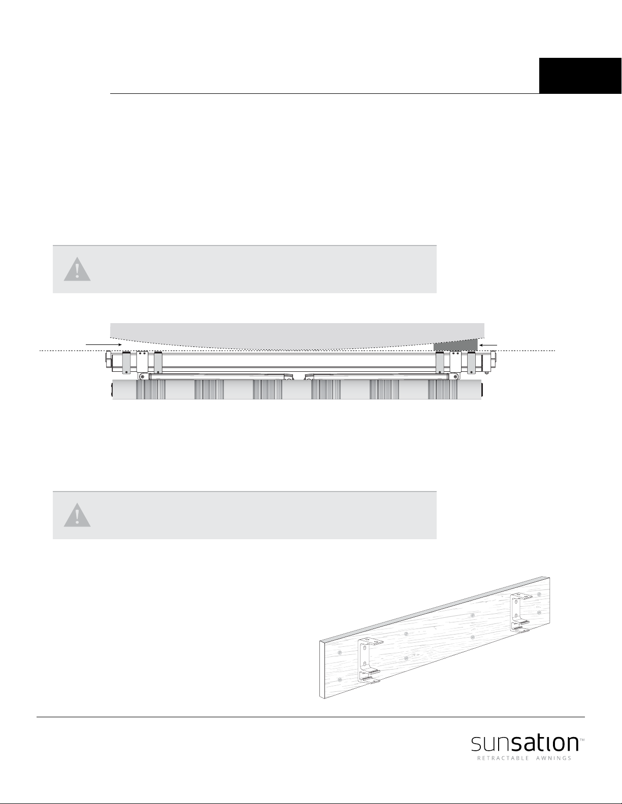
Repeat the same operation on the other side so that the front bar is absolutely leveled.
Standard arm control
1. Use the open-end wrench (13 mm)
to release the side bolt (Picture 3)
Do NOT unscrew bolts completely.
2. With the Allen key (6 mm), screw
or unscrew the bolt to the desired
angle (Picture 4).
3. Use the open-end wrench to lock
the side bolt (Picture 3).
Self-pitch arm control
1. Use the open-end wrench (13 mm)
to release the side bolt (Picture 1),
Do NOT unscrew bolts completely.
2. Use the self-pitch handle to adjust
to the desired angle (Picture 2).
3. Use the open-end wrench to lock
the side bolt (Picture 1).
Pitch adjustment (Arm control)
After the awning has been installed, making sure all bolts have been tightened and packing
materials removed, extend the awning to its full projection. The folding arms will still be
slightly angled. Hold the arm of the awning with one hand or shoulder to remove pressure
while doing the adjustment with the other hand.
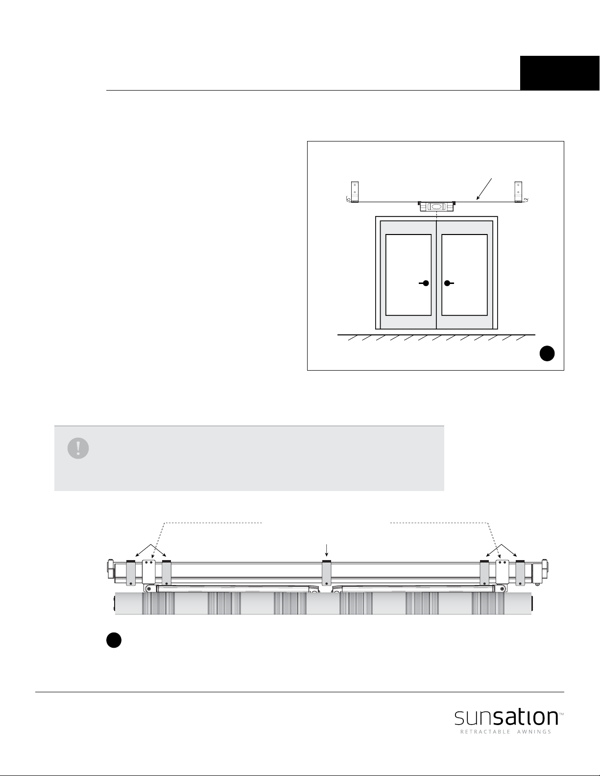
A level is added to each arm where it is attached to the front prole, this unique addition
makes installing your awning easy and accurate within minutes.
Setting the correct pitch is one of the most important details to protect the
Awning from rain damage. The more that you pitch the awning, the less water
will gather on your awning.
2
4
1
3