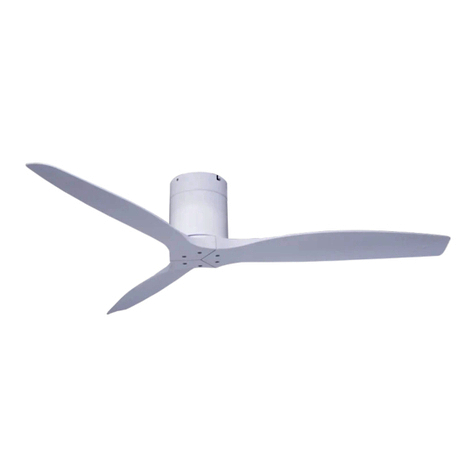
Spin ONIX SP960 User manual

INSTALLATION MANUAL
SP960 | SP972 | SP984
SP933 | SP984AL
ONIX

Installation Manual
SPIN © 2017
Model No. SP960
SP972
SP 984
SP933
SP984AL
SPIN and its logo are all trademarks of SPIN Pte Ltd and registered in Singapore. The content in this manual is
subjected to change without prior notice. All content are accurate and correct at the time of publishing.
Thank you for purchasing SPIN ceiling fans. Please take some time to register your product with us by mailing
in the warranty card or register online at www.spinfans.com.sg
CCONTENTSONTENTS
Precautions Wiring
Supplied Parts
Pairing of Remote Control
Troubleshooting
Functions
SPIN Customer Care
Mounting Bracket Installation
Attaching the Safety Wire
Downrod Assembly
Hanging the Fan
Installing the Blades
Base Plate / LED Light Installation
INSTALLATION STEPS
REMOTE CONTROL
POST INSTALLATION
110
3
11
13
12
14
4
5
6
7
8
9

| © 2017 ONIX Installation Manual |
1 2
PRECAUTIONSPRECAUTIONS
1. To ensure the success of the installation, be sure to read the instructions and study the diagrams thoroughly before commencing.
2. All electrical work should only be undertaken after disconnection of the power by removing fuses or turning off the circuit breaker to
ensure all pole isolation of the electrical supply. If you are in any doubt the services of qualified electrician should be sought to ensure
that all work is carried out in accordance with the l.E.E. Regulations and local wiring regulations, current good practice and other
national and local electrical codes.
3. Make sure that your installation site will not allow the rotation fan blades to come into contact with any object and that there is
minimum clearance of 150mm (6”) from the blade tip to the wall or ceiling. Please note that the bigger this clearance is, the better
the airflow from your fan will be. Ensure the blades are mounted at a height of more than 2.3 meters from the floor when the fan is
installed.
4. The fixing point for the fan must be able to support a weight of ten times that of the net weight of the fan. Net weight can be found
on the bottom of the unit’s box. The moving weight of the fan must not twist or work loose. For safety and best operating results, you
must have a qualified electrician to assemble and install your fan.
5. This appliance is not intended for use by persons (Including children) with reduced physical, sensory or mental capabilities, or lack
of experience and knowledge, unless they have been given supervision or instruction concerning use of the appliance by a person
responsible for their safety. Children should be supervised to ensure that they do not play with the appliance.
6. The fan must be earthed and should be installed with a double pole single throw switch (Breaker Switch) with minimum 3mm contact
gap in the fixed installation circuit.
7. Do not connect the fan motor to a dimmer switch. This may give an unsatisfactory performance (motor hum) and cause damages to
the motor. This will void the warranty.
8. It is not recommended that ceiling fans and gas appliances be operated in the same room at the same time.
9. After the fan is completely installed, make sure that all connections are secured tightly to prevent any problems.
10. Because of the fan’s natural movement, some connections may loosen. Check the support connections, brackets and blade
attachments twice a year to make sure they are all secure. If they are loose, tighten with a screwdriver (It is no necessary to take the
fan down from the ceiling).
11. This fan is only compatible with SPIN lighting products and remote control.
12. Do not insert anything into the fan blades while the fan is in operation. This will damage the blades and upset the balance of the
unit causing the unit to wobble.
13. For extra safety, contact SPIN Customer Care when in doubt with installation and check the fan every year to make sure there are
no loose parts.
14. It is recommended for all customers to contact SPIN Customer Care for an inspection of the fan parts and its suspension once every
two years. Fees may apply accordingly.

| © 2017 ONIX Installation Manual |
3 4
SUPPLIED PARTSSUPPLIED PARTS
A
B
A
B
C
D
E
F
G
H
I
J
K
L
M
N
O
P
C
D
E
F
G
H
I
J
K
L
M
N
OP
Mounting Bracket
Expansion Screw (x4) and “J” Hook (x1)
Downrod (Rod Ball, Down Rod, Cross Pin, Cotter Pin)
Ceiling Canopy
Canopy Screw Cover
Coupling Cover
Receiver
Motor
Blade Cover Set
Blade (Length variations based on model)
Blade Holder Set
Base Plate
LED Light Panel (Optional)
LED Light Cap (Optional)
Remote
Bag of Screws
INSTALLATION STEPSINSTALLATION STEPS
1. MOUNTING BRACKET INSTALLATION
Secure the Mounting Bracket to the concrete ceiling with
the 4 expansion screws included.
! NOTE: After securing the mounting bracket, please ensure
that it is able to bear a minimum tension of 30kg to
make sure it’s safe for operation.
Expansion Screws x4 (Front & Back)
Concrete Ceiling
Mounting Bracket
Speed
Timer
h
Speed Light

| © 2017 ONIX Installation Manual |
5 6
INSTALLATION STEPSINSTALLATION STEPSINSTALLATION STEPSINSTALLATION STEPS
2. ATTACHING THE SAFETY WIRE
Drill an approproate size hole into the ceiling that
would fit the expansion screw with a “J” hook.
Secure the screw into the ceiling and attach
the safety wire to the “J” hook, as shown in the
diagram:
Tighten the screw after the rope is attached
securely.
Safety Wire
Downrod Rod
Expansion Screw
with “J” Hook
Expansion Screw
with “J” Hook
Electrical Wire
Downrod
Ceiling Canopy
Motor Cover
Downrod Rod
Cross Pin
Screw
Screw
Enlarged Figure
Enlarged Figure
Cotter Pin
Safety Wire
3. DOWNROD ASSEMBLY
Study the diagram below before you assemble the downrod. Insert the downrod through the ceiling canopy and receiver
coupling cover. Direct the electrical wire through the downrod. Align the two holes of the downrod with the two holes on
the yoke collar. Insert the cotter pin through the holes and insert the cross pin to secure. Tighten the two screws on the
side after.

| © 2017 ONIX Installation Manual |
7 8
INSTALLATION STEPSINSTALLATION STEPSINSTALLATION STEPSINSTALLATION STEPS
4. HANGING THE FAN
Hang the fan onto the hanger bracket following the illustration below. Insert the downrod into the slot in the mounting
bracket, rotate the downrod and align the groove on the rod ball with the groove on the mounting bracket.
Mounting Bracket
Screws
Screws
Blade Cover
Blade
5. INSTALLING THE BLADES
To assemble the blades, fasten three screws following the diagram as shown:
Blade Holder
Blade Holder Plate
Lug Groove
Power L Wire Power L Wire
Power N Wire Power N Wire
To secure the ready blades onto the blade holder plate, fasten the blade holders to the holes at the bottom of the plate
with the screws provided.

| © 2017 ONIX Installation Manual |
910
INSTALLATION STEPSINSTALLATION STEPS
6. BASE PLATE / LED LIGHT INSTALLATION
If you are not installing any LED light, you can now attach the base plate to the fan body by locking it in a clockwise
direction.
If you are installing an LED light, please follow these steps:
1. Output live wire connect with light’s live wire.
The output neutral wire connects with the light’s
neutral wire.
2. Align the three screws of the throught the light
plate and the light, rotate the plate to lock the
screws and tighten them.
Light Cover
Light Plate Lug
Light Plate
Input Light NOrange Wire
Output Light LBlue Wire
WIRINGWIRING
Insulating sleeve
Current carrying wires
Motor shaft
Safety cord
Earth wire
Cross bolt
Locking nut
Locking pin
DC MOTOR
LED
YELLOW GREEN
GROUND
CONNECTOR BLOCK
BLUE
AC IN N
AC IN L
BROWN
BLUE
BROWN
ORANGE / LIGHT
BLUE / LIGHT
YELLOW / MOTOR
BROWN / MOTOR
RED / MOTOR
PURPLE / MOTOR
BROWN / MOTOR
PINK / MOTOR
Optional LED Lightkit
installation
Wires should not be under any stress after installation.
Ensure that the wires are not compromised within the droprod, if
the fan is being suspended by a droprod.

| © 2017 ONIX Installation Manual |
11 12
REMOTE CONTROLREMOTE CONTROL REMOTE CONTROLREMOTE CONTROL
Speed
Forward / Reverse Function: Press and hold to toggle between each mode.
Natural wind mode: Turn on / off Natural Wind function.
Fan Power Button: Turn on / off the fan.
LED Tone Switch: Toggle between the three LED tones - Cool, Day and Warm.
LED Light On Button: Turns On the LED light.
LED Light Off Button: Turns Off the LED light.
Speed Buttons: Adjust fan speed.
Increase fan speed
Decrease fan speed
Timer Function: Set the timer option with a single press of the button (between 1 hour
to 9 hours). Press and hold to turn off the timer.
Pairing of Remote Control
Firstly, ensure the power supply to the ceiling fan is switched off and the remote is not in use.
Switch on the power to the ceiling fan, you should hear a “beep”. Within 3 seconds, press the Power Button to
switch on the fan.
Proceed to press the Timer Button . Upon completing these steps, you will hear a long “beep” from the receiver.
This signals that the remote control has been paired successfully.
However, if you do not hear the long “beep”, please switch off the power source to the ceiling fan and repeat the
above steps again.
Do bear in mind you have to start the pairing within 3 seconds of switching on the ceiling fan’s power source.
Speed
Timer
h
Speed Light

| © 2017 ONIX Installation Manual |
13 14
SPIN CUSTOMER CARESPIN CUSTOMER CARETROUBLESHOOTINGTROUBLESHOOTING
Should you face any difficulties resolving any problems, please contact our SPIN’s dedicated Customer Care.
SPIN Customer Care
Service Centre : 6298 1038
Operating hours : Monday - Friday | 10am - 5pm
PROBLEM Failure to operate
PROPOSED
SOLUTION(S)
Check power supply is turned on.
Check if fan wiring is correct.
Check if the wiring of the remote control's receiver is correct.
Check if remote control's batteries are installed properly.
PROBLEM Unable to control speed and/or light.
PROPOSED
SOLUTION(S)
Check if the wiring of the remote control's receiver is correct.
Check if remote control's batteries are working and installed
properly.
! WARNING: Failure to turn off the power supply prior to troubleshooting any electrical wiring may result in serious injury.

NOTESNOTES

SPIN Pte Ltd
1 Tampines North Drive 1 #04-15 T-Space S528559
T | 6298 1038 F | 6298 0780
www.spinfans.com.sg
ONIX
This manual suits for next models
4
Table of contents
Other Spin Fan manuals
Popular Fan manuals by other brands

Glen Dimplex
Glen Dimplex DHW 300VD+ Installation and operating instruction

HELLER
HELLER WAL40R instruction manual

Linea 2000
Linea 2000 DOMO DO8131 Instruction booklet

Panasonic
Panasonic F-M14E2 Operating and installation instructions

Klarstein
Klarstein 10032344 user manual

Arpo BV
Arpo BV AQUA2GO LB-SY1702 user manual