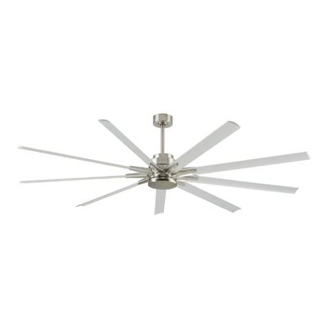
Spin SIGNATURES User manual

INSTALLATION MANUAL
SP103 • 43” |52” |60”
SIGNATURES | TIMBER

Installation Manual
SPIN © 2019
Model No. SP103 (43”/ 50”/ 60”)
SPIN and its logo are all trademarks of SPIN Pte Ltd and registered in Singapore. The content in this manual is
subjected to change without prior notice. All content are accurate and correct at the time of publishing.
Thank you for purchasing SPIN ceiling fans. Please take some time to register your product with us by mailing in the
warranty card or register online at www.spinfans.com.sg
CCONTENTSONTENTS
Precautions Wiring
Supplied Parts
Pairing of Remote Control
Warranty
Troubleshooting
Functions
SPIN Customer Care
Mounting Bracket Installation
Attaching the Safety Wire
Hanging the Fan
Hanging the Fan
Installing the Blades
Base Plate / LED Light Installation
INSTALLATION STEPS
REMOTE CONTROL
POST INSTALLATION
POST INSTALLATION
110
3
11
13
15
12
16
4
5
6
7
8
9

| © 2019 SPIN SIGNATURES Installation Manual |
1 2
PRECAUTIONSPRECAUTIONS
1. To ensure the success of the installation, be sure to read the instructions and study the diagrams thoroughly before commencing.
2. All electrical work should only be undertaken after disconnection of the power by removing fuses or turning off the circuit
breaker to ensure all pole isolation of the electrical supply. If you are in any doubt the services of qualied electrician should be
sought to ensure that all work is carried out in accordance with the l.E.E. Regulations and local wiring regulations, current good
practice and other national and local electrical codes.
3. Make sure that your installation site will not allow the rotation fan blades to come into contact with any object and that there is
minimum clearance of 150mm (6”) from the blade tip to the wall or ceiling. Please note that the bigger this clearance is, the better
the airow from your fan will be. Ensure the blades are mounted at a height of 2.3 meters (7’6“) from the oor when the fan is
installed.
4. The xing point for the fan must be able to support a weight of ten times that of the net weight of the fan. Net weight can be
found on the bottom of the unit’s box. The moving weight of the fan must not twist or work loose. For safety and best operating
results, you must have a qualied electrician to assemble and install your fan.
5. This appliance is not intended for use by persons (Including children) with reduced physical, sensory or mental capabilities, or lack
of experience and knowledge, unless they have been given supervision or instruction concerning use of the appliance by a person
responsible for their safety. Children should be supervised to ensure that they do not play with the appliance.
6. The fan must be earthed and should be installed with a double pole single throw switch (Breaker Switch) with minimum 3mm
contact gap in the xed installation circuit.
7. Do not connect the fan motor to a dimmer switch. This may give an unsatisfactory performance (motor hum) and cause damages
to the motor. This will void the warranty.
8. It is not recommended that ceiling fans and gas appliances be operated in the same room at the same time.
9. After the fan is completely installed, make sure that all connections are secured tightly to prevent any problems.
10. Because of the fan’s natural movement, some connections may loosen. Check the support connections, brackets and blade
attachments twice a year to make sure they are all secure. If they are loose, tighten with a screwdriver (It is no necessary to take
the fan down from the ceiling).
11. This fan is only compatible with SPIN lighting products and remote control.
12. Do not insert anything into the fan blades while the fan is in operation. This will damage the blades and upset the balance of the
unit causing the unit to wobble.
13. For extra safety, contact SPIN Customer Care when in doubt with installation and check the fan every year to make sure there
are no loose parts.
14. SPIN recommends a thorough examination of the fan and its suspension once every two years, by the brand’s service team.
Service fees may apply accordingly.

| © 2019 SPIN SIGNATURES Installation Manual |
3 4
SUPPLIED PARTSSUPPLIED PARTS
A
A
B
C
D
E
F
I
G
J
H
K
B
C
D
E
F
IJK
G
H
Mounting Bracket (Hugger)
Set of Expansion Screws (x3) and a “J” Hook
Motor Hub
SPIN Air Foil
Set of Blade Screws (x6)
Optional
For Extension Rod Installation
LED light plate
Mounting Bracket (Downrod)
Tri-light LED Driver
Canopy
Tri-light LED Cover
Downrod
INSTALLATION STEPSINSTALLATION STEPS
1A. MOUNTING BRACKET (HUGGER) INSTALLATION
Secure the Mounting Bracket to the concrete ceiling with
the 3 expansion screws and the “J” hook screw included.
! NOTE: After securing the mounting bracket, please ensure
that it is able to bear a minimum tension of 30kg to
make sure it’s safe for operation.
1B. MOUNTING BRACKET (DOWNROD) INSTALLATION
Secure the “U” shape Mounting Bracket to the concrete ceiling
with the 3 expansion screws and the “J” hook screw included.
Concrete Ceiling
Expansion Screw x3 “J” Hook
Expansion Screw
Expansion Screws x 1
(Front & Back)
Expansion Screws x 2
(Front & Back)
Safety Cord
Concrete Ceiling
Mounting Bracket
Downrod
Expansion
Screw
with "J" Hook

| © 2019 SPIN SIGNATURES Installation Manual |
5 6
INSTALLATION STEPSINSTALLATION STEPSINSTALLATION STEPSINSTALLATION STEPS
2. ATTACHING THE SAFETY WIRE
After securing the expansion screw with “J” hook into
the ceiling, attach the safety wire to the “J” hook, as
shown in the diagram:
Tighten the screw after the rope is attached securely.
3A. HANGING THE FAN (HUGGER)
If you are installing the fan with the hugger unit bracket, follow the illustrations below to attach the motor hub (fan’s body) to the
mounting bracket installed in Step 1. Turn the motor hub to align the holes on the body and the mounting bracket.
Fasten the motor hub to the bracket with the screws (x4) provided and ensure the motor hub is fastened securely.
Safety Wire
Safety Wire
Blue
Brown
Green/Yellow
(Earth Wire)
Safety Wire
Expansion Screw
with “J” Hook
Expansion Screw
with “J” Hook

| © 2019 SPIN SIGNATURES Installation Manual |
Lug Groove
Power L Wire
Power N Wire
7 8
INSTALLATION STEPSINSTALLATION STEPSINSTALLATION STEPSINSTALLATION STEPS
3B. HANGING THE FAN (DOWNROD)
Hang the fan onto the “U” mounting bracket following the illustration below. Insert the downrod into the slot in the mounting
bracket, rotate the downrod and align the groove on the rod ball with the groove on the mounting bracket.
4. INSTALLING THE BLADES
To assemble the blades, fasten three screws following the diagram as shown:
1
2

| © 2019 SPIN SIGNATURES Installation Manual |
9 10
INSTALLATION STEPSINSTALLATION STEPS
5. LED LIGHT INSTALLATION
If you are not installing any LED light, you have completed the installation of your new SPIN fan.
If you are installing an LED light, please follow these steps:
1. Attach the LED light plate to the fan (with the blades installed)
2. Once the LED light plate is in place, proceed to lift the LED light driver
to the plate and fasten it securely.
3. Lock the LED light cover by rotating it in a clockwise direction.
Wires should not be under any stress after installation.
Ensure that the wires are not compromised within the droprod, if
the fan is being suspended by a droprod.
WIRINGWIRING
1
2
3
Insulating Sleeve
Cross Bolt
Locking Pin
Locking Nut
Earth Wire Safety Wire
Downrod
Current Carrying Wires
Signal Wire
Red
Brown
Black
White
Ye l l ow
Ye l l ow
Brown
Blue
Ye l l ow G re en
(Earth)
RECEIVER
MOTOR POWER
SUPPLY
LED LIGHT
(Optional)

| © 2019 SPIN SIGNATURES Installation Manual |
11 12
REMOTE CONTROLREMOTE CONTROL REMOTE CONTROLREMOTE CONTROL
LED Indicator
Off Button
Forward / Reverse Function
Speed Option
Natural Wind Mode
LED Light Dimmer Buttons
LED Light Dual Function Buttons
Decrease Brightness
Press Once:
On/Off LED Light
Press & Hold:
Tune the colour of the
LED light gradually
(Cooler Tone)
Press Once:
Switch Colour Tone of LED
Light (Day, Cool & Warm)
Press & Hold:
Tune the colour of the
LED light gradually
(Warmer Tone)
Increase Brightness
LED Light On/Off (Press Once )
LED Light Colour Tuning (Press & Hold)
LED Light Colour Switch (Press Once )
LED Light Colour Tuning (Press & Hold)
Timer Function (2 or 6 hours)
PAIRING OF REMOTE CONTROL
Firstly, ensure the power supply to the ceiling fan is switched off and the remote is not in use.
Switch on the power to the ceiling fan and complete the pairing process within 5 seconds.*
Press and hold the Off Button for 5 seconds or more until you hear a short “beep” sound.
This signies that the pairing is complete and the fan can now be used.
However, if you do not hear the “beep”, please switch off the power source to the ceiling fan (for at least 10 minutes) and repeat
the above steps again.
*Do bear in mind you have to start the pairing within 5 seconds of switching on the ceiling fan’s power source.

| © 2019 SPIN SIGNATURES Installation Manual |
WARRANTYWARRANTY
Thank you for purchasing our product. We at SPIN Pte Ltd (“SPIN”) are committed to deliver you our customers (“Customer”) with carefully
manufactured products. This product (“Product”) has been tested and is in perfect working condition at the time of delivery.
1. Requirements
1.1 The Customer is required to register this limited warranty (“Warranty”) within 10 days from the date of original purchase (“Purchase”) by
(a) sending the lled up Warranty card by post to Spin’s address at 1 Tampines North Drive 1 #04-15 T-Space Singapore 528559 ; OR
(b) online registration using the following link www.spinfans.com.sg (and attaching the proof of Purchase at Spin’s discretion. The preferred mode of
registration shall be duly updated by Spin from time to time.
1.2 Spin reserves its right to require the presentation of the original Warranty card and proof of Purchase. Spin reserves its right to void the Warranty
in case of altered, defaced or incomplete Warranty card. (where applicable)
2. Coverage
2.1 This Warranty covers (a) faulty materials and (b) manufacturing defects for a period of 1 year from Purchase (except for the fan motor which comes
with 10 years warranty). (“Warranty Period”) Spin reserves its right to inspect and test the Product for the purpose of determining the extent of any
defect and the validity of any claim made under this Warranty.
2.2 This Warranty covers purchases only in Singapore through Spin or its authorised dealers. The Warranty does not extend to Products purchased
through Carousell, Lazada, or other internet-based auction or retail sites or mobile applications.
2.3 This Warranty is applicable only to the original purchaser and is non-transferable, non-negotiable and cannot be assigned to any third party.
2.4 The installation of the Product must follow our instruction manual. Otherwise, the Warranty shall be void. This Warranty does not cover any noise
or sound as a result of improper fan installation(s) on false ceiling. For installation of Products above 10 feet high, the Customer is required to pay
an additional fee for the Warranty.
2.5 The Product must be maintained in its original point of installation for the validity of the Warranty. Successive transfers of the Product may result
to damage to the Product and its component.
2.6 The serial number of the Product must not be tampered with, erased, defaced or altered, otherwise the Warranty shall be void.
2.7 During the Warranty Period and subject to its verication, Spin will: a) Repair or replace the affected component(s) of any defective motor, spare
parts, or accessories; and b) Repair or replace the defective part(s). In case of replacement of the affected component(s) or defective part(s), the
said component(s) or part(s) shall become Spin’s property. For the avoidance of doubt, replacement of the Product to a new Product is only proper
in cases where Spin deems the Product as irreparable. Rest assured, in all instances, Spin will exert its best efforts to repair the Product back to its
working condition.
3. Exclusions
3.1 This Warranty does not cover the following:
a) due to normal wear and tear;
b) scratches, corrosion, rust, colour deteriorations, stains, dents, cracks, noise, balancing of fan, switch control, lighting bulbs, power point and
power plug;
c) Product serviced or repaired other than by Spin or its authorised representative;
d) Product replaced with components and parts not supplied by Spin;
e) malfunction, losses, defects, or damage resulting from acts of god, civil unrest and or accidents;
f) malfunction, losses, defects, or damage resulting from tampering, mishandling, improper installation, improper use (including failing to do
reasonable and necessary maintenance), negligence and modication to the Product; or
g) obstruction caused to access of electrical part(s)/product(s) (e.g. ceiling board / false ceiling);
h) damage caused by connecting the product to a dimmer, regulator, or IC control.
4. Other Terms
4.1 Spin will bear the cost of transport and service charge only within the rst year of the Warranty Period. For servicing of the Product from second
year onwards (i.e for the fan motor Warranty), the Customer will bear the cost of transport and service charge. Spin reserves its right to impose
additional charges for dismantling and re-installation of the Product when necessary. For servicing from the second year onwards due to causes
other than fan motor defects, the Customer will bear the cost of transport, service charge and costs of components or parts.
4.2 Spin will use reasonable commercial endeavours to have all necessary spare parts available for the purpose of the Warranty. However, Spin shall not
be liable for delays due to sourcing of parts which are required or due to circumstances beyond the control of Spin.
4.3 Spin disclaims any liability for any injury or damage to person, property or animal resulting from failure to comply with our instruction manual. Spin
disclaims any liability for consequential or incidental damages, due to product failure, whether arising out of breach of warranty, breach of contract
or otherwise.
4.4 Spin’s decision on all questions relating to complaints as to defects either workmanship or materials shall be conclusive and the Customer agrees to
abide by such a decision. The Warranty stated herein shall be limited within the Warranty Period.
4.5 The ceiling fan should be checked annually for loose and/or broken parts. Spin recommends its in-house servicing team and fees may apply after the
rst year warranty ends.
4.6 It is recommended that the ceiling fan suspension should be inspected by Spin at least once every two years. Fees apply accordingly.
4.7 The terms and conditions of this Warranty shall be governed by and construed in accordance with the laws of the Republic of Singapore, and
the Customer submits to the exclusive jurisdiction of the courts of Singapore in the determination of any matter or dispute arising in connection
therewith.
Register your warranty online at www.spinfans.com.sg
13 14

| © 2019 SPIN SIGNATURES Installation Manual |
15 16
SPIN CUSTOMER CARESPIN CUSTOMER CARETROUBLESHOOTINGTROUBLESHOOTING
Should you face any difculties resolving any problems, please contact our SPIN’s dedicated Customer Care.
SPIN Customer Care
Service Centre : 6298 1038
Operating hours : Monday - Friday | 9:30am - 5:30pm
PROBLEM Failure to operate
PROPOSED
SOLUTION(S)
Check power supply is turned on.
Check if fan wiring is correct.
Check if the wiring of the remote control's receiver is
correct.
Check if remote control's batteries are installed properly.
PROBLEM Unable to control speed and/or light.
PROPOSED
SOLUTION(S)
Check if the wiring of the remote control's receiver is
correct.
Check if remote control's batteries are working and
installed
properly.
! WARNING: Failure to turn off the power supply prior to troubleshooting any electrical wiring may result in serious injury.

SPIN Pte Ltd
1 Tampines North Drive 1 #04-15 T-Space S528559
T | 6298 1038 F | 6298 0780
www.spinfans.com.sg
SIGNATURES
This manual suits for next models
2
Table of contents
Other Spin Fan manuals
Popular Fan manuals by other brands

Glen Dimplex
Glen Dimplex DHW 300VD+ Installation and operating instruction

HELLER
HELLER WAL40R instruction manual

Linea 2000
Linea 2000 DOMO DO8131 Instruction booklet

Panasonic
Panasonic F-M14E2 Operating and installation instructions

Klarstein
Klarstein 10032344 user manual

Arpo BV
Arpo BV AQUA2GO LB-SY1702 user manual