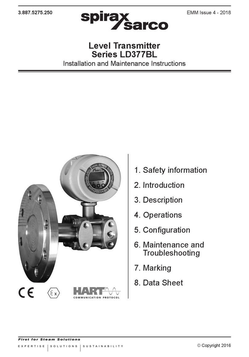
Spirax Sarco TB300 User manual

3.885.5275.200 Ed. 1.1 IT - 2012
© Copyright 2010
EXPERTISE SOLUTIONS SUSTAINABILITY
1. Safetyinformation
2. Technicalinformation
3. Commissioning
4. Troubleshooting
5. Maintenance
6. Spareparts
Torque Tube TB300
Digital Transmitters
Installation and Maintenance Instructions
The PED Directive 97/23/EC is repealed and replaced by the new
PED Directive 2014/68/EU with effect from 19 July 2016.

ATTENZIONE
Lavorare in sicurezza con apparecchiature
in ghisa e vapore
Working safely with cast iron products on steam
Informazioni di sicurezza supplementari - Additional Informations for safety
Lavorare insicurezza conprodotti
in ghisa per linee vapore
I prodotti di ghisa sono comunemente presenti
in molti sistemi a vapore.
Se installati correttamente, in accordo alle
migliori pratiche ingegneristiche, sono dispositivi
totalmente sicuri.
Tuttavia la ghisa, a causa delle sue proprietà
meccaniche, è meno malleabile di altri materiali
come la ghisa sferoidale o l’acciaio al carbonio.
Di seguito sono indicate le migliori pratiche
ingegneristiche necessarie per evitare i colpi
d'ariete e garantire condizioni di lavoro sicure
sui sistemi a vapore.
Movimentazione in sicurezza
La ghisa è un materiale fragile: in caso di
caduta accidentale il prodotto in ghisa non è
più utilizzabile. Per informazioni più dettagliate
consultare il manuale d'istruzioni del prodotto.
Rimuovere la targhetta prima di effettuare la
messa in servizio.
Working safely with cast iron
products on steam
Cast iron products are commonly found on steam
and condensate systems.
If installed correctly using good steam
engineering practices, it is perfectly safe.
However, because of its mechanical properties,
it is less forgiving compared to other materials
such as SG iron or carbon steel.
The following are the good engineering prac-
tices required to prevent waterhammer and
ensure safe working conditions on a steam
system.
Safe Handling
Cast Ironis abrittle material.If theproduct isdropped
during installation and there is any risk of damage
the product should not be used unless it is fully
inspected andpressure testedby themanufacturer.
Please remove label before commissioning

Vapore
Steam
Flusso
Flow
Esempi di esecuzioni corrette ( ) ed errate ( ) sulle linee vapore:
Steam Mains - Do's and Dont's:
Flusso
Flow
Prevenzione dai colpi d’ariete - Prevention of water hammer
Scarico condensa nelle linee vapore - Steam trapping on steam mains:
Intervalli di 30÷50 m. intervals
Pendenza - Gradient 1:100
Vapore
Steam Gruppo di scarico
Trap set
Condensa - Condasate
Pendenza - Gradient 1:100
Gruppo di scarico
Trap set
Gruppo di scarico
Trap set
Condensa - Condasate
Vapore
Steam

Prevenzione delle sollecitazioni di trazione
Prevention of tensile stressing
Evitare il disallineamento delle tubazioni - Pipe misalignment:
Installazione dei prodotti o loro rimontaggio post-manutenzione:
Installing products or re-assembling after maintenance:
Evitare l’eccessivo serraggio.
Utilizzare le coppie di serraggio
raccomandate.
Do not over tighten.
Use correct torque gures.
Per garantire l’uniformità del carico e dell'allineamento,
i bulloni delle ange devono essere serrati in modo
graduale e in sequenza, come indicato in gura.
Flange bolts should be gradually tightened across
diameters to ensure even load and alignment.

Dilatazioni termiche - Thermal expansion:
Gli esempi mostrano l’uso corretto dei compensatori di dilatzione. Si consiglia di richiedere una
consulenza specialistica ai tecnici dell’azienda che produce i compensatori di dilatazione.
Examples showing the use of expansion bellows. It is highly recommended that expert advise is
sought from the bellows manufacturer.
Guide
Guides
Distanza breve
Short distance
Punto di ssaggio
Fixing point
Movimento assiale
Axial movement
Distanza
media
Medium
distance
Tiranti limitatori
Limit rods
Piccolo
movimento
laterale
Small
lateral
movement
Piccolo
movimento
laterale
Small
lateral
movement
Ampio
movimento
laterale
Large
lateral
movement
Ampio
movimento
laterale
Large
lateral
movement
Guide
Guides
Guide
Guides
Guide
Guides
Punto di ssaggio
Fixing point
Tiranti limitatori
Limit rods
Movimento assiale
Axial movement

3.885.5275.200
2
Index
1. Safety information
2. Technical information
2.1 Description
2.2 Technical data
2.3 Mounting
2.4 Dimensions
2.5 Electrical connection
3. Commissioning
4. Troubleshooting
5. Maintenance
6. Spare parts
6.1 Orientable torque tube spare parts list
6.2 Not-Orientable torque tube spare parts list
6.3 Magnet spare parts list
6.4 Transmitter spare parts list

3.885.5275.200 3
1.SafetyInformation
Safe operation of these products can only be guaranteed if they are properly installed, commissioned,
used and maintained by qualied personnel (see Section 1.11 on this document) in compliance with
the operating instructions.
General installation and safety instructions for pipeline and plant construction, as well as the proper
use of tools and safety equipment must also be complied with.
1.1 Intended use
Referring to the Installation and Maintenance Instructions, name-plate and Technical Information
Sheet, check that the product is suitable for the intended use/application. These products comply
with the requirements of the European Pressure Equipment Directive 97/23/EC and carry the mark
when so required. It should be noted that product rated as ‘SEP’ are required by the Directive not
to carry the mark.
i) These products have been specically designed for use on steam, air or condensate /water,
which is in Group 2 of the above mentioned Pressure Equipment Directive. The products’ use
on other uids may be possible but, if this is contemplated, Spirax Sarco should be contacted
to conrm the suitability of the product for the application being considered.
ii) Check material suitability, pressure and temperature and their maximum and minimum values.
If the maximum operating limits of the product are lower than those of the system in which
it is being tted, or if malfunction of the product could result in a dangerous overpressure or
overtemperature occurrence, ensure a safety device is included in the system to prevent such
over-limit situations.
iii) Determine the correct installation situation and direction of uid ow.
iv) Spirax Sarco products are not intended to withstand external stresses that may be induced
by any system to which they are tted. It is the responsibility of the installer to consider these
stresses and take adequate precautions to minimise them.
v) Remove protection covers from all connections before installation.
1.2 Access
Ensure safe access and if necessary a safe working platform (suitably guarded) before attempting
to work on the product. Arrange suitable lifting gear if required.
1.3 Lighting
Ensure adequate lighting, particularly where detailed or intricate work is required.
1.4 Hazardous liquids or gases in the pipeline
Consider what is in the pipeline or what may have been in the pipeline at some previous time.
Consider: ammable materials, substances hazardous to health, extremes of temperature.
1.5 Hazardous environment around the product
Consider: explosion risk areas, lack of oxygen (e.g. tanks, pits), dangerous gases, extremes of
temperature, hot surfaces, re hazard (e.g. during welding), excessive noise, moving machinery.
1.6 The system
Consider the effect on the complete system of the work proposed. Will any proposed action (e.g.
closing isolation valves, electrical isolation) put any other part of the system or any personnel at risk?
Dangers might include isolation of vents or protective devices or the rendering ineffective of controls
or alarms. Ensure isolation valves are turned on and off in a gradual way to avoid system shocks.
1.7 Pressure systems
Ensure that any pressure is isolated and safely vented to atmospheric pressure. Consider double
isolation (double block and bleed) and the locking or labelling of closed valves. Do not assume that
the system has depressurised even when the pressure gauge indicates zero.
1.8 Temperature
Allow time for temperature to normalise after isolation to avoid danger of burns.
If parts made from Viton have been subjected to a temperature approaching 315°C (599°F) or higher,
it may have decomposed generating toxic fumes. Avoid any inhalation of fumes or skin contact.
If parts made from PTFE have been subjected to a temperature approaching 260°C (500°F) or
higher, they will give off toxic fumes which, if inhaled, are likely to cause temporary discomfort.
It is essential for a no smoking rule to be enforced in all areas where PTFE is stored, handled or
processed as persons inhaling the fumes from burning tobacco contaminated with PTFE particles
can develop ‘polymer fume fever’.

3.885.5275.200
4
1.9 Tools and consumables
Before starting work ensure that you have suitable tools and/or consumables available. Use only
genuine Spirax Sarco replacement parts.
1.10 Protective clothing
Consider whether you and/or others in the vicinity require any protective clothing to protect against
the hazards of, for example, chemicals, high /low temperature, radiation, noise, falling objects, and
dangers to eyes and face.
1.11 Permits to work
All work must be carried out or be supervised by a suitably competent person. Installation and
operating personnel should be trained in the correct use of the product according to the Installation
and Maintenance Instructions.
Where a formal ‘permit to work’ system is in force it must be complied with. Where there is no such
system, it is recommended that a responsible person should know what work is going on and, where
necessary, arrange to have an assistant whose primary responsibility is safety.
Post ‘warning notices’ if necessary.
1.12 Handling
Manual handling of large and/or heavy products may present a risk of injury. Lifting, pushing, pulling,
carrying or supporting a load by bodily force can cause injury particularly to the back. You are advised
to assess the risks taking into account the task, the individual, the load and the working environment
and use the appropriate handling method depending on the circumstances of the work being done.
1.13 Residual hazards
In normal use the external surface of the product may be very hot. If used at the maximum permitted
operating conditions the surface temperature of some products may reach very high temperatures
300°C (577°F). Many products are not self-draining. Take due care when dismantling or removing
the product from an installation (refer to "Maintenance" instructions).
1.14 Freezing
Provision must be made to protect products which are not self-draining against frost damage in
environments where they may be exposed to temperatures below freezing point.
1.15 Safety information specic for the product
See the specic details relating to the product in the following "Maintenance" section.
1.16 Disposal
Unless otherwise stated in the Installation and Maintenance Instructions, this product is recyclable
and no ecological hazard is anticipated with its disposal providing due care is taken.
Viton:
- Can be landlled, when in compliance with National and Local regulations.
- Can be incinerated, but a scrubber must be used to remove Hydrogen Flouride, which is evolved
from the product and with compliance to National and Local regulations.
- Is insoluble in aquatic media.
PTFE:
- Can only be disposed of by approved methods, not incineration.
- Keep PTFE waste in a separate container, do not mix it with other rubbish, and consign it to a
landll site.
1.17 Returning products
Customers and stockists are reminded that under EC Health, Safety and Environment Law, when
returning products to Spirax Sarco they must provide information on any hazards and the precautions
to be taken due to contamination residues or mechanical damage which may present a health, safety
or environmental risk. This information must be provided in writing including Health and Safety data
sheets relating to any substances identied as hazardous or potentially hazardous.

3.885.5275.200 5
2.TechnicalInformation
2.1 Description
Series TB300 torque tube liquid level instruments utilize the buoyancy exerted on a displacer when
immersed in a liquid. The buoyancy on the displacer is proportional to the liquid level and operates
on an elastic torque tube which, transforming the applied force in a rotary movement, operates the
magnet and consequently the electronic transmitter.
This system is exceptionally accurate and friction free as the torque tube acts also as sealing device
towards the pressure of the process uid whose level is being measured.
The instruments are provided with a system for the specic gravity calibration of the measured
liquid. They can be also designed for the interface measurement of different liquids or for density
measurements.
They are available in different styles for external or internal mounting on tank and offer different
possibilities both for the process connection position and for the construction materials.
The TB301 is 4-20 mA loop powered transmitter the conguration may be done locally or remotely
by means of Hart protocol. The level is continuosly displayed in percentage on the transmitter LCD.
The instrument is intended to be used as an accessory equipment in pressure with a service function
for level control. Therefore, it is not intended as a safety device. The transmitter is suitable with both
group 1 and 2 uids.
Magnet
Arm
Head
Body
Transmitter
Dispacer
The Local Indicator
The local indicator is required for signaling and operation in local adjustment.
Normal displaying is interrupted when the magnetic tool is placed in ofce Z (Local Adjustment),
entering the programming mode local adjustment. Upon receiving power, the TB300 initializes the
position indication on the display, by showing model TB300 and its software version (X.XX). Should
the indication be higher than 19999 it will be displayed as a two digit and an exponent.
Indicates that the constant
output mode is active
Indicated that the local adjustement
mode will be accessed
Readout in percentage
Unit and function
Fig. 3
Fig. 1
Fig. 2

3.885.5275.200
6
2.2 Tecnical data
Torque tube
Standard ranges of
measurement in mm
(or inches)
0÷ 356 mm (14") 0÷ 508 mm (20") 0÷ 610 mm (24") 0÷ 813 mm (32")
0÷1219 mm (48") 0÷1524 mm (60") 0÷1829 mm (72") 0÷2134 mm (84")
0÷2439 mm (96") 0÷2743 mm(108") 0÷3048 mm (120")
Specic gravity
adjustement ranges 0.5 to 1.1 0.8 to 1.3 1.2 to 1.7
Accuracy 1% of range span
Sensivity 0.2% of range span
Linearity 0.5% of range span
Repeatibility 0.5% of range span
Materials of cage
and/or head
•
•
•
carbon steel
AISI 316 stainless steel
other special materials
Materials of displacer
and torque tube •
•AISI 316 stainless steel
Inconel or other special materials
Connecting anges
to precess According to UNI 2223-2229 PN 40 or ANSI 300 RF standards; tongues and
groves upon request; special executions ANSI 600, 900 and 1500 lbs.
Maximum pressure
for process uid Standard executions according to UNI PN40 or ANSI 300 lbs rating.
Higher rating for special executions on request.
Temperature limits
for process uid
Minimum -190°C for stainless steel and -20°C for carbon steel.
Maximum 400°C for special executions and for stainless steel and 300°C for
carbon steel.
Transmitter
Indicator Optional 4 ½ - digit numerical and 5 - character alphanumerical LCD indicator.
Hazardous Area
Certications Explosion proof, weather proof and instrincally safe
(CEPEL, FM, CENELEC standards pending).
Temperature Limits
Ambient
Process
Storage
Digital Display
-40 to 85°C
-40 to 100°C
-40 to 100°C
-10 to 60°C
-40 to 85°C
(-40 to 185°F)
(-40 to 212°F)
(-40 to 212°F)
(-14 to 140°F)
(-40 to 185°F) without damage
Humidity Limits 0 to 100 % RH
Attual Position
Sensing Magnetic (non-contact) via Hall Effect
Conguration Can be done through digital comunication using the Hart protocol or, partially,
through local adjustment.
Electrical connection ½" - ¼" NPT, Pg 13.5 or M20= x 1.5 metric
Material of
Construction Injected low copper aluminium with polyester painting or 316 Stainless Steel
housing, with Bruna N 'O' rings on cover (NEMA 4X, IP67).

3.885.5275.200 7
2.3 Mounting
The level transmitter TB300 are described in detail in the data sheet 7E.300. They are available for
external mounting (displacer cage type) or for top or side mounting (displacer internal to process,
without cage)
The mounting on the tank is achieved by means of anged connections and the various styles are
shown in gure 4. Standard connections are DN 40 (1½") for the external mounting execution and
DN 100 (4") for the type for internal installation; anges are size a according to UNI 2223-2229 PN
40 or ANSI 300 RF. Special executions may have connections DN 50 (2") and/or anges sized for
higher ratings; groovers and tongues are available on request. In the types for internal installation
the displacer connecting rod to the torque tube is factory cut to proper length; on this installation
the displacer has to work in liquid not subject to turbolence: otherwise it is advisable to provide a
stilling well to minimize liquid movements with particular reference to the cross forces. Naturally
the stilling well must allow the free displacer movement along his axis without frictions and permit
the regular ow of the measured liquid: its internal diameter must be 10-15 mm higher thant the
displacer diameter, the bottom must be open and a series of side holes are required for a free liquid
circulation. During installation avoid shocks or damages to displacer and its rod. Dimensions of
various standard executions, in different ranges are shown on the page X and X.
To assure the working continuity of the process also during the instrument maintenance operations,
the installation of two stop valves is advisable to isolate the displacer cage from the process uid.

3.885.5275.200
8
LF TFTL
LL
Left
mounting
Fig. 4
2.4 Dimensions
Mounting and Dimensions (mm) for Fixed position version (F)
Ranges A B C D F M Ø Displacer
Inches mm
14" 356 279 733 620 356 469 178 76
20" 508 355 885 772 508 621 254 70
24" 610 406 987 874 610 723 305 60
32" 813 507.5 1190 1077 813 926 406.5 50
48" 1219 710.5 1596 1483 1219 1332 609.5 40
60" 1524 863 1901 1788 1524 1637 762 38
72" 1829 1015.5 2206 2093 1829 *1942 914.5 34
84" 2134 1168 2511 2398 2134 2247 1067 28
96" 2439 1320 2816 2703 2439 2552 1219 28
108" 2743 1472.5 3120 3007 2743 2856 1371.5 28
120" 3048 1625 3425 3312 3048 3161 1524 28
* Maximum lenght for side mounting, left and right mounting.
Right
mounting

3.885.5275.200 9
Mounting and Dimensions (mm) for Adjustable position version (O)
Range A B C D F M Ø Displacer
Inches mm
14" 356 258 626 556 356 426 178 76
20" 508 335 778 708 508 578 254 70
24" 610 385 880 810 610 680 305 60
32" 813 486.5 1083 1013 813 883 406.5 50
48" 1219 689.5 1489 1419 1219 1289 609.5 40
60" 1524 842 1794 1724 1524 1594 762 38
72" 1829 994.5 2099 2029 1829 *1899 914.5 34
84" 2134 1147 2404 2334 2134 2204 1067 34
96" 2439 1299 2708 2638 2439 2508 1219 28
108" 2743 1451.5 3013 2943 2743 2813 1371.5 28
120" 3048 1604 3318 3248 3048 3118 1524 28
* Maximum lenght for side mounting, left and right mounting.
MT
TF TL
LL LF
Fig. 5
Left
mounting
Right
mounting
Left
mounting Right
mounting
ML

3.885.5275.200
10
2.5 Electrical connection
Reach the wiring block by removing the Electrical Connection Cover. This cover can be locked closed
by the cover locking screw. To release the cover, rotate the locking screw clockwise. The wiring
block has screws on which fork or ring-type terminals can be fastened. For convenience there are
two ground terminals: one inside the cover and one external, located close to the conduit entries.
The Fig. 8 - conduit installation diagram shows the correct installetion of the conduit, in order to
avoid penetration of water or other substance, which may cause malfuntioning of the equipment.
Fig. 7 - Wiring Block
Fig. 8 - Conduit Installation Diagram
wires
Correct Incorrect
Communications
terminals
Ground
terminals
Test
terminals
* Arrangement of
connections
TF - Top and Bottom
TL - Top and Side
LL - Side and Side
LF - Side and Bottom
Side mounting ML
Top mounting MT
Mounting with
External displacer cage *
Fig. 6 - Mounting styles
T
F
L
L

3.885.5275.200 11
HAZARDOUS AREAS
In hazardous zones with explosion proof requirements the covers must be tightened with at least
7 turns. In order to avoid moisture or corrosive gases, hand tight the covers until the O-rings are
compressed. Lock the covers closed with the locking screw.
In hazardous zones with intrinsically safe or nonincendive requirements, the circuit entity
parameters and applicable installation procedures must be observed.
Cable access to wiring connections is obtained by the two conduit outlets. Conduit threads should
be sealed by means of code-approved sealing methods.
Explosion proof, nonincendive and intrinsic safety Factory Mutual certication pending for TB300.
Should other certications be necessary, refer to the certication or specic standard for installation
limitations.
Avoid routing signal wiring close to power cables or switching equipment.
The TB300 is protected against reverse polarity, and can withstand ±50 mA without damage.
The TB300 connection could be done conform the gure 9 and 10.
For proper operation, the Hand-Held Terminal requires a minimum load of 250 Ohm between it and the
power supply.
The Hand-Held Terminal can be connected to the communication terminals of the transmitter or at
any point of the signal line.
It is also recommended to ground the shield of shielded cables at one end only. The non grounded
end must be carefully isolated.
Signal loop may be grounded
any point or left ungrounded
POWER SUPPLY
250 Ω
Fig. 9 - Wiring diagram TB300

3.885.5275.200
12
Fig. 11 - Load Curve
POWER
SUPPLY
250 Ω 1 13 14 15*
* Maximum number without considering intrinsic safety
Fig. 10 - Wiring Diagram for the TB300 in Multidrop Conguration
NOTE
Make sure that the transmitter is operating within operating area as shown on the load curve
(Fig. 11). Communication requires a minimum load 250 Ohm.
Load (Ohm)
Power Supply (Volt)
Operating area
4-20 mA and
digital communication
Only 4 - 20 mA
Connection of the TB300 in multidrop conguration should be done as in Fig. 10. Note that a ma-
ximum of 15 transmitter can be connected on the same line and that they should be connected in
parallel. Take care to the power supply as well, when many transmitters are connected on the same line.

3.885.5275.200 13
3.Commissioning
The transmitter is calibrated in the factory, nevertheles ot is possible to recalibrate it in the eld
through the "simple adjusting" procedure.
There are two orices on the Transmitter , under the nameplate, identied by "S" and "Z" respectively,
which provide access to two magnetic switches actuated by means of a magnetic tool (Refer to Fig.12).
In order to perform a level calibration you just need to decrease the tank level to its minimum point
(0%) and insert the magnetic tool in the "Z" hole ("ZERO").
Then increase the level to its maximum point (100%) and insert the magnetic tool in the "S" hole
("SPAN").
When you insert the tool in "Z" the LCD should display "0%", otherwise it means that "simple adjusting"
is disabled. To enable it and perform the calibration, check the jumpers on the board: set W1 to ON
and W2 to SI. (See Fig. 13).
Fig. 12 - Shows the results of what actions on “Z” and “S” cause on the FY301.
Fig. 13
Z: set 0%
S: set 100%
Main board

3.885.5275.200
14
4.Troubleshooting
Displacer, displacer rod with its articulation and torque tube must be kept free form deposits and
scales which can increase free from deposits and scales which can increase the weight and introduce
frictions. For the ordinary maintenance of the pneumatic unit see the proper handbook.
DIAGNOSTIC
SYMPTOM PROBABLE ERROR SOURCE
Position is
not display
• Position Transmitter Connections
• Check wiring polarity and continuity
• Power Supply
• Check load curve
• Electronic Circuit Failure
• Check the boards for malfunctions and faulty boards for spare ones
In case of exceptional events, like strong shocks or earthquakes, please verify operating functionality
and execute the calibration procedure.
5.Maintenance

3.885.5275.200 15
Displacer and torque tube detail
Note: When ordering spares please always specify:
- Instrument serial number
- Description and part number as per above list
6.1 Orientable torque tube spare parts list
Part. No. Description
1) Adjustable slide
2) Graduade sector
3) Slide screw
4) Link
5) Socket head screw M4x16
6) Bolt
7) Upper screwed plug
10) Screw
11) Level slide
12) Displacer
13) Displacer hook
14) Screwed pillar
20) Torque tube
21) Retaining ring
22) Fixing washer
23) Screw M2x5
24) Washer
27-29) Gaskets
32) Lever
33) Torque tube arm
36) Side blind ange
37) Torque tube xing ange
6.Spareparts

3.885.5275.200
16
Displacer and torque tube detail
Part. No. Description
1) Adjustable slide
2) Graduated sector
3) Slide screw
4) Link
5) Socket head screw M4x16
6) Nut
7) Screwed plug (1¼" NPT)
10) Screw
11) Lever slide
12) Displacer
13) Displacer hook
14) Screwed pillar
20) Torque tube
21) Retaining ring
22) Fixing washer
23) Screw M2x5
24) Washer
27-29-30) Gaskets
31) Displacer cage
32) Lever
33) Torque tube arm
34) Upper connecting ange set
(types TF and TL)
(versione TF e TL)
35) Upper blind ange (types LL and LF)
36) Side blind ange
37) Torque tube xing ange
38) Vent plug
6.2 Non-Orientable torque tube spare parts list
Note: When ordering spares please always specify:
- Instrument serial number
- Description and part number as per above list
Table of contents
Other Spirax Sarco Transmitter manuals
Popular Transmitter manuals by other brands

GEIGER
GEIGER GF25 Series Original assembly and operating instructions

RadioLink
RadioLink AT9S PRO quick start guide

Multiplex
Multiplex Profi MC 3030 manual

Evikon
Evikon PluraSens E2658-NH3-S user manual

Becker
Becker Centronic MemoControl MC415 Assembly and operating instructions

Dräger
Dräger Polytron 7000 Instructions for use

Longtec
Longtec TR700 instruction manual

YOKOGAWA
YOKOGAWA DPharp EJX Series installation manual

halstrup-walcher
halstrup-walcher PS17 quick start guide

RKI Instruments
RKI Instruments 65-2451RK-04 Operator's manual

Kramer
Kramer PT-2UT/R-KIT quick start guide

KLAY-INSTRUMENTS
KLAY-INSTRUMENTS DP-4000 Series instruction manual