8 English User manual - 1.0
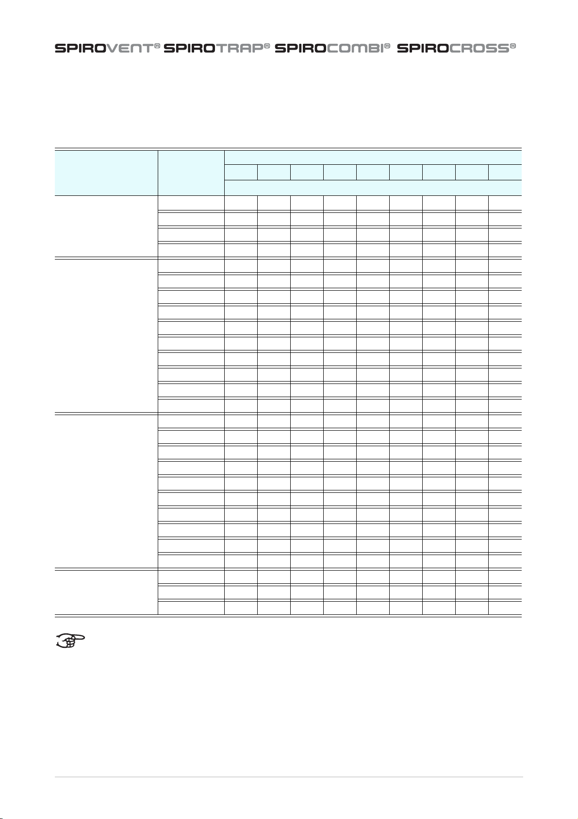
3.5 Torque values
3.5.1 All units
/i
3.5.2 Bolts for demountable bottom (for units
BD/HD and BF/HF)
/i
4SAFETY
4.1 Safety instructions
5 INSTALLATION AND
COMMISSIONING
5.1 Installation conditions
•Install the unit in a frost-free, well-ventilated place.
•Install the unit in accordance with the local
guidelines and rules.
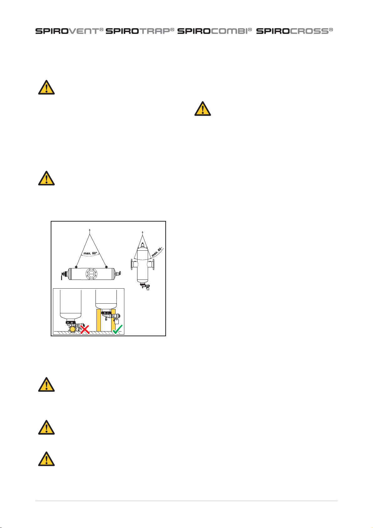
•Install the unit stress free and with the body in
vertical position.
•Do not use the unit as a support for pipework.
•It is not allowed to weld the unit to the pipework or
other external items unless the unit is specifically
designed to be welded into the pipework.
•It is not allowed to modify the unit.
•Apply the separately supplied product labels if the
labels on the product are not visible; for instance
after the unit has been insulated.
•Only for BE...M, BC...M, and XC...M: make sure that
there is enough space to replace the demountable
top/bottom or the dry pocket at the bottom (Xr).
Refer to section 3.4.
•The lifting lugs may only be used during the
installation.
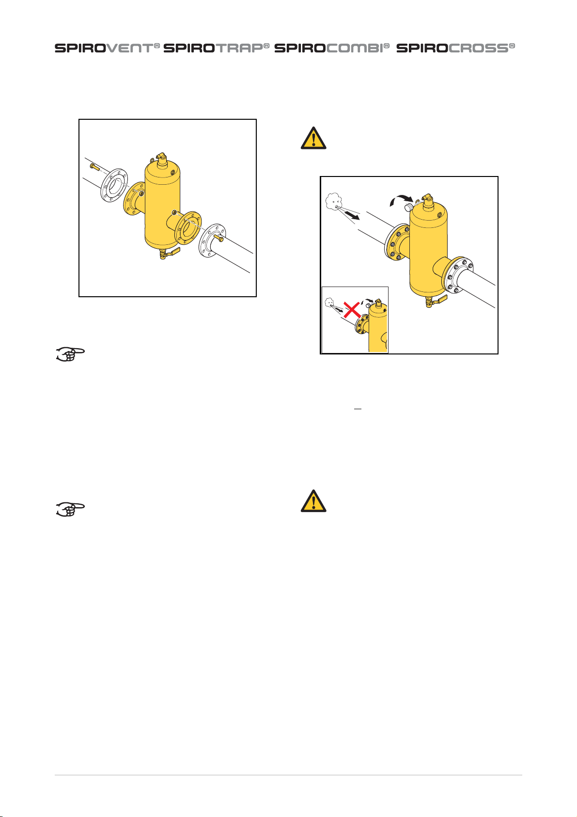
•The unit operates independent of the flow
direction.
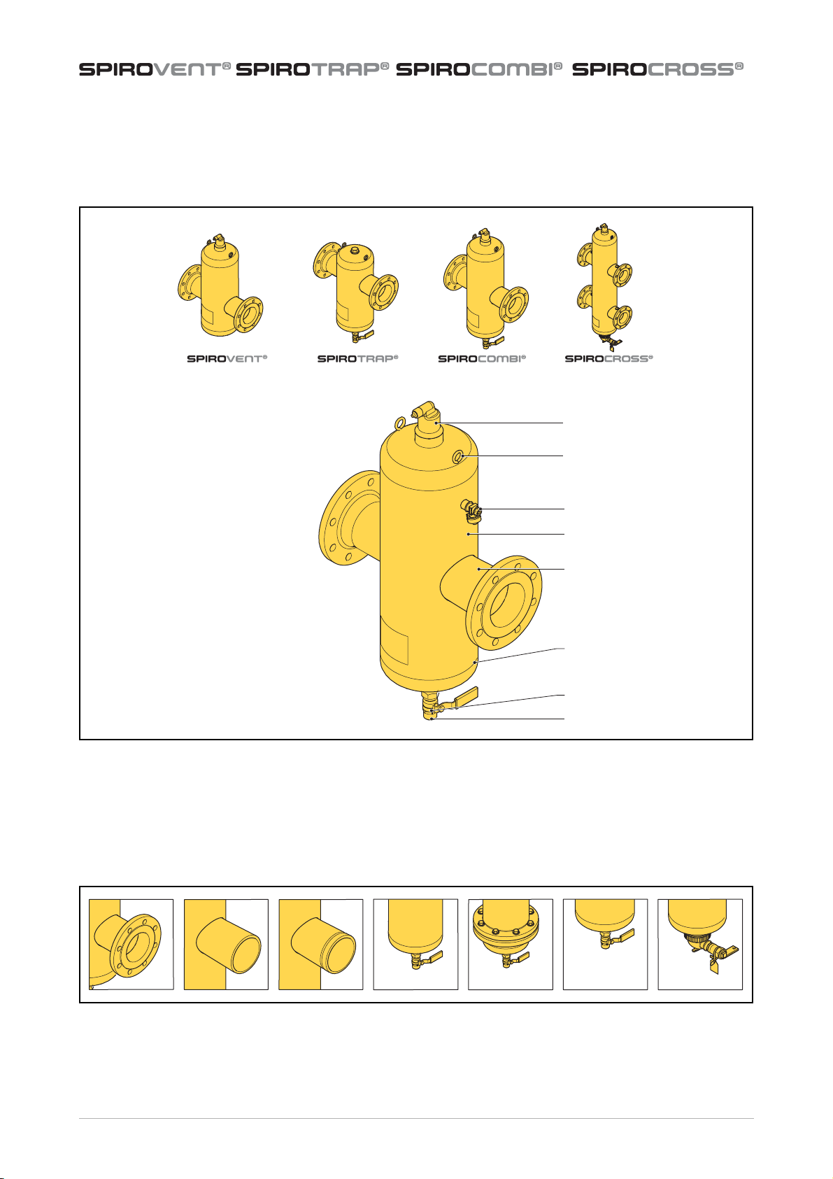
•Do not obstruct the automatic air vent (if available)
and make sure that the automatic air vent is always
easily accessible.
•A tube can be fitted to the air vent (1/2” female
thread on the outlet) to lead away the released
(smelly) air. Excessive dirt particles or foam forming
might cause a temporary leakage of the automatic
air vent.
•For SpiroCross XC...M: the unit (except DN50 and
DN65) has a sensor port (G½") at every branch.
These sensor ports are blinded. Sensors can be
mounted by removing the blind plug from the
ports. Make sure there is enough space for
mounting a sensor. The sensor can only be fitted
leak-proof with a thread sealant.
•If a drain pipe is fitted, make sure that this pipe is
fitted stress and vibration free to the drain valve.
Preferably, a flexible pipe or pipe parts should be
used (e.g. a hose).
•Do not obstruct the vent valve and keep all valves
accessible.
•The scum valve and the manual air valve are
designed to blow off and let in large quantities of
air during the filling and emptying of the
installation and to remove floating dirt.
•It is advisable to fit shut off valves at both sides of
the separator, especially for BD/HD, and BF/HF.
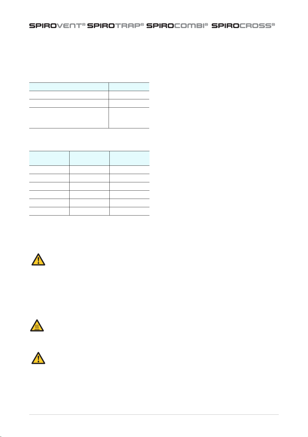
Item All types
Drain valve [Nm], min. - max. 40 - 80
Deaeration cap Handtight
Ring nut of the dry pocket [Nm],
min. - max. (only fo BE...M BC ...M
& XC...M)
15 - 40
Diameter [DN] Size To r q u e v a l u e
[Nm]
DN 050/065 M20 300
DN 080/100 M20 300
DN 125/150 M24 500
DN 200 M24 500
DN 250 M24 500
DN 300 M27 700
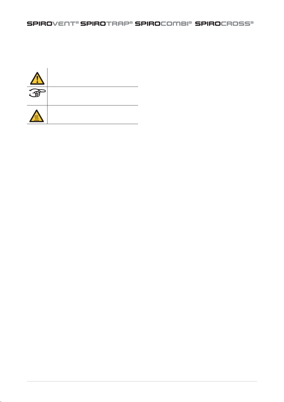
WARNING
•Installation and maintenance may only
be carried out by a qualified installer.
•When working on the unit, always
ensure there is no pressure in the unit,
let it cool down and remove the water
from the unit. This is not applicable
when draining dirt from the unit.
WARNING
Do not touch the unit or the pipework when
the system is in operation. The surfaces may
be hot and touching them may cause burns.
CAUTION
•Do not use the scum valve or drain valve
for (re)filling.
•Always install the unit body vertically,
with the automatic air vent (if available)
on top and the dry pocket or drain valve
(if available) at the bottom.