S+S Regeltechnik Rymaskon 200-Modbus Series User manual

Version: 10.10.2022 / TH
© S+S REGELTECHNIK GMBH | PIRANER STR. 20 | 90411 NÜRNBERG | GERMANY | FON +49(0)911 519470 | www.SplusS.de
Page 1 of 55
RYMASKON®200-Modbus
Modbus Slave User Manual
User Manual
for Room Control Units
RYMASKON®211-Modbus
RYMASKON®212-Modbus
RYMASKON®221-Modbus
RYMASKON®222-Modbus
RYMASKON®231-Modbus
RYMASKON®232-Modbus
RYMASKON®241-Modbus
RYMASKON®242-Modbus
RYMASKON®251-Modbus
RYMASKON®252-Modbus
RYMASKON®261-Modbus
RYMASKON®262-Modbus

RYMASKON®200-Modbus
Modbus Slave User Manual
© S+S REGELTECHNIK GMBH | THURN-UND-TAXIS-STR.22 | 90411 NÜRNBERG | GERMANY | FON +49(0)911 519470 |www.SplusS.de
Page 2 of 55
Abbreviations
ASCII American Standard Code for Information Interchange
IR Infrarot
LCD Liquid Crystal Display
NDEF NFC Data Exchange Format
NFC Near Field Communication
RGB Red, Green, Blue
URI Uniform Resource Identifier
URL Uniform Resource Locator
EU End User
SA System Administrator
DSEU Display Source for End User
DSSA Display Source for System Administrator
All Text and Data supplied within this manual are subjects to copyright protection.
Without the express written explicit approval of S+S Regeltechnik GmbH no part of this work may be copied or
distributed for any purpose, regardless in which way or by which means, electronically or mechanically.

RYMASKON®200-Modbus
Modbus Slave User Manual
© S+S REGELTECHNIK GMBH | THURN-UND-TAXIS-STR.22 | 90411 NÜRNBERG | GERMANY | FON +49(0)911 519470 |www.SplusS.de
Page 3 of 55
Table of Content
1. Introduction ................................................................................................................................................................4
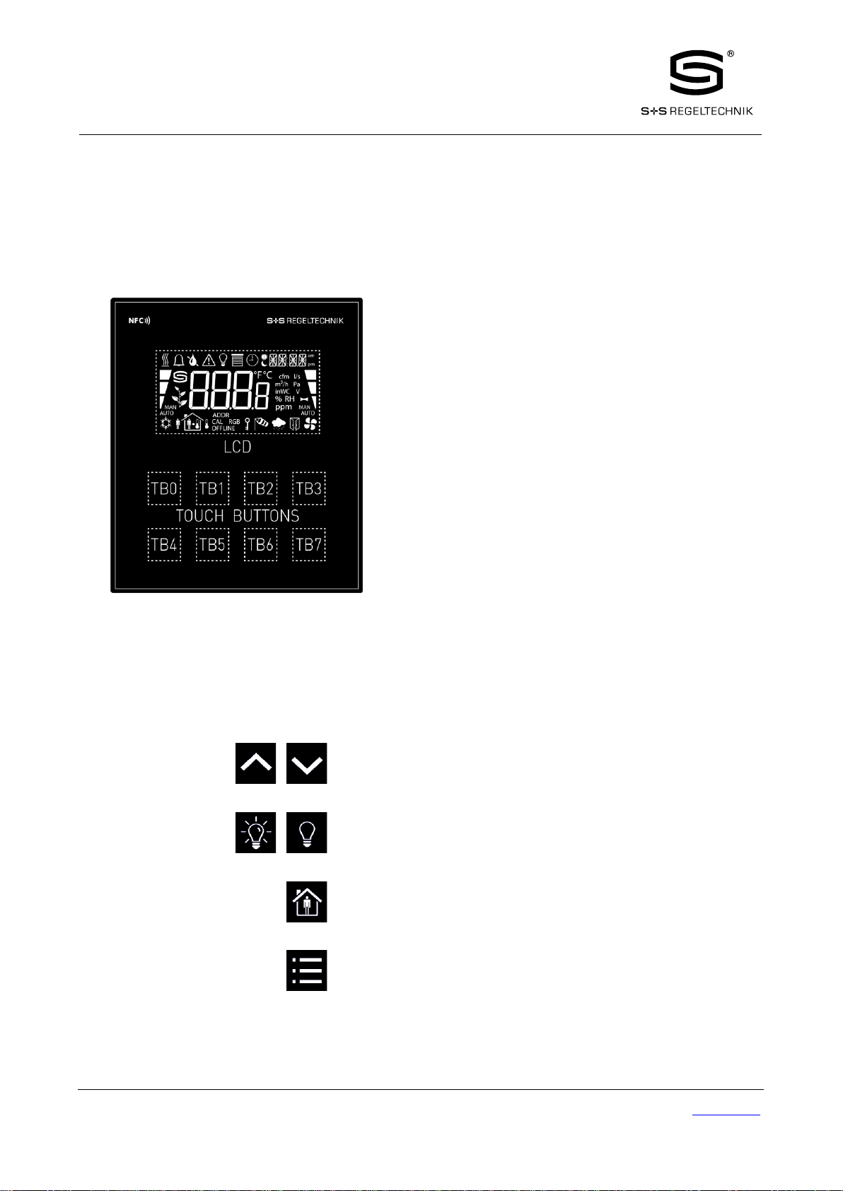
1.1. Overview..............................................................................................................4
1.2. Key Features........................................................................................................5
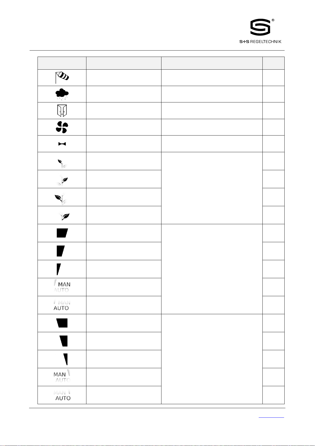
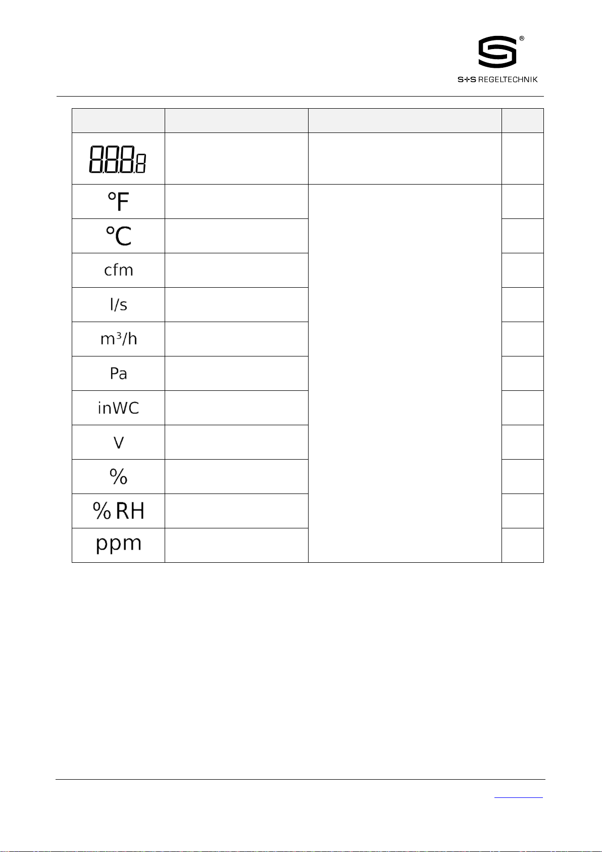
1.3. LCD Segments.....................................................................................................6
2. Quick-Start Guide.....................................................................................................................................................10
2.1. Hardware Installation.......................................................................................10
2.2. User Interface....................................................................................................11
2.2.1. General Description.................................................................................11
2.2.2 Operating Modes .....................................................................................12
2.2.3 Access Levels ..........................................................................................14
2.2.4 Device Settings ..........................................................................................15
2.2.5 Factory Default........................................................................................16
3. Modbus.....................................................................................................................................................................17
3.1. Introduction.......................................................................................................17
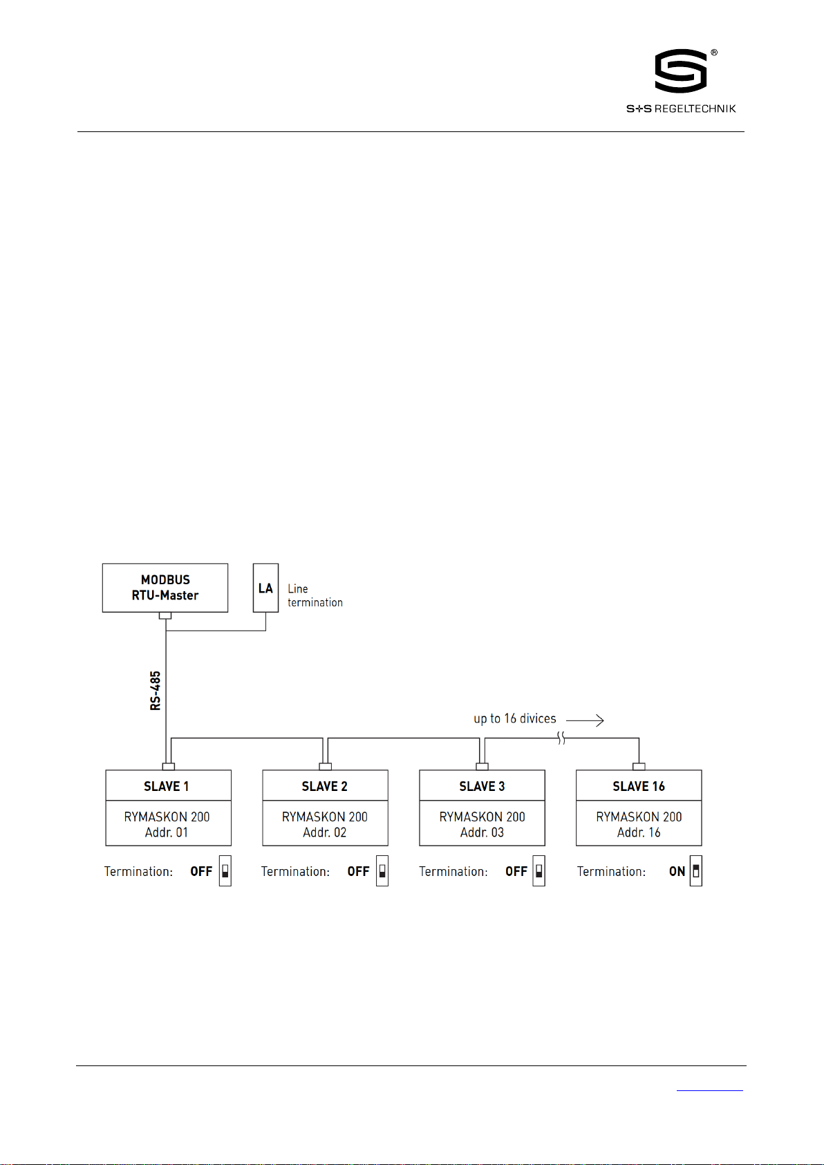
3.2. Modbus Network...............................................................................................17
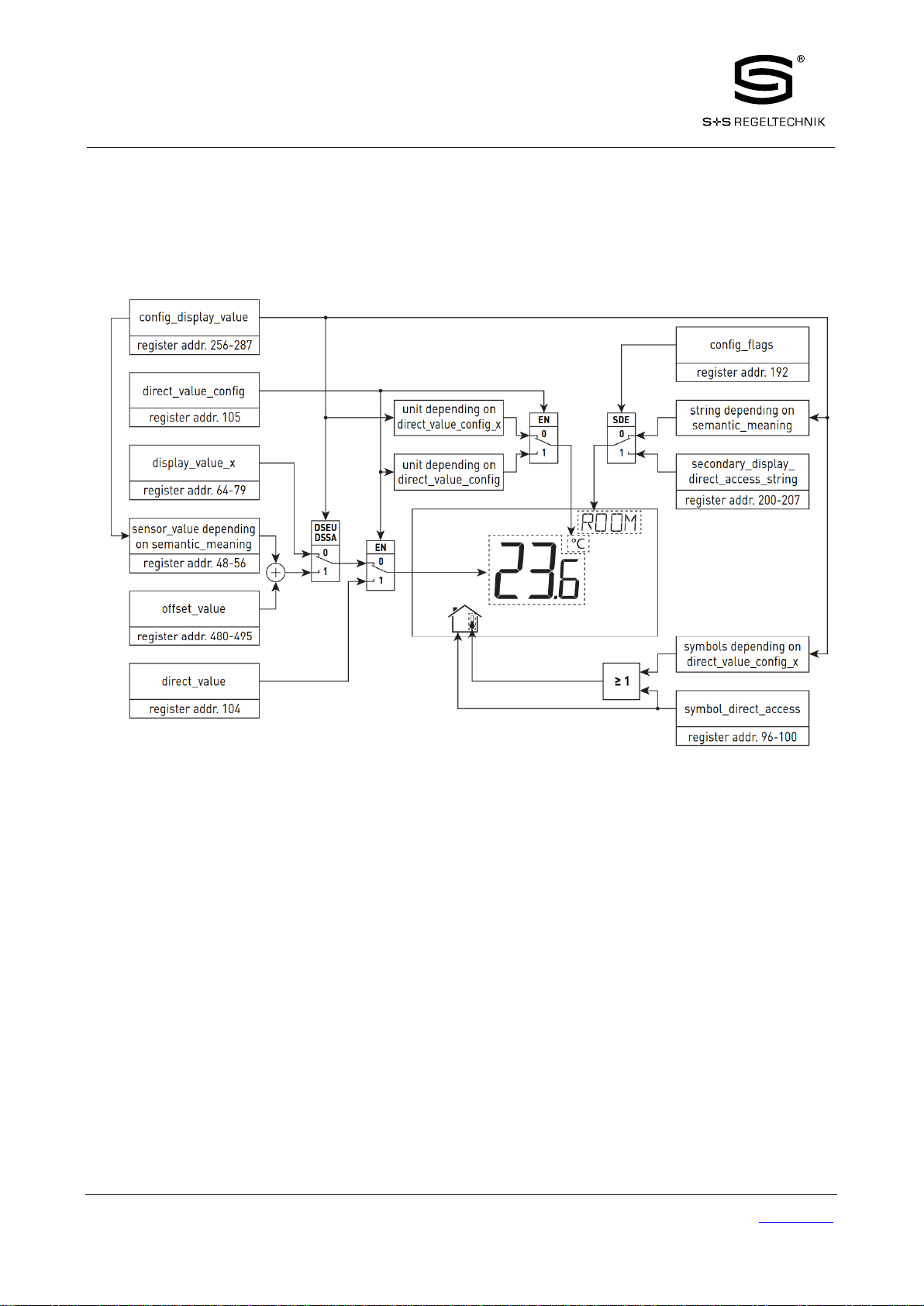
3.3. Modbus Register Usage for Value Display......................................................18
3.4. Modbusregister Description.............................................................................19
3.4.1 Data Registers..........................................................................................19
3.4.2 Device Settings........................................................................................27
3.4.3 Configuration Registers...........................................................................29
3.4.4 Model Information Registers (read only).................................................45
3.4.5 Device Information Registers (read only)................................................46
3.4.6 NFC Registers...........................................................................................47
3.4.7 Value Scaling and Stepwidth...................................................................49
4. NFC ..........................................................................................................................................................................50
5. IR-Remote Control Operation ..................................................................................................................................51
5.1. General Description..........................................................................................51
5.2. Remote Control Pairing....................................................................................52
6. Troubleshooting........................................................................................................................................................53
6.1. Technical Support.............................................................................................53
7. Specifications............................................................................................................................................................54
7.1. Physical Specifications......................................................................................54
7.2. Sensor Specifications.........................................................................................55

RYMASKON®200-Modbus
Modbus Slave User Manual
© S+S REGELTECHNIK GMBH | THURN-UND-TAXIS-STR.22 | 90411 NÜRNBERG | GERMANY | FON +49(0)911 519470 |www.SplusS.de
Page 4 of 55
1. Introduction
1.1. Overview
The RYMASKON 200 is a room control unit with a modern, minimalistic look that fits any interior design. It is
designed to be directly connected to a controller with a Modbus interface.
Up to 16 RYMASKON 200 devices can be connected to a single Modbus segment. RYMASKON 200 is equipped
with a segmented LCD display featuring an RGB backlight with adjustable color, offering a neat way to make the
RYMASKON 200 match the interior color concept of an office building. Eight capacitive touch buttons are used
to cycle through sensor values, display parameters, and adjust setpoints. Up to four external buttons can be
accessed and processed using Modbus interface.
The RYMASKON 200’s internal sensors measure temperature, humidity and dew point. Sensor values can be
displayed in SI or US units. Additionally, the date and time as well as the current level of eco-friendliness are also
displayed on the LCD display. Parameters controlled by the Modbus Masters’s logic can be overridden on the
RYMASKON 200, such as for occupancy, air conditioning, and ventilation. A direct access mode is available to
quickly adjust the most important setpoints e.g. for temperature and ventilation control.
A buzzer provides acoustic feedback for the touch buttons and can also be used to indicate alarms and error states.
To prevent unauthorized modifications, two access levels (end user, system integrator) are used, which are secured
via 4-digit pin codes. Device replacement and RYMASKON 200’s configuration are performed with very little
effort through the Modbus controller. The RYMASKON 200 is represented in the controller by a simple data point
interface, which can be directly connected to the IEC 61131 or IEC 61499 logic application and offers all common
functions for data points such as alarming, scheduling, trending, math functions, etc.
Using an NFC tag, the RYMASKON 200 transmits the URL to mobile devices. Last but not least, the
RYMASKON 200 comes with a built-in infrared receiver for comfortable remote control.

RYMASKON®200-Modbus
Modbus Slave User Manual
© S+S REGELTECHNIK GMBH | THURN-UND-TAXIS-STR.22 | 90411 NÜRNBERG | GERMANY | FON +49(0)911 519470 |www.SplusS.de
Page 5 of 55
1.2. Key Features
The different RYMASKON 200 models and their features are documented in Table 1.
CONTROL
Typ 210
Typ 220
Typ 230
Typ 240
Typ 250
Typ 260
Temperature up/down
Fan speed up/down
–
–
Light on/off
–
–
–
Sun protection up/down
–
–
–
Room occupancy
–
Menu
Table 1: Key Features
Not only the model type but also the enclosure color as well as the touch button layout is defined with the order
code. See Table 2 for possible order codes.
Nomenclature of Order Codes
Enclosure color:
xx1= black
xx2= white
Button layout:
21x
22x
23x
24x
25x
26x
Table 2: Possible Order Codes

RYMASKON®200-Modbus
Modbus Slave User Manual
© S+S REGELTECHNIK GMBH | THURN-UND-TAXIS-STR.22 | 90411 NÜRNBERG | GERMANY | FON +49(0)911 519470 |www.SplusS.de
Page 6 of 55
1.3. LCD Segments
The following Figure 1 shows the LCD of the device with all possible segments.
Figure 1: LCD Segments available on RYMASKON 200 displays
The following Table gives an overview of all available segments of the RYMASKON 200 with its defined names.
The Table also shows which symbols are directly accessible via Modbus registers (see Table 12 on Page 23).
Segment
Name
Deskription
Direct
Access
heat
Heating symbol
alarm_bell
Alarm bell symbol
drop
Drop symbol
drop_not
Cross out for drop symbol
alarm
Alarm symbol
light
Light bulb symbol
blinds
Sun blinds symbol
clock
Clock symbol

RYMASKON®200-Modbus
Modbus Slave User Manual
© S+S REGELTECHNIK GMBH | THURN-UND-TAXIS-STR.22 | 90411 NÜRNBERG | GERMANY | FON +49(0)911 519470 |www.SplusS.de
Page 7 of 55
Segment
Name
Deskription
Direct
Access
sun_left
Left half of sun symbol
sun_right
Right half of sun symbol
moon
Moon symbol
colon
The colon symbol of the secondary display
will only be available if the
secondary_display_direct_access_string
register at address 200 (see Table 22 Page
30) is not empty.
secondary_display
The secondary display is used to show time,
date and/or a short text depending on the
semantic meaning of a display value or set
point. It can also be directly accessed via the
Modbus register:
secondary_display_direct_access_string
(see Table 22 on Page 30).
am_pm_symbols
These symbols are not directly accessible but
are shown along with the time when 12h time
format has been selected.
-
cool
Cooling symbol
man_out
Man outside the house (no occupancy)
man_in
Man inside the house (occupancy)
arrow
Arrow symbol (to represent a set point)
temp_in
Temperature inside
temp_out
Tempareture outside
house
House symbol
text_symbols
The text symbols are not accessible via
Modbus but are shown at certain modes or
events.
-
key
The key symbol is primarily used to show that
a set point is pincode protected but it can also
be accessed via the symbol direct access
registers.

RYMASKON®200-Modbus
Modbus Slave User Manual
© S+S REGELTECHNIK GMBH | THURN-UND-TAXIS-STR.22 | 90411 NÜRNBERG | GERMANY | FON +49(0)911 519470 |www.SplusS.de
Page 8 of 55
Segment
Name
Deskription
Direct
Access
wind
Wind alarm symbol
rain
Rain alarm symbol
window
Window open alarm symbol
fan
Fan symbol
valve
Valve symbol
green_leaf_3
The green leaf symbols can be used to
display the level of eco-friendliness or
to visualize environmental conditions.
green_leaf_2
green_leaf_1
green_leaf_0
bar_left_2
The left bar graph symbols can be used to
display a heating or cooling stage in
automatic or manual mode.
bar_left_1
bar_left_0
manual_left
auto_left
bar_right_2
The right bar graph symbols can be used to
display a fan stage or valve position in
automatic or manual mode.
bar_right_1
bar_right_0
manual_right
auto_right

RYMASKON®200-Modbus
Modbus Slave User Manual
© S+S REGELTECHNIK GMBH | THURN-UND-TAXIS-STR.22 | 90411 NÜRNBERG | GERMANY | FON +49(0)911 519470 |www.SplusS.de
Page 9 of 55
Segment
Name
Deskription
Direct
Access
main_display
The main display is primarily used to show
certain values. It is not accessible directly.
-
unit_F
All unit symbols are not directly accessible
but are displayed along with a display value
or set point if the unit is set in the
corresponding configuration register.
See Table 27 on Page 35 for display value
configuration
and Table 28 on Page 37 for set point
configuration.
-
unit_C
-
unit_cfm
-
unit_l/s
-
unit_m³/h
-
unit_Pa
-
unit_inWC
-
unit_V
-
unit_%
-
unit_%RH
-
unit_ppm
-
Table 3: LCD Segments Overview

RYMASKON®200-Modbus
Modbus Slave User Manual
© S+S REGELTECHNIK GMBH | THURN-UND-TAXIS-STR.22 | 90411 NÜRNBERG | GERMANY | FON +49(0)911 519470 |www.SplusS.de
Page 10 of 55
2. Quick-Start Guide
2.1. Hardware Installation
Please refer to the RYMASKON 200 installation sheet for further information on dimensions, mounting and
wiring.
Figure 2 shows the back view of the device with the connection terminals for Modbus, 24 V DC-Supply and
external buttons. The four external buttons share a common GND connection which is internally connected to the
negative 24 V input terminal.
The external button terminal EB3 is also capable of sensing a NTC-10k temperature sensor. The temperature value
of the sensor will be provided on Modbus register address 49 (see Table 10 on Page 21). The cable length for
connecting the temperature sensor must not exceed 150m for 0.5mm² or 70m for 0.25mm² to guarantee a
temperature error less than 0.1% at 25°C.
Figure 2: Back View RYMASKON 200

RYMASKON®200-Modbus
Modbus Slave User Manual
© S+S REGELTECHNIK GMBH | THURN-UND-TAXIS-STR.22 | 90411 NÜRNBERG | GERMANY | FON +49(0)911 519470 |www.SplusS.de
Page 11 of 55
2.2. User Interface
2.2.1. General Description
The user interface consists of the LCD for displaying any desired value and up to eight touch buttons which are
used to adjust set points and change settings. Additionally up to four external push-buttons can be connected to the
device.
Figure 3: Front View RYMASKON 200
Each button can be configured individually via a Modbus register for its function (see Table 23 on Page 31). The
following listing gives you an overview which functionality can be associated with the buttons.
UP DOWN
change set point or device setting in EDIT-mode
directly access a set point in DISPLAY-mode
ON OFF
no specific function, the button state can be requested to control lighting
OCCUPANCY
no specific function, the button state can be requested to set occupancy
state
MENU
short press <3s: cycle through display values, set points or device
settings
long press ~3s: switch between DISPLAY-mode and EDIT-mode
long press >6s: switch to CLEANING-mode

RYMASKON®200-Modbus
Modbus Slave User Manual
© S+S REGELTECHNIK GMBH | THURN-UND-TAXIS-STR.22 | 90411 NÜRNBERG | GERMANY | FON +49(0)911 519470 |www.SplusS.de
Page 12 of 55
2.2.2 Operating Modes
In Figure 4 the operating modes of RYMASKON 200 are depicted. Each operating mode gives access to certain
Modbus registers that can either be viewed or edited depending on the mode. The following data is available:
•display values:
Are used to visualize data provided by the Modbus master or values
of internal sensors. It is viewed in DISPLAY-mode. For the display
value registers see Table 11 on Page 22 and Table 27 on Page 35 for
the corresponding display value configuration.
•set points:
Are used to visualize data that is provided by the Modbus master and
that can be edited by the user. It is shown in DISPLAY-mode and it
can be edited in EDIT-mode. For the set point registers see Table 31
on Page 41 and Table 28 on Page 37 for set point configuration.
The range in which a set point can be altered is defined by minimum
and maximum values that have to be written by the Modbus master.
Please refer to Table 32 on Page 42 and Table 33 on Page 43.
device settings:
These values define some basic settings of the device itself. Please
refer to Table 4 on Page 15 for a listing of all device settings and to
Table 18, Table 19 and Table 20 on Page 27 f. for the corresponding
Modbus registers. Device Settings can only be edited by the system
administrator in administration-mode.
•offset values:
Are used to add a certain offset to a display value. This functionality
can be used to calibrate sensor values. Offset values can be editet by
the system administrator in CALIBRATION-mode directly at the
device or over Modbus. Please see Table 34 on Page 44 for the offset
value register.
Figure 4: RYMASKON 200 Operating Modes

RYMASKON®200-Modbus
Modbus Slave User Manual
© S+S REGELTECHNIK GMBH | THURN-UND-TAXIS-STR.22 | 90411 NÜRNBERG | GERMANY | FON +49(0)911 519470 |www.SplusS.de
Page 13 of 55
When the device powers up, it enters DISPLAY-mode and it will display the first display value. When pressing
the MENU-button the next value will be shown. First all active display values and then all active set points are
displayed. After the last set point, the display will show the first display value again.
EDIT-mode is entered by pressing the MENU-button for more than 3 seconds. To enter the administration-mode
as system administrator two additionally defined buttons (TB0 and TB4) need to be pressed along with the
MENU-button for more than 3 seconds. Also in EDIT-Mode a short press on the MENU-button is used to go to
the next value. Any other button that has no specific function can be used in EDIT-mode to cycle the values in the
opposite direction. EDIT-mode is left when pressing the MENU-button for more than 3 seconds.
It is possible to edit the device settings in administration-mode.
CALIBRATION-mode will be entered for any display value when pressing one UP- and one DOWN-button
simultaneously for more than 3 seconds to adjust the offset. This mode is secured by the system administrator
password. CALIBRATION-mode is left when pressing the MENU-button for more than 3 second or after a
timeout of 1 minute.
An overview of all possible operating modes is given in Table 4 below. The operating mode can also be defined
by the Modbus master by writing the user interface direct access register (see Table 13 on page 23).
Table 4: Operating Modes
Order of Operating Modes
Description
0
DISPLAY-Mode / display values
Display values are shown.
1
DISPLAY-Mode / set points
Set points are shown.
2
EDIT-Mode / set points
Set points can be edited.
3
administration-Mode / device settings
Device settings can be edited. This mode is only accessible for
the system admi-nistrator.
4
CALIBRATION-Mode / offset values
Offset values can be edited
5
PINCODE-ENTRY / end user
The pincode for the end user has to be entered to show and/or
edit the requested value.
6
PINCODE-ENTRY / system administrator
The pincode for the system administator has to be entered to
show and/or edit the requested value.
7
DIRECT_ACCESS-Mode / set points
A defined set point can be accessed and edited without entering
EDIT-mode. It can be entered by pressing a defined button (see
Table 23 on page 31). In contrast to EDIT-mode only
predefined set points can be edited.
The DIRECT_ACCESS-mode can be left by pressing any
button that has no direct access capability.
10
CLEANING-Mode
This mode is used to clean the surface of the device without
any response of the touch buttons and hence any unwanted
changes. This mode is entered by pressing the MENU-button
for at least 6 seconds. After 10 seconds with no interaction the
device will switch back to DISPLAY-mode automatically.

RYMASKON®200-Modbus
Modbus Slave User Manual
© S+S REGELTECHNIK GMBH | THURN-UND-TAXIS-STR.22 | 90411 NÜRNBERG | GERMANY | FON +49(0)911 519470 |www.SplusS.de
Page 14 of 55
2.2.3 Access Levels
There are two access levels (end user & system administrator) with configurable rights to display and edit values.
Each access level is secured by a four digit pincode that will be requested if EDIT-mode or
DIRECT_ACCESS-mode is entered and the desired value is pincode protected.
Per default the pincode for end user and system administrator access level is disabled (0000). Otherwise the
pincode can be entered as described in Figure 5.
Figure 5: Pincode Entry

RYMASKON®200-Modbus
Modbus Slave User Manual
© S+S REGELTECHNIK GMBH | THURN-UND-TAXIS-STR.22 | 90411 NÜRNBERG | GERMANY | FON +49(0)911 519470 |www.SplusS.de
Page 15 of 55
2.2.4 Device Settings
The following Table gives an overview of the device settings accessible through the button interface as well as via
Modbus. For the corresponding Modbus registers please refer to Table 18, Table 19 and Table 20 on Page 27 and
following.
Parameter
Value
Default
Your
Setting
Modbus Parity
Odd / Even / None
None
Modbus Baudrate
1.2kB / 2.4kB / 4.8kB / 9.6kB / 19.2kB /
38.4kB / 57.6kB / 115.2kB
57,6kB
Modbus Address
1 - 247
1
Pincode System Administrator
0000 –9999
(if 0000 the pincode is disabled)
0000
Pincode End User
0000 –9999
(if 0000 the pincode is disabled)
0000
Color Setting LCD Backlight Red
0% - 100%
100%
Color Setting LCD Backlight Green
0% - 100%
100%
Color Setting LCD Backlight Blue
0% - 100%
100%
Brightness LCD Backlight
0% - 100%
100%
LCD Contrast
0% - 100%
100%
LCD Color Scheme
0 –user (as defined above)
1 –white
2 –red
3 –green
4 –blue
5 –orange
6 –magenta
7 –cyan
0
Time Format
24h / 12h
24h
Show Date
on / off
off
Show Time
on / off
off
Acoustic Feedback (for Touch Buttons)
on / off
on
Goto First Display Value (the first
display value will be displayed after 1
minute without inter-action)
on / off
on
Display Auto Shuffle
on / off
off
Display Auto Dim
(lcd brightness will be dimmed after 2
minutes with no interaction)
off / 50% / 10% / 0%
off
Unit System
SI / US
SI
Device Restart
off –if a DOWN-button is pressed the
device will be rebooted manually
-
Table 5: Device settings

RYMASKON®200-Modbus
Modbus Slave User Manual
© S+S REGELTECHNIK GMBH | THURN-UND-TAXIS-STR.22 | 90411 NÜRNBERG | GERMANY | FON +49(0)911 519470 |www.SplusS.de
Page 16 of 55
2.2.5 Factory Default
The factory default configuration for display values and set points depends on the specific RYMASKON 200
model. The following Table shows the factory default values for each model. See Table 27 on page 35 for display
value configuration and Table 28 on Page 37 for set point configuration.
Register Name
Inhalt
display_value_0
Internal Temperature
display_value_1
Relative Humidity
display_value_2
Dew Point
display_value_3
-
display_value_4
Supply Voltage
display_value_5
External Temperature
display_value_6 to display_value_15
-
set_point_0
Internal Temperature Set Point
set_point_1
Fan Stage
set_point_2 to set_point_15
-
Table 6: Factory Default for RYMASKON 200

RYMASKON®200-Modbus
Modbus Slave User Manual
© S+S REGELTECHNIK GMBH | THURN-UND-TAXIS-STR.22 | 90411 NÜRNBERG | GERMANY | FON +49(0)911 519470 |www.SplusS.de
Page 17 of 55
3. Modbus
3.1. Introduction
The device operates as a Modbus slave in Modbus RTU mode. The default baudrate is set to 57600, the default
parity is set to ‘none’ and the default address is set to 1. The communication with a Modbus master device will
work with Modbus function code 0x03 (Read Holding Registers) and Modbus function code 0x06 (Preset Single
Register). Section 3.4 shows all available Modbus registers.
3.2. Modbus Network
Figure 6 illustrates a typical Modbus network setup with a linear bus topology used to connect several slave
devices to a master device. The transmission line has to be terminated at both ends. At the master device this can
be done by connecting a termination resistor.
Each RYMASKON 200 is equipped with a built-in 120Ω termination resistor. Set the termination switch to OFF
except on the last device on the bus where the termination switch must be turned ON. Per default each device has
the Modbus address set to 1. Because each address can only be used once it has to be configured at the device
settings in administration-mode.
For further information please see Section 2.2.
Figure 6: Modbus Network

RYMASKON®200-Modbus
Modbus Slave User Manual
© S+S REGELTECHNIK GMBH | THURN-UND-TAXIS-STR.22 | 90411 NÜRNBERG | GERMANY | FON +49(0)911 519470 |www.SplusS.de
Page 18 of 55
3.3. Modbus Register Usage for Value Display
The following Figure 7 shows, which Modbus registers have influence on a displayed value, unit, text on the
secondary display or symbols.
Depending on settings in configuration registers different combinations are possible to achieve the desired result.
Figure 7: Modbus Register Usage for Value Display

RYMASKON®200-Modbus
Modbus Slave User Manual
© S+S REGELTECHNIK GMBH | THURN-UND-TAXIS-STR.22 | 90411 NÜRNBERG | GERMANY | FON +49(0)911 519470 |www.SplusS.de
Page 19 of 55
3.4. Modbusregister Description
In the following sections the RYMASKON 200 Modbusregister.
Modbus registers are described. Abbrevations are explained at the end of each table. ‘R’ indicates that this value is
not used by now and that it is reserved for future use. Square brackets ‘[]’ indicate that this is the initial value.
Numbers with the prefix ‘0x’ are hexadecimal values. Values with no prefix indicate decimal values.
3.4.1 Data Registers
These registers contain data that is changing frequently. This data is not stored persistent in the device and will be
lost after a reboot.
Register Name
Register
Address
Bit Position
15
14
13
12
11
10
9
8
7
6
5
4
3
2
1
0
present_state
0
0x0000
R
[0]
R
[0]
R
[0]
R
[0]]
EB3 [0]
EB2 [0]
EB1 [0]
EB0 [0]
TB7 [0]
TB6 [0]
TB5 [0]
TB4 [0]
TB3 [0]
TB2 [0]
TB1 [0]
TB0 [0]
short_pressed
1
0x0001
IRC
[0]
NFC
[0]
R
[0]
R
[0]
long_pressed
2
0x0002
R
[0]
ERR
[0]
DOC
[0]
SPC
[0]
The present_state register always represents the actual state of the buttons.
The short_pressed and long_pressed states will remain set until the flags are cleared by the Modbus
master by writing a logical ‘1’ to the specific flag The long_pressed state of a button will remain set as
long as the button is pressed.
Bits 0-11 indicate the states of the buttons (TBx-touch button, EBx-external button)
NFC:
NFC flag, is set if an NFC field was detected. This gives the information that a user is reading
the NFC tag memory with an NFC enabled mobile device. For more information see Chapter 4.
IRC:
infrared remote control flag, is set when an infrared remote control code was received. The
received code can be read via the ir_remote_control_command register at register address 32
(see Table 9 on page 20).
SPC:
Set point changed flag, is set when a set point was changed.
Each set point has an individual change flag at register address 3 (see Table 8 on page 20).
DOC:
device setting or offset value changed flag, is set when a device setting or offset value was
changed. he specific change flags can be read via the registers at address 4 and 5 (see Table 8
on page 20).
ERR:
error flag, is set when an internal error has occurred.
!!! Button states and flags can have the following binary values:
1 –pressed, set
0 –released, cleared
!!! The present_state register is only updated in DISPLAY- and DIRECT_ACCESS-mode!
(For a list of possible modes see Table 4 on page 13)
Table 7: Button States and Flags

RYMASKON®200-Modbus
Modbus Slave User Manual
© S+S REGELTECHNIK GMBH | THURN-UND-TAXIS-STR.22 | 90411 NÜRNBERG | GERMANY | FON +49(0)911 519470 |www.SplusS.de
Page 20 of 55
Register Name
Register
Address
Bit Position
15
14
13
12
11
10
9
8
7
6
5
4
3
2
1
0
change_flags_
set_points
3
0x0003
SP15
[0]
SP14
[0]
SP13
[0]
SP12
[0]
SP11
[0]
SP10
[0]
SP9
[0]
SP8
[0]
SP7
[0]
SP6
[0]
SP5
[0]
SP4
[0]
SP3
[0]
SP2
[0]
SP1
[0]
SP0
[0]
change_flags_
device_settings
4
0x0004
R
[0]
R
[0]
R
[0]
R
[0]
R
[0]
R
[0]
R
[0]
DS8
[0]
DS7
[0]
DS6
[0]
DS5
[0]
DS4
[0]
DS3
[0]
DS2
[0]
DS1
[0]
DS0
[0]
change_flags_
offset_values
5
0x0005
OV15
[0]
OV14
[0]
OV13
[0]
OV12
[0]
OV11
[0]
OV10
[0]
OV9
[0]
OV8
[0]
OV7
[0]
OV6
[0]
OV5
[0]
OV4
[0]
OV3
[0]
OV2
[0]
OV1
[0]
OV0
[0]
The change flag register states will remain true until the flags are cleared by the Modbus master by
writing a logical ‘1’ to the specific flag.
!!! Change flags can have the following binary values:
1 –true / 0 –false
!!! If a set point, device setting or offset value is changed by the user the corresponding flag will be set
and it has to be cleared by the Modbus master.
SP0 to SP15:
change flags for set_point_0 to set_point_15 (see Table 31 on page 41)
DS0:
change flag for modbus_parameter on register address 176 (see Table 18
on page 27)
DS1:
change flag for pincode_system_administrator on register address 177 (see Table
19 on page 27)
DS2:
change flag for pincode_end_user on register address 178 (see Table 19
on page 27)
DS3:
change flag for lcd_color_red on register address 179 (see Table 20 on page 28)
DS4:
change flag for lcd_color_green on register address 180 (see Table 20 on page 28)
DS5:
change flag for lcd_color_blue on register address 181 (see Table 20 on page 28)
DS6:
change flag for lcd_brightness_contrast on register address 182 (see Table 20
on page 28)
DS7:
change flag for user_interface_settings on register address 183 (see Table 20
on page 28)
DS8:
change flag for display_unit on register address 192 (see Table 21 on page 29)
OV0 to OV15:
change flags for offset_value_0 to offset_value_15 (see Table 34 on page 44)
Table 8: Change Flags
Register Name
Register
Adresse
Bit Position
15
14
13
12
11
10
9
8
7
6
5
4
3
2
1
0
ir_remote_control_
command
32
0x0020
button_code
[0x00]
remote_id
[0x00]
This register provides the button_code and remote_id of a valid command received via the infrared
receiver. See Chapter 5 for detailed information.
!!! Whenever a command was received the ir_remote_control_command register is updated and the IRC
flag of the short_pressed register at address 1 is set (see Table 7 on Page 19).
Table 9: IR Remote Control Command
Other manuals for Rymaskon 200-Modbus Series
1
This manual suits for next models
12
Table of contents
Other S+S Regeltechnik Control Unit manuals

S+S Regeltechnik
S+S Regeltechnik THERMASREG FM Series Repair manual

S+S Regeltechnik
S+S Regeltechnik RYMASKON 400-Modbus User manual

S+S Regeltechnik
S+S Regeltechnik Rymaskon 600 User manual

S+S Regeltechnik
S+S Regeltechnik Rymakson 400-Modbus Repair manual

S+S Regeltechnik
S+S Regeltechnik Rymaskon 200-Modbus Series User manual

S+S Regeltechnik
S+S Regeltechnik RYMASKON 700 Series User manual