manuals.online logo
Brands
  1. Home
  2. •
  3. Brands
  4. •
  5. NuAire
  6. •
  7. Control Unit
  8. •
  9. NuAire CT-A Instruction Manual

NuAire CT-A Instruction Manual

CONTENTS Page
Maintenance
Introduction.
Installing the control unit.
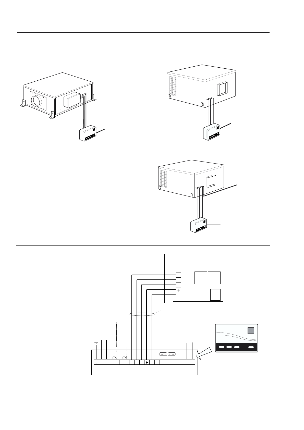
Applications and wiring diagrams
Operating the twinfan mains control.
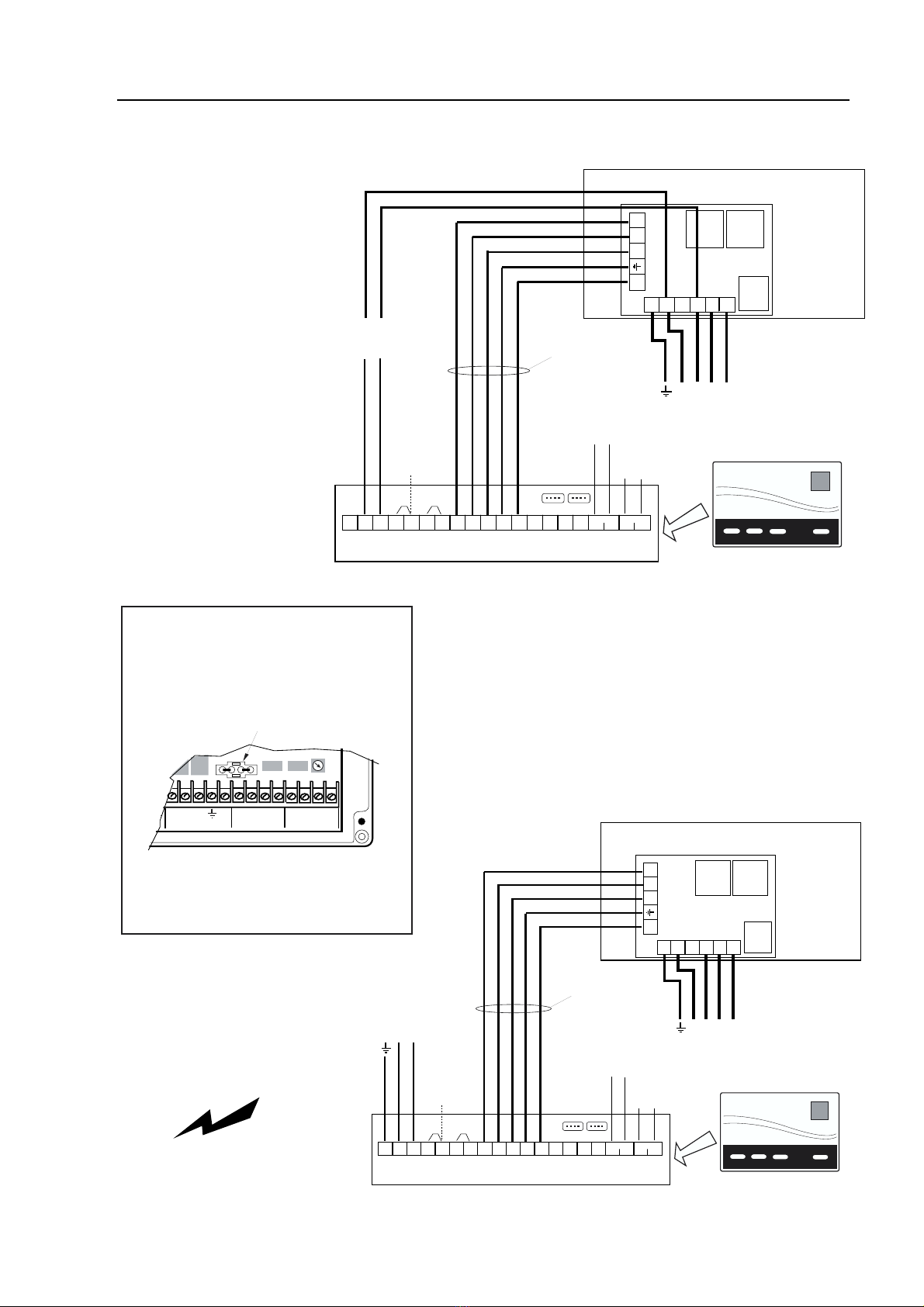
Terminal connections
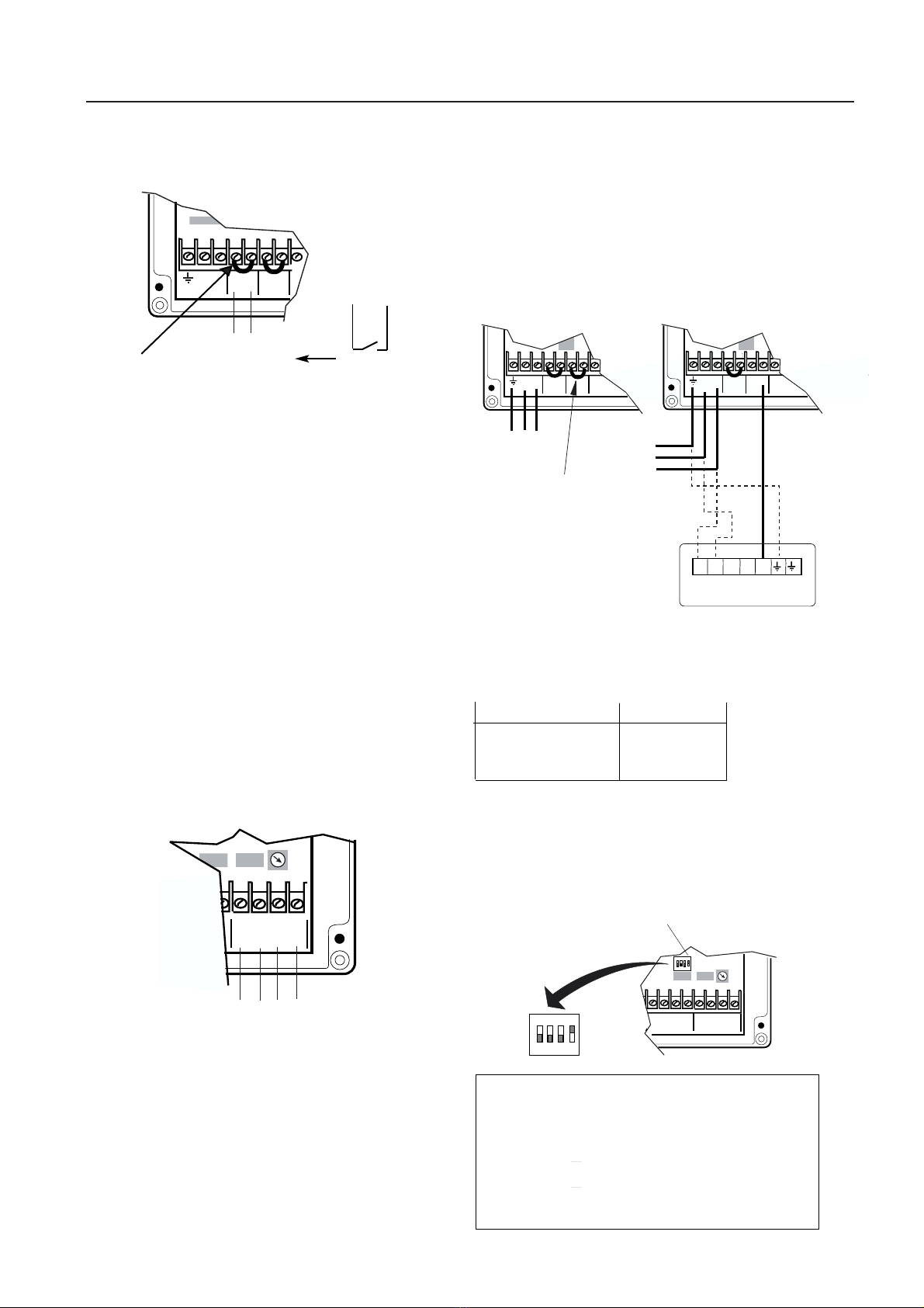
Run on Timer adjustment.
Switched Live connections.
Remote Run / Remote Fail connections.
Connecting a Speed Control.
Resetting Function switches.
Certification
Installation
and Maintenance
Mains ‘C’
Twin Fan Control
CT-A (auto duty share)
CT-M (manual duty share)
NuAire Limited
Western Industrial EstateCaerphilly,
CF83 1XH United Kingdom
Telephone 029- 20 88 5911
Facsimile No. 029 2088 7033
Email: info @ nuaire. co.uk
www.nuaire.co.uk
Leaflet No. 670912
JULY 2001
1
Maintenance
The control requires no maintenance other than cleaning.
Disconnect supply and clean with a damp cloth. Do not spray
any cleaning fluids onto the control
Introduction
This control has been designed specifically to suit NuAire
Quietwin Twinfan Extract units.
Two versions of the control are available.
1) Manual Duty Sharing (CT-M model).
2) Automatic Duty Sharing (CT-A model).
Both models provide automatic change over from a failed fan to
the standby fan. A list of unit features is shown opposite.
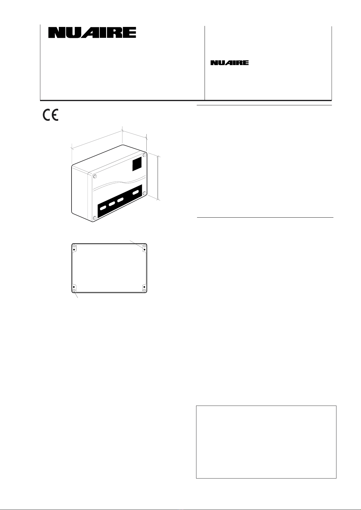
A general view of the unit with overall dimensions is shown in
fig. 1.
Installing the control unit
Carefully remove the case cover (4 screws). Drill the main case
to allow the necessary cable access.
NOTE:
It is the responsibility of the installer to ‘seal’ the cable
entries and to maintain the IP rating of the unit.
Select a suitable surface mounting position and fix the main cas-
ing to it using the four case mounting holes provided. (fig 2).
ISOLATE THE ELECTRICAL SUPPLY and make your
main electrical supply and fan unit connections to the terminals
inside as shown in fig. 8.
FEATURES
IP 65 (Protection).
Remote Fail (volt free contacts).
Remote Run (volt free contacts).
Switched Live operation.
Adjustable run on 0-60 min.
Audible failure indication.
Visual failure indication.
Auto Duty Share (CT-A only. 12 hr intervals).
Microsave compatible.
Automatic Changeover on failure.
Failure detection of fan by Hall Effect sensors.
IMPORTANT
The installation must be carried out by qualified personnel in
accordance with the appropriate authority and conforming to all
statutory and governing regulations eg. IEE, CIBSE, COHSE etc
.
.
.
.
.
.
.
.
.
.
.
Case mounting holes
Cover fixings
Figure 1. Unit overall dimensions (mm)
Figure 2. Fixing holes
1
1
1
2
4
4
4
5
5
5
5
6
Controls Application Service (CAS)
A team of Engineers and technicians is available to provide
pre and post order support.
We are on hand to provide help and advice from the most
basic use of any NuAire equipment to the more complex
applications, maximising on the versatility of our control
products.
Telephone: 029 2085 8585
Facsimile: 029 2085 8586
The EMC directive: 89/336/EEC
with modification 92/31/EEC
The low voltage directive 73/23/EEC
200 80
150
Installation and Maintenance TWINFAN CONTROL
2
Single Phase application
400V 3 phase
Mains Supply
to Fan
Mains controller
Four core & earth
230V cable connection
required to control
230V 1 phase
Mains Supply
to Control
Single Phase 230V
Mains Supply into
Control
4 core & earth
230V cable connection
to fan
Twinfan
control
NuAire QTI Twinfans
Control Applications
NuAire QTE & QTR Twinfans
BELT DRIVE
Mains controller
Four core & earth
230v cable connection
required to fan.
Single Phase
230V Mains supply
to Control
Single Phase application.
Three Phase application.
N L L SL L FL L1
L2 N H
BL RD BK Y RUN FAULT
Connection
for speed
control
(Link must be
removed when
using a speed
control)
1 phase fans
only
L1 L2 N H
QUIETWIN FAN Single phase
230v MAINS CONTROL
230V 1 phase
supply
NOTE:
supply to fan is via the control
Link Link
NET
CT-AVI
- Audible / Visual
Indicator
connection
230V
Switched Live
Connection
(twinfan operates
when live, remove
link when used)
Volt Free
Contacts
Rated 230V 5A
(for run indication
if required)
Volt Free
Contacts
Rated 230V 5A
(for fail indication
if required)
4 core
& Earth
Cable
CONNECTION BOX IN FAN
Single Phase
Quietwin units
wiring diagram
Figure 3.
Control Applications
Figure 4.
3
Installation and Maintenance TWINFAN CONTROL
Three Phase Fans
(1ph power for
control unit
taken from Fan).
E N L R Y B
N L1 L2 L3
3ph 400V 50Hz supply
E N L L SL L FL L1
L2 N E H
BL RD BK Y RUN FAULT
230V MAINS CONTROL
Link Link
NET
CT-AVI
- Audible / Visual
Indicator
connection
QUIETWIN FAN Three phase
230V
Switched Live
Connection
(twinfan operates
when live, remove
link when used)
Volt Free Contacts
Rated 230V 5A
(for run indication
if required)
Volt Free Contacts
Rated 230V 5A
(for fail indication
if required)
L1 L2 N H
CONNECTION
BOX IN FAN
4 core
& Earth
Cable
230V power to control
from fan only requires
N & L to be connected
to N & R
E N L R Y B
N L1 L2 L3
400V 3 ph 50Hz supply
E N L L SL L FL L1
L2 N E H
BL RD BK Y RUN FAULT
230V MAINS CONTROL
Link Link
NET
CT-AVI
- Audible / Visual
Indicator
connection
QUIETWIN FAN Three phase
230V
Switched Live
Connection
(twinfan operates
when live, remove
link when used)
Volt Free Contacts
Rated 230V 5A
(for run indication
if required)
Volt Free Contacts
Rated 230V 5A
(for fail indication
if required)
L1 L2 N H
CONNECTION BOX IN FAN
4 core
& Earth
Cable
230V 1ph 50Hz supply
Three Phase fan units
(1ph power for control
taken from independent
source)
Note:
Installation must comply with
electrical regulations as detailed
on page 1
Figure 5.
Figure 6.
Details of alternative supply
wiring to Mains Control
IMPORTANT NOTE:
(BELT DRIVE TWINFANS)
A link plug is factory fitted to match this
Twinfan Control to single phase twinfans
When using the Twinfan Control with a
belt drive twinfan you must first remove
this link plug which is located on
the circuit board.
L FL L1 L2 N H BL RD BK Y RUN FAULT
FAN FAN UNIT ICP RR RF
LIVE
Remove this plug to allow
control of belt drive fans
Installation and Maintenance TWINFAN CONTROL
4
Operating the Twinfan Mains Control
Pressing any of the panel buttons will be accompanied by an
audible confirmation tone. The button functions are listed below.
Duty Share
(This button appears on CT-A models only).
Pressing this button will enable or disable the duty sharing feature.
When the Duty Share light is on, duty sharing is selected.
Fail
There are two ‘FAIL’ indicators, one under each Fan button. The
fail indicators show which fan has failed. In the event of a failure,
an audible alarm will also sound for 15 seconds. If the internal
configuration switches have been selected for a continuous audible
alarm, the alarm will continue until the fault is rectified.
Power
Pressing this button switches the unit ON or OFF. When
switched ON the associated light will show GREEN. When the
unit is switched OFF the light will show RED.
An AMBER light will indicate the unit is switched ON but there
is no 230v signal connected to the SL terminal inside the case.
WARNING
Switching the unit OFF on the front panel Power button
does not isolate the fan or the control.
Figure 7.
Twinfan Control buttons
Power
Fail Fail
Duty
Share
Fan 2Fan 1
Explanation of the button functions.
Fan 1 / Fan 2
Pressing either button selects that fan to run. If there is a fan
failure, the fail indicator will remain illuminated even after the fail-
ure has been rectified and the control must be reset (by pressing
the fan button to restart the fan.
Connections
to fan
Supply
230V ac. 50Hz
N L L SL L FL L1 L2 N H BL RD BK Y RUN FAULT
SUPPLY SWITCHED FAN FAN UNIT ICP RR RF
LIVE LIVE
Main terminal connections
Figure 8.
Connections to Control.
Run on Timer adjustment
A Run On facility is provided so that when the 230V ac signal
is disconnected from the SL terminals the fans can continue to
run on for a period of up to 60 minutes. The run on time is
set using a rotating screw (See fig. 9).
When the 230V ac signal is disconnected, the power lamp on
the front of the unit will illuminate AMBER to indicate there
is no SL signal.
Figure 9.
Run on adjustment
BL RD BK Y RUN FAULT
ICP RR RF
Run On
rotary
adjustment
0-60 mins
(clockwise)
Installation and Maintenance TWINFAN CONTROL
5
Switched Live connections
Typical Uses: PIR. / Light Switch. / BMS.
A control signal must be routed from the 230V line via the PIR or
light switch to the SL terminal on the unit and the factory link
between the terminals L / SL must be removed. (See figure
10). When 230V ac. is sensed on these terminals, the control will
be actuated.
NOTE:
If you do not require SL switching you should retain the
factory fitted link between terminals L & SL and set the run
on timer to 0 minutes.
N L L SL L FL L1
SUPPLY SWITCHED FAN
LIVE LIVE
230V ac 50Hz
control signal
connection
Remove
this link
Figure 10.
Connections for Switched Live.
Internal user selectable function switches
A configuration switch block is provided so that the installer can
enable or disable certain functions. The small switch block is
located just above the ‘NET’ sockets near the run on timer
adjuster (see figure 13)
Configuration
Switches
N L L SL L FL L1 L2 N H BL RD BK Y RUN FAULT
FAN UNIT ICP RR RF
LIVE LIVE
1 2 3 4
ON
1 2 3 4
ON
Switch Switch Switch
number position function
ON / OFF
1Do not reset this particular switch (retain as set by factory)
2OFF Disables audible alarm
3OFF Unit will not switch off.
4Do not reset this particular switch (retain as set by factory)
Figure 13.
Function switches
L SL
P.I.R. sensor
or Light Switch
BL RD BK Y RUN FAULT
ICP RR RF
(A) (B) (C) (D)
A volt free relay is included to provide status if any fan is running
(Maximum load is 5amp 230V ac.) When a fan is running, A&B
are connected. When a fan has failed, C&D are connected.
Figure 11.
Remote Run & Remote Fail connections
Remote Run and Remote Fail connections
Using a Speed Control with a Quietwin
(SINGLE PHASE TWINFANS ONLY)
When using a Single Phase Twinfan it is possible to connect a
Speed Control to modify the output of the fan when commission-
ing the system. Details of suitable Speed Controls are shown
below.
When using a speed control with a single phase Twinfan, the
factory link between terminals L and FL must be removed.
The output of the Speed control should then be connected to the
FL terminal (See figure 12).
Remove
factory link
between
L & FL
230V 1ph
50Hz
Supply
N L L SL L FL L1 L2 N H BL RD BK Y RUN FAULT
SUPPLY SWITCHED FAN FAN UNIT ICP RR RF
LIVE LIVE
N L L SL L FL L1 L2 N H BL RD BK
SUPPLY SWITCHED FAN FAN UNIT ICP
LIVE LIVE
Regulated output
from speed control
to FL terminal
230V 1ph
50Hz
Supply
L N L2 N L1
ESC1 Speed Control
Figure 12.
Using a speed control
(1 phase only).
Fan Unit Code Speed Control
QTI, QTE, QTR 1 - 5 ESC1-3A
QTI, QTE, QTR 6 ESC1-6A
QTI, QTE, QTR 7 - 8 ESC1-10A
Speed Control
selection
Technical or commercial considerations may,
from time to time, make it necessary to alter the
design, performance and dimensions of
equipment and the right is reserved to make
such changes without prior notice.
Western Industrial Estate,
Caerphilly, Mid Glam CF83 1XH
United Kingdom.
Telephone: 029 2088 5911
Facsimile: 029 2088 7033,
Email: [email protected]
www.nuaire.co.uk
Leaflet No. 670912
GP168
Installation and Maintenance TWINFAN CONTROL
5

This manual suits for next models

1

Other NuAire Control Unit manuals

NuAire XBOXER XBC Series Assembly instructions

NuAire

NuAire XBOXER XBC Series Assembly instructions

NuAire ES-LCD Manual

NuAire

NuAire ES-LCD Manual

NuAire ES-UCF User manual

NuAire

NuAire ES-UCF User manual

NuAire NSC1-A-B Series User manual

NuAire

NuAire NSC1-A-B Series User manual

NuAire Basicmaster User manual

NuAire

NuAire Basicmaster User manual

NuAire MRXBOXAB-ECO5-AECV User manual

NuAire

NuAire MRXBOXAB-ECO5-AECV User manual

NuAire IAQ-V125 User manual

NuAire

NuAire IAQ-V125 User manual

NuAire CM-XBOX-INLINE User manual

NuAire

NuAire CM-XBOX-INLINE User manual

Popular Control Unit manuals by other brands

Edwards LCPV16EKA instruction manual

Edwards

Edwards LCPV16EKA instruction manual

Cooper Crouse-Hinds eLLK 92 NIB Series Supplementary instructions

Cooper Crouse-Hinds

Cooper Crouse-Hinds eLLK 92 NIB Series Supplementary instructions

Grant GEO360 Installation & user's instructions

Grant

Grant GEO360 Installation & user's instructions

Bray KUGELHAHN MULLER KM20 Installation, operation and maintenance manual

Bray

Bray KUGELHAHN MULLER KM20 Installation, operation and maintenance manual

HYDAC International C4WERE 6 instruction manual

HYDAC International

HYDAC International C4WERE 6 instruction manual

CALEFFI SATK40 Series INSTRUCTIONS FOR INSTALLATION, COMMISSIONING AND MAINTENANCE

CALEFFI

CALEFFI SATK40 Series INSTRUCTIONS FOR INSTALLATION, COMMISSIONING AND MAINTENANCE

EOS EmoToych II AF Assembly instruction

EOS

EOS EmoToych II AF Assembly instruction

Arduino MKR1000 Getting started

Arduino

Arduino MKR1000 Getting started

Union Switch & Signal GENISYS II Hardware installation

Union Switch & Signal

Union Switch & Signal GENISYS II Hardware installation

National Instruments 9225 CALIBRATION PROCEDURE

National Instruments

National Instruments 9225 CALIBRATION PROCEDURE

Lawler 802 Installation & maintenance manual

Lawler

Lawler 802 Installation & maintenance manual

esera automation Shutter Pro V4 user guide

esera automation

esera automation Shutter Pro V4 user guide

Monacor PA-1200IRD Installation and operating instructions

Monacor

Monacor PA-1200IRD Installation and operating instructions

ARI-Armaturen STEVI 350 Series Operating and installation instructions

ARI-Armaturen

ARI-Armaturen STEVI 350 Series Operating and installation instructions

Nexcom NEIO-B1812 Quick reference guide

Nexcom

Nexcom NEIO-B1812 Quick reference guide

Klark Teknik QFLEX ISOLATOR quick start guide

Klark Teknik

Klark Teknik QFLEX ISOLATOR quick start guide

United Electronic Industries DNx-AO-308-353 user manual

United Electronic Industries

United Electronic Industries DNx-AO-308-353 user manual

Bose ControlSpace CC-64 Safety instructions & install guide

Bose

Bose ControlSpace CC-64 Safety instructions & install guide

manuals.online logo
manuals.online logoBrands
  • About & Mission
  • Contact us
  • Privacy Policy
  • Terms and Conditions

Copyright 2025 Manuals.Online. All Rights Reserved.