Sport-thieme 114 5713 User manual

1110704 · © 2019 Sport-Thieme GmbH
Assembly Manual
Sport-Thieme®
Swimming Line Trolleys
Art.-Nr. 114 5713
114 5739
Art.-Nr. 114 5713
Art.-Nr. 114 57039
D-38367 Grasleben ·Germany
sport-thieme.com · info @sport-thieme.com
Phone: +49 53 57 181 543 · Fax: +49 53 57 181 921

2
Assembly Manual for Art.-Nr. 114 5713/5739
1. Scope of delivery:
Please check the following content before assembly.
Total content:
2 frame side parts
2 round reel side parts
1 reel tube
1 hoop
2 crossbars
1 accessories
Accessories:
6 hexagon socket countersunk head screws M8 x 16mm, DIN 7991
12 hexagon socket screws M8 x 16mm, DIN 933
2 hexagon socket screws M8 x 85mm, DIN 931
4 hexagon socket screws M8 x 80mm, DIN 931
2 threaded eyes V2A, M8 x 20mm
2 nuts M8, DIN 934
18 self-locking nuts M8, DIN 985
2 washers Ø outside 28mm, hole Ø 15.5mm, DIN 125-1, V2A
2 washers Ø outside 44mm, hole Ø 26mm, DIN 126 M24, galvanized
2 plastic caps Ø 40mm
2 plates, 40 x 20mm, black
2 plastic cas 50x30mm, black
2 polyamide liners 40 x 40 mm, length 35 mm
2 screwing devices
1 wing screw M8 x 16mm
1 VA composing stick, round 9mm
1 grooved pin V2A, DIN 1473, 3 x 20mm
2 plug plates with thread M8
2 rubber wheels, grey
2 sockets for wheel
1 assembly instruction
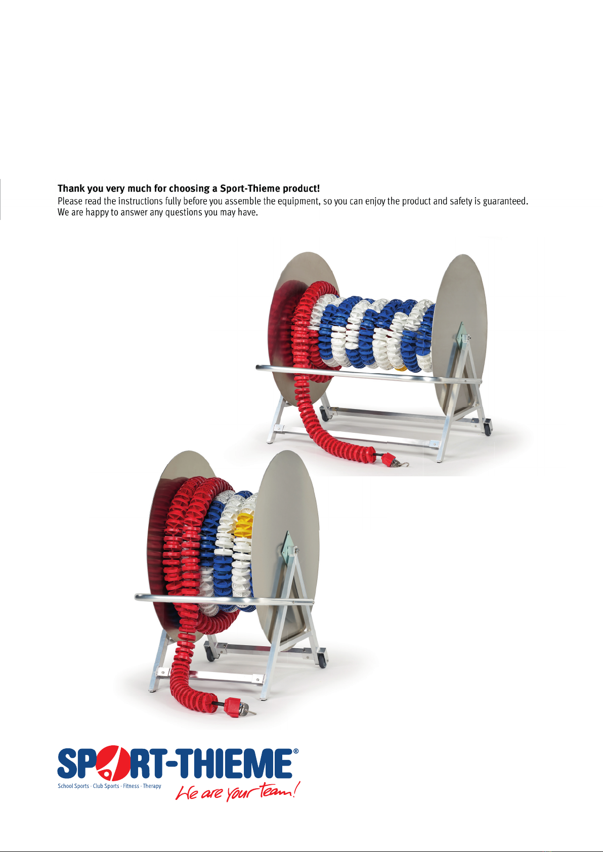
2. Preparation for assembly:
We recommend the assembly on a suitable surface to avoid damages of the proles!
Preparation: Open crate and unpack all parts.
The following tools are necessary:
- gloves (to protect against possible cuts to prole edges)
- 2 combination wrenches 13 mm
- 1 hammer/mallet
- 1 drill Ø 9.5mm

3
Assembly Manual for Art.-Nr. 114 5713/5739
3. Assembly of wheels and caps at frame side parts:
At rst stick sockets through wheel hubs.
Lay both frame side parts on the ground and stick wheels into side parts. Push from the outside hexagon socket screws DIN 931,
M8 x 85mm through holes of frame and sockets. Then screw from the inside self-locking nuts M8, DIN 985 and tighten screws.
Close open ends of the frame with plastic caps 50 x 30mm. Use a hammer/mallet if necessary.
Fix plastic plates 40x20mm in bottom holes of frame side parts. Use a hammer/mallet if necessary.

4
Assembly Manual for Art.-Nr. 114 5713/5739
4. Assembly of crossbars at frame side parts:
Lay side part on the ground. Stick 2 crossbars (U-prole) into the sleeves welded at the side part (U-prole). Push from the out-
side 3 hexagon socket screws M8 x 16mm, DIN 933 through holes of U-proles of each crossbar and screw slightly from the
inside 2 self-locking nuts M8, DIN 985.
Then stick 2nd side part on crossbars. Screw again 3 hexagon socket screws M8 x 16mm, DIN 933 and 2 self-locking nuts M8,
DIN 985 through holes of U-proles as mentioned above. Now place and adjust already mounted frame on rollers/feet. At rst
tighten screws at U-proles so that crossbars t closely at sleeves. Afterwards tighten all other screws.
5. Assembly of reel:
(for the assembly 2 persons are necessary)
At rst screw 2 nuts M8, DIN 934 on 2 threaded eyes M8x25mm.
Place reel tube on a suitable construction (supports, table
or similar, height approx. 600 mm).

5
Assembly Manual for Art.-Nr. 114 5713/5739
Connect reel tube, side parts and plates as follows:
- Set side part against the flange of reel tube
- Hold plug plate at side part
- Adjust all parts and holes
To x the plug plate stick threaded eye from the reel
tube side through the flat hole of reel tube flange and
side part (see left picture) and screw it slightly into the
plate.
Attention: The reel tube has to be protected against slipping and
overturning before the following assembly!
Screw from the reel tube side 3 countersunk head screws M 8x16mm, DIN 7991 through
countersunk holes of the reel tube flange and side part into the plug plate and tighten
them.
Screw threaded eye so far that it doesn’t stick out of
the plates outside. Then x nut M8.
Now repeat the above mentioned assembly steps on the other side of the reel tube.
Current state of assembly:

6
Assembly Manual for Art.-Nr. 114 5713/5739
7. Assembly of reel at side part:
Stick 1 washer Ø outside 44 mm, DIN 126 and then
1 polyamide liner 40 x 40 mm on the plugs.
To insert the reel press both side parts outwards and push
polyamide liners into the square attachments. One side part
is equipped with a welded sleeve to lock the reel later.
Stick 1 washer Ø outside 28mm, DIN 125-1 on the provided
screwing device and screw it rmly into the thread of the
plug plate. Make sure that the reel can move freely.
Current state of assembly:

7
Assembly Manual for Art.-Nr. 114 5713/5739
7. Assembly of handlebar:
Adjust holes of handlebar and side parts.
Note: Take care that the handlebar is
mounted opposite to the rollers.
Stick from the outside of each side part 2 hexagon socket screws M6 x 80mm, DIN 933
through holes of handlebar and side parts and x them with 2 self-locking nuts M6, DIN
Use a hammer/mallet to x plastic caps Ø 40 mm in both sides of the handlebars.

8
Assembly Manual for Art.-Nr. 114 5713/5739
8. Assembly of reel lock:
For safety reasons during transport and to avoid unrolling of lane markers the trolley is equipped with a reel lock.
A sleeve with thread M8 is welded on one of the reel
supports. Bore a hole for the lock through the sleeve with
drill Ø 9.5 mm at any position in the round side part.
Push from the outside composing stick Ø 9mm through the
sleeve hole and x it with a wing bolt M8 x 16.
Use a hammer or mallet to x the grooved pin 3 x 20mm
in the hole of the composed stick so that it projects equally
at both sides.
To lock the reel unlock wing bolt, push composing stick
into the hole at the round side part and then tighten wing
bolt.

9
Assembly Manual for Art.-Nr. 114 5713/5739
9. Maintenance, storage and safety instructions:
Check screws regularly and change damaged and wearing parts if need be.
Take care that during use the trolley is located on a horizontal surface and the guide roller is locked.
Permanent contact with water may cause damages of aluminium parts and other material components.
Additives in the water of swimming pools can intensify these eects.
Therefore we recommend to clean the trolley with clear water after each use and to dry it with a soft cloth.
Only use water to clean surfaces and no alcohol or aggressive substances!
Note: Due to our continuous quality check of products and equipment technical modications are possible.
This manual suits for next models
1
Table of contents